Background
This is a limited-scope technical examination report, based on ATSB examination and analysis using evidence provided to the ATSB by external parties. The ATSB did not attend the accident site or conduct other activities normally associated with an ATSB occurrence investigation. The information contained in this technical examination report is released in accordance with section 25 of the Transport Safety Investigation Act 2003.
The occurrence
On 12 August 2023, an amateur-built gyroplane, registered G‑2468, collided with terrain while conducting circuit training near Allworth, New South Wales. The instructor pilot was fatally injured and the student pilot was seriously injured.
The Australian Sport Rotorcraft Association (ASRA) produced an investigation report into the occurrence which was obtained by the ATSB to assist with this technical examination. The investigation report made a number of observations and findings including that:
- The gyroplane had descended inverted, almost vertically through trees.
- Other than pieces of the propeller blades, the entire wreckage was located within a 5-metre radius.
- The tail unit fitted to the gyroplane was second hand and had previously been repaired due to accident damage.
- The rudder post (shaft) was not original and had failed in-flight.
The report concluded that ‘the rudder post failed inflight which initiated sequential failures that resulted in the complete detachment of the majority of the tail unit from the gyroplane’ which rendered the gyroplane uncontrollable.
Purpose of the examination
As part of an investigation by the Coroner’s Court of New South Wales, the New South Wales Police Force requested assistance from the ATSB in the examination of components from the gyroplane’s tailplane. The ATSB conducted an examination and assessment of the fractured rudder shaft and fibreglass structure including previous repairs.
Sources of information
The ATSB was supplied with and examined the following components:
- The fibreglass sections of the tailplane that had fractured into several pieces and separated from the keel during the accident sequence
- The upper half of the fractured rudder shaft and attachment hardware retained within the base of the rudder.
The ATSB was provided with or obtained the following additional information:
- ASRA accident report, which included extracts from the aircraft’s logbook
- relevant Magni Gyro design drawings and maintenance documentation.
Context
Tailplane history
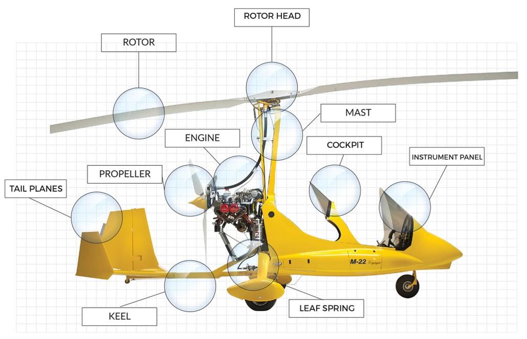
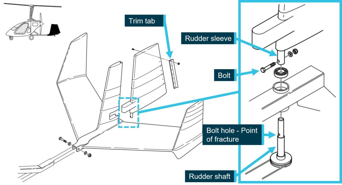
Gyroplane G‑2468 was fitted with a tail assembly from a factory-built Magni Gyro M22. In the factory installation, the tail assembly was mounted on an aluminium box section in line with the rest of the keel (Figure 1). The rudder mechanism employed a pulley below the keel that turned a rudder shaft, which passed through the box section and was then bolted longitudinally to a tube fixed within the rudder (Figure 2).
Figure 1: Magni Gyro M22
Source: Magni Gyro
Figure 2: Magni Gyro tail assembly
Source: Magni Gyro, modified by the ATSB
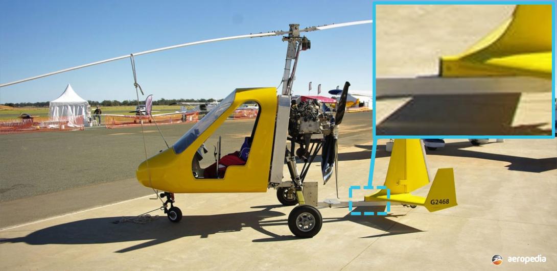
In contrast, when installed to G‑2468, the tailplane was welded to the top of the existing keel, which introduced a second aluminium box section into the structure (Figure 3). The additional box section meant that the original rudder shaft was not long enough for this installation, and a replacement was manufactured.
Figure 3: Tail installation on G-2468, highlighting the modified double-height keel
Source: Aeropedia, modified by the ATSB
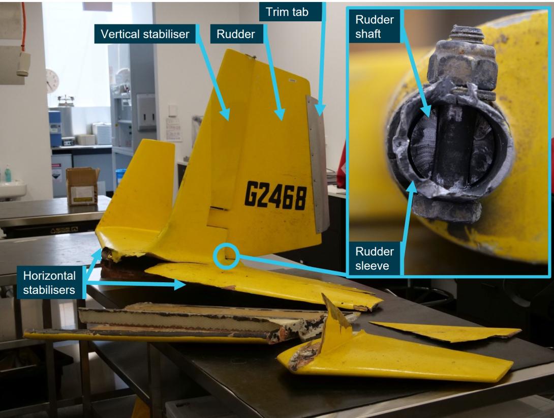
The parts supplied for examination are shown in Figure 4. In addition to the requested examination, the ATSB noted that the trim tab on the trailing edge of the rudder was not original and had a larger surface area. Magni Gyro was unable to comment on the influence on flight loads of the rudder trim tab modification.
Figure 4: G‑2468 tailplane as supplied for examination
Source: ATSB
The gyroplane’s logbook indicated it was manufactured in 2009 and had accrued approximately 510 flight hours at the time of the accident. The tail was reported to have undergone fibreglass repairs twice due to rollover accidents; once in 2008 (prior to the manufacture of G-2468) and again in February 2015 at 243 flight hours. The logbook recorded that a new rudder shaft was ‘manufactured and installed’ as part of those repairs. Since that time, the fibreglass structure was repaired twice for observed cracking, at 250 flight hours (November 2016) and 401 flight hours (August 2020).
Tailplane examination
Rudder assembly
The rudder shaft was fractured at the point coincident with the bolt hole for attachment to the outer rudder sleeve (Figure 2, 4). The fracture surface exhibited extensive ‘beach mark’ features consistent with high cycle fatigue[1] crack progression (Figure 5). ATSB examination using optical and scanning electron microscopy identified that cracks had originated at all 4 corners of the bolt hole and progressed across approximately 98% of the cross-sectional area before final fracture.
Figure 5: Rudder shaft fatigue fracture surfaces, and bolt hole exhibiting fretting wear
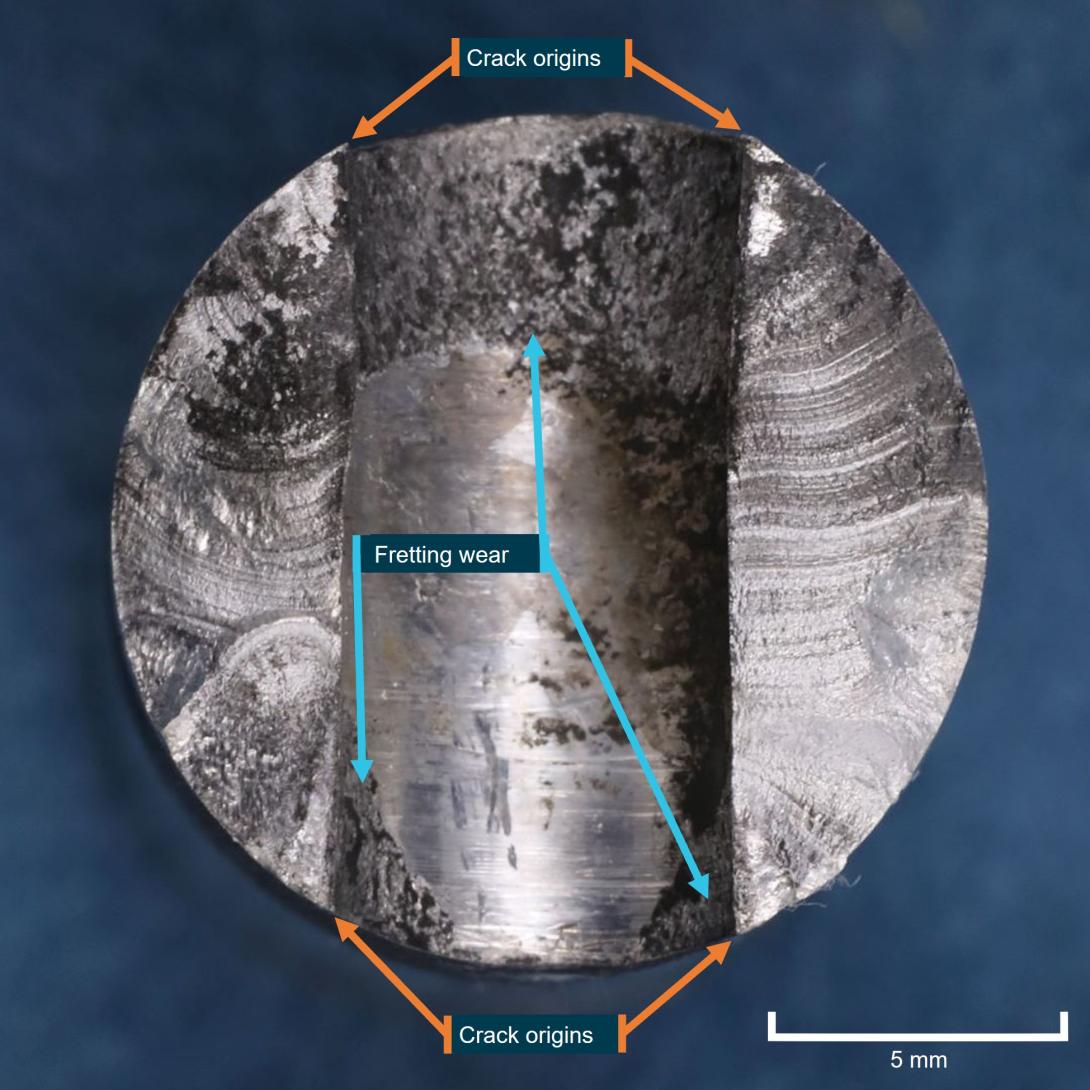
Note: Concentric beach marks radiating outwards from the corners of the central bolt hole. The inside edges of the bolt hole are not square, and there is a difference in cross sectional area between the two sides of the fracture; The bolt hole is slightly offset to the left of the shaft centreline.
Source: ATSB
There was evidence of severe fretting[2] wear between the bolt and the shaft bolt hole. The shaft bolt hole was enlarged at either end, likely due to material loss from the fretting wear. The hole was slightly offset from the shaft centreline and there were no fillets applied to the hole edges for stress relief.
There was also wear between the shaft and the rudder outer sleeve (Figure 6), and between the outer sleeve and the bolt (Figure 7). The sleeve bolt holes were deformed (‘ovalised’) and one side was fatigue-cracked.
Compared to the original design in Figure 1, the rudder sleeve had been shortened and the bolt hole had been changed from the original longitudinal (fore-aft) orientation to a lateral (left-right) orientation. The original M5 (nominal 5 mm diameter) rudder attachment bolt (Figure 2) had been replaced with a 6.25 mm (1/4 inch) bolt, meaning the bolt hole in the rudder shaft and sleeve were similarly oversized. It was not possible to measure the assembly torque on the nut, due to the shaft fracture, deformation and wear.
Energy dispersive x-ray analysis (EDS) of the fractured rudder shaft showed that it was likely manufactured from a 6xxx-series aluminium rod.[3] The shaft diameter measured 14.85 mm across the unworn area adjacent to the bolt hole. Drawings supplied by Magni Gyro showed that the original rudder shaft was a nominal 15 mm diameter,[4] 2.5 mm thick tube, manufactured from SAE 4130N[5] steel.
Figure 6: Rudder shaft wear from contact with outer sleeve
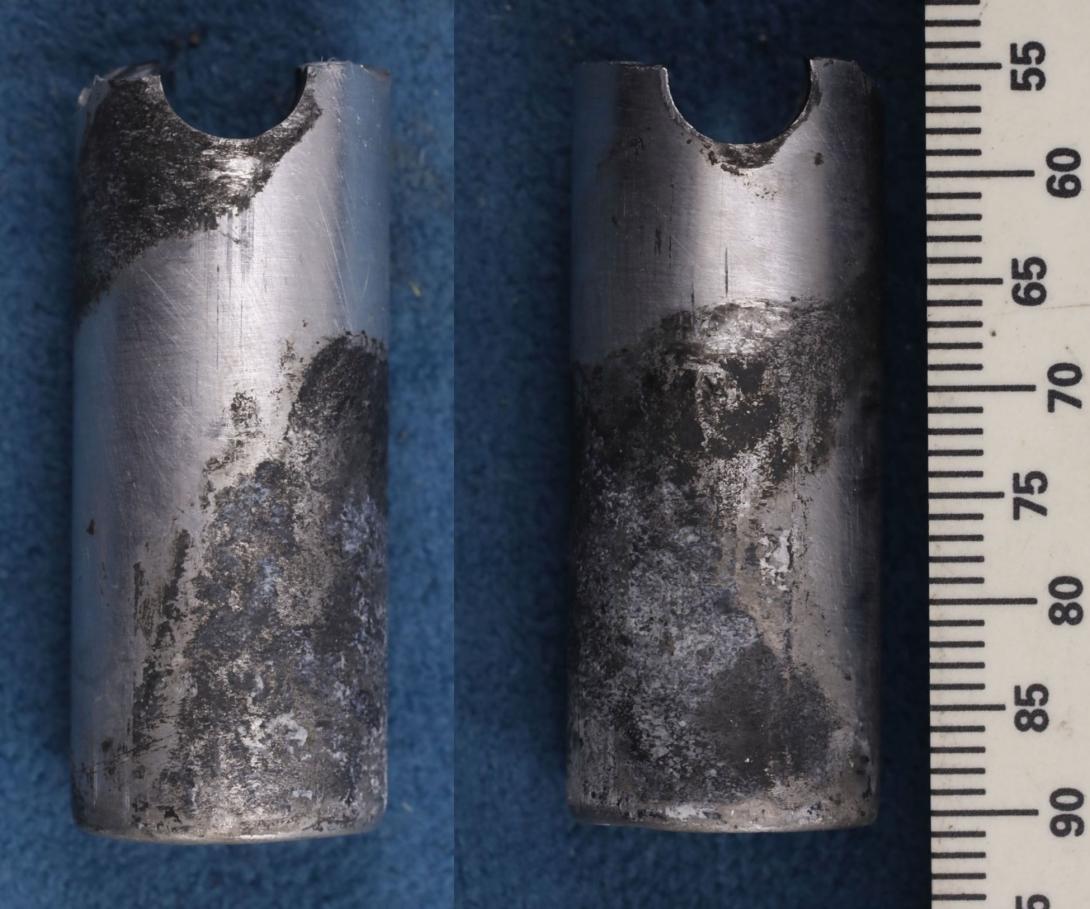
Scale in millimetres.
Source: ATSB
Figure 7: Rudder sleeve wear from contact with washer, and associated cracking
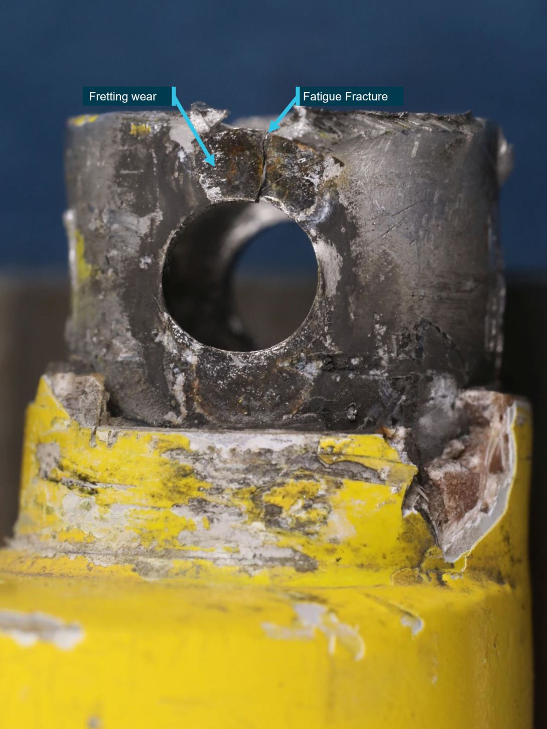
Source: ATSB
Tail structure
As shown in Figure 4, the majority of damage to the fibreglass tail structure was to the left side. The vertical tip was separated, the lower skin and spar was split from the left horizontal stabiliser and a triangular-shaped piece had fractured from the upper skin. No sections had separated from the right side of the tail, however there were large splits in the upper and lower skins at the leading and trailing edges. The underside of the right horizontal stabiliser, adjacent to the keel, appeared to have been sanded in preparation for painting, however the paint coating had not been applied.
There were 2 areas of paint and fibreglass damage to the leading edge of the left stabiliser upper skin (Figure 8). There was also a cut through the upper skin and a larger puncture spanning both halves of the upper skin sections.
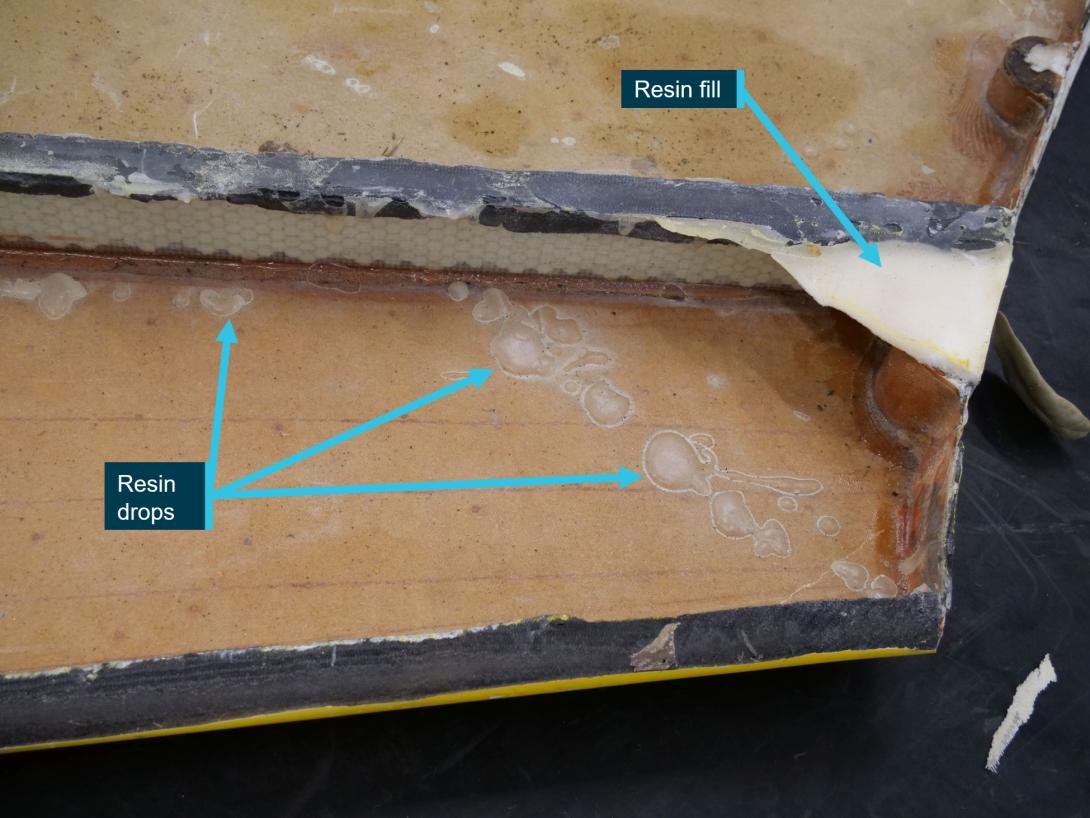
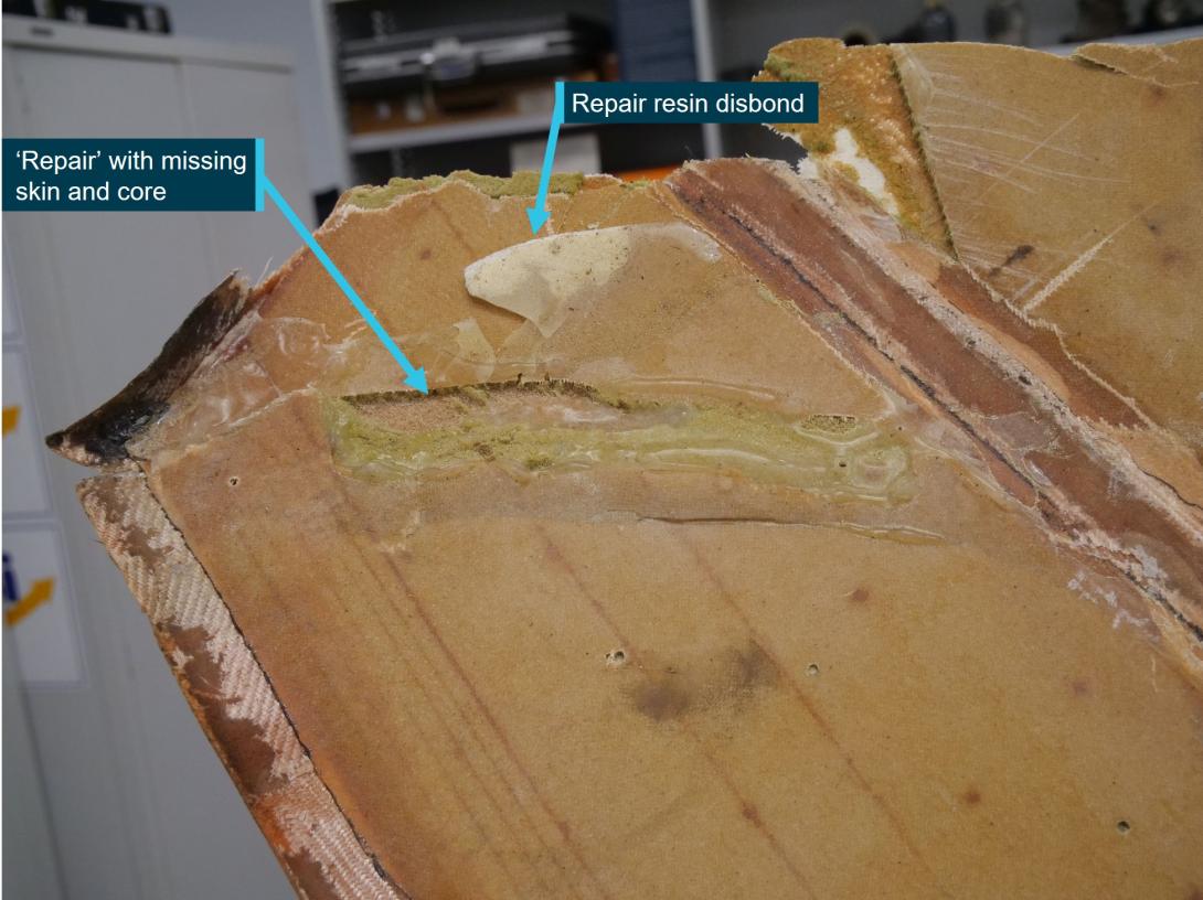
The skin of the tail structure was a sandwich panel consisting of fibreglass skins separated by a foam core. The interior of the left stabiliser had evidence of the reported previous repairs. This included significant amounts of resin fill and drops on the lower skin along the spar (Figure 9). Although there was a considerable amount of resin area at the inboard end of the left spar, none of the upper skin panel remained bonded. There were also areas where the inner fibreglass skin and sections of core were missing and resin had been applied over the top of the damaged structure (Figure 10). One of the larger areas of this type had cracked from one side but was otherwise intact after the accident.
Figure 8: Damage to upper skin of left horizontal stabiliser
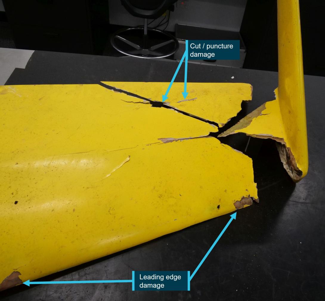
Source: ATSB
Figure 9: Evidence of prior repair with large volume of disbonded resin
Source: ATSB
Figure 10: Repair over core and skin damage
Source: ATSB
Commentary
Rudder shaft fracture
The fatigue cracking of the rudder shaft was the result of fretting fatigue at the areas of highest stress concentration: the sharp corners of the bolt hole. Compared to plain fatigue, fatigue under fretting conditions results in a significant reduction in fatigue life. The progressive wear of the bolt hole and the rudder sleeve would also have resulted in an abnormal loading condition due to the excessive bolt clearance.
The rudder sleeve was the original part, though had been modified. It had been involved in two reported rollover accidents, the most recent of which required manufacture of a new rudder shaft. The condition of the sleeve at the time could not be established, however it was possible that the sleeve had been damaged in one of these events, resulting in deformation of the bolt holes which would have allowed movement and fretting to occur between the components.
Notwithstanding this possibility, the wear and cracking of the rudder shaft was most likely the result of some of the modifications to the original design of the tail assembly during the fitment to G-2468. The most significant was substitution of the original steel rudder shaft for an aluminium component. Although the aluminium component had a slightly larger cross-sectional area (at the bolt hole) than the original steel tube, the steel component would have had considerably superior mechanical properties, including fatigue resistance.
Using a bolt (and hole) with a 25% larger diameter than specified reduced the normal cross‑sectional area of the rudder sleeve and, ordinarily, the shaft. However, because of the other material and dimensional changes to the rudder shaft, the influence of this on the observed damage to the rudder components was not determined.
Similarly, change to the orientation of the rudder bolt may also have altered the normal loading condition of the assembly, however any actual effect was not determined.
Fibreglass repairs
Damage to the tail assembly was largely to the upper surface of the left stabiliser, which was consistent with the ASRA finding that the gyroplane was inverted as it impacted the trees.
Some of the fibreglass repairs on the tail structure were not carried out to a standard that preserved the integrity of the original part. The missing sections of fibreglass skin and core would be detrimental to the strength and stiffness of the structure. Additionally, the large areas of resin that were disbonded from the substrate suggested that those areas of repair likely had a low adhesive strength, which would similarly be detrimental to the structural integrity of the tail.
The nature of the repairs may have influenced the prevalence of post-repair cracking and/or the degree to which the tail broke up during the impact sequence. However, the report that all of the tail structure ended up within a 5-metre radius indicated that it was unlikely that there was a catastrophic failure of the fibreglass structure prior to the initial tree contact.
Summary
Following the limited-scope technical examination, the following conclusions are made with respect to the examination of tail assembly components from the amateur-built gyroplane G-2468:
- The rudder shaft fractured as a result of high cycle fatigue cracking caused by severe fretting.
- An aluminium rudder shaft had been substituted for the original steel part, which made the rudder shaft significantly more susceptible to fatigue cracking.
- There were several other modifications to the original tail design that had the potential to affect the normal loading of the assembly, however the extent of any influence was not determined.
- There was evidence of previous repairs to the fibreglass structure that had not preserved the original structural integrity of the part, however it was unlikely that this resulted in a catastrophic fracture of the tail prior to the impact sequence.
Purpose of safety investigationsThe objective of a safety investigation is to enhance transport safety. This is done through:
It is not a function of the ATSB to apportion blame or provide a means for determining liability. At the same time, an investigation report must include factual material of sufficient weight to support the analysis and findings. At all times the ATSB endeavours to balance the use of material that could imply adverse comment with the need to properly explain what happened, and why, in a fair and unbiased manner. The ATSB does not investigate for the purpose of taking administrative, regulatory or criminal action. TerminologyAn explanation of terminology used in ATSB investigation reports is available here. This includes terms such as occurrence, contributing factor, other factor that increased risk, and safety issue. Publishing informationReleased in accordance with section 25 of the Transport Safety Investigation Act 2003 Published by: Australian Transport Safety Bureau © Commonwealth of Australia 2024 Ownership of intellectual property rights in this publication Unless otherwise noted, copyright (and any other intellectual property rights, if any) in this report publication is owned by the Commonwealth of Australia. Creative Commons licence With the exception of the Coat of Arms, ATSB logo, and photos and graphics in which a third party holds copyright, this publication is licensed under a Creative Commons Attribution 3.0 Australia licence. Creative Commons Attribution 3.0 Australia Licence is a standard form licence agreement that allows you to copy, distribute, transmit and adapt this publication provided that you attribute the work. The ATSB’s preference is that you attribute this publication (and any material sourced from it) using the following wording: Source: Australian Transport Safety Bureau Copyright in material obtained from other agencies, private individuals or organisations, belongs to those agencies, individuals or organisations. Where you wish to use their material, you will need to contact them directly. |
[1] High-cycle fatigue cracking is associated with cyclic loading of a magnitude that produces deformation that is primarily elastic. Fracture due to high-cycle fatigue is typically greater than 10,000 cycles.
[2] Fretting refers to wear resulting from repeated, small, relative displacements in tight-fitting assemblies.
[3] Aluminium with principal alloying additions of magnesium and silicon.
[4] Tolerance on the diameter at the bolted area was 14.93–14.95 mm.
[5] Society of Automotive Engineers alloy designation. 4130 N is a medium carbon steel in the ‘normalised’ condition, which involves heating the steel above the austenite transformation temperature and air cooling. The result is a part with increased ductility and toughness, and reduced internal stresses.


