Executive summary
What happened
On 21 December 2022, at 2108 local time, a Regional Express Saab 340B aircraft departed Perth Airport, Western Australia, for a passenger transport flight to Albany, Western Australia. The flight crew climbed the aircraft to a cruising level of 15,000 feet. Shortly after leveling off, the captain felt 2 bumps pass through the airframe prior to the aircraft noticeably yawing. The flight crew identified a right engine failure, conducted the associated checklists, and secured the right engine. The aircraft was returned to Perth Airport and landed without further incident.
What the ATSB found
The ATSB found that the right engine hydro-mechanical unit was incorrectly seated resulting in a misalignment with the engine’s accessory gearbox. This resulted in significant wear and an eventual decoupling of the hydro-mechanical unit’s drive shaft. The decoupling resulted in a loss of the fuel pump function of the hydro-mechanical unit leading to an in-flight engine failure.
What has been done as a result
The engine manufacturer, GE Aerospace intends to share the learnings of this occurrence with its customers and maintenance facilities and to remind them of the correct installation and maintenance of the hydro‑mechanical unit to prevent premature wear of the drive shaft and accessory gearbox internal shouldered shaft.
Regional Express reported taking several safety actions as a result of this occurrence. These included the dissemination of a technical notice to its engineers highlighting the importance of correct hydro‑mechanical unit installation and the addition of V-band coupling installation to the list of critical control system maintenance items. The operator has also commenced a fleetwide inspection of its aircraft to confirm correct V-band coupling installation. As of 24 July 2024, 50% of the fleet had been inspected with no incorrect installations identified.
Safety message
The incorrect alignment or incorrect seating of an aircraft or engine component may not be readily apparent after the installation of a V-band coupling or clamp. Personnel installing V‑band couplings are reminded to ensure the correct seating and alignment of flanges and the V-band coupling prior to the fitment and torquing of attaching hardware. The incorrect alignment of a component may induce a fault and subsequent failure of a critical component after an extended period of operation.
The investigation
| Decisions regarding the scope of an investigation are based on many factors, including the level of safety benefit likely to be obtained from an investigation and the associated resources required. For this occurrence, a limited-scope investigation was conducted in order to produce a short investigation report, and allow for greater industry awareness of findings that affect safety and potential learning opportunities. |
The occurrence
On 21 December 2022, at 2108 local time, a Regional Express Saab 340B, registered VH RXE departed Perth Airport, Western Australia for a passenger transport flight to Albany, Western Australia. On board were 2 flight crew, 1 cabin crew and 32 passengers. The flight crew consisted of a captain and a first officer. The first officer was the pilot flying and the captain was the pilot not flying.[1]
The flight crew climbed the aircraft and established a direct track to Albany at 15,000 ft. The captain reported that there were no unusual engine indications or engine parameters during the start, take-off, climb and cruise. However, they also recalled that shortly after the cruise was established, they felt the aircraft yaw and 2 bumps pass through the airframe. The captain monitored the engine gauges and observed the right engine’s rpm reducing. The first officer, as pilot flying, commenced the engine failure memory item checklist. The flight crew identified that the right engine had failed.
The captain, as pilot not flying, broadcast a PAN PAN[2] call to air traffic control, advising them of the engine failure and that they were returning to Perth. Due to the unknown nature of the failure, the flight crew elected not to attempt to restart the engine.
After landing at Perth Airport, the flight crew taxied the aircraft off the runway and stopped on a taxiway. The flight crew then requested, via the air traffic control tower, that the aviation rescue fire fighters conduct a visual inspection of the aircraft for any visible oil leaks or hazards that would prevent the aircraft from continuing to taxi. None were observed, and the flight crew taxied the aircraft to the terminal where the aircraft was shut down. After the passengers disembarked, the flight crew and local engineers visually inspected the right engine where a large amount of engine oil was found, pooled in the exhaust. No other faults were observed. There were no injuries to flight crew or passengers.
Context
Flight data recorder
Following the occurrence, the operator provided the ATSB with a download of the flight data recorder (FDR). The download contained the following relevant engine parameters recorded during the occurrence flight:
- gas generator speed
- inter-turbine temperature
- fuel flow
- power lever angle.
A plot of these parameters is displayed at Figure 1 with the following occurrence events identified on the right engine:
- 21:32:38
- gas generator speed began reducing from 92% to 5%
- inter-turbine temperature began reducing from 820°C to 180°C
- fuel flow reduced abruptly to 250 pounds per hour, stabilised with a gradual reduction for approximately 4 seconds, followed by another immediate reduction from 200 to 0 pounds per hour.
- 21:32:58
- power lever angle started to reduce to 55°.
Flight data analysis also identified that the reduction in gas generator speed, inter‑turbine temperature, and fuel flow preceded the power lever reduction by 20 seconds.
Figure 1: Recorded flight data for the occurrence showing selected parameters
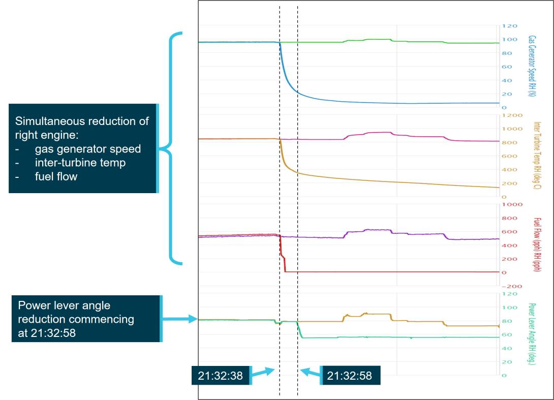
Flight data recorder extract displaying left and right engine parameters. Left engine parameters not labelled.
Source: ATSB
Engines
The Saab 340B is fitted with 2 GE Aerospace CT7-9B turboprop engines driving 4‑bladed propellers. The engine consists of a gas generator powering a free turbine, which is directly coupled to a propeller gearbox. The gas generator has an axial-centrifugal compressor consisting of 5 axial stages and one centrifugal stage. The compressors are driven by a 2-stage gas generator turbine. The propeller is driven by a 2-stage free turbine through a reduction gearbox. Each propeller has full feathering and reversing capabilities. An accessory gearbox (AGB), located on top of the engine, is driven by the gas generator through a radial drive shaft and provides drive for various engine and aircraft accessories (Figure 2).
Hydro-mechanical unit
The hydro-mechanical unit (HMU) provides high pressure metered fuel for combustion. It is attached to the engine AGB and contains a high-pressure fuel pump that is driven by the HMU drive shaft from an internal shouldered shaft within the AGB (Figure 2). This high-pressure fuel pump develops the pressure necessary to spray the fuel into the combustion chamber through the fuel nozzles. Failure of the high-pressure fuel pump will result in an immediate engine flameout.
Figure 2: CT7-9B engine with accessory gearbox
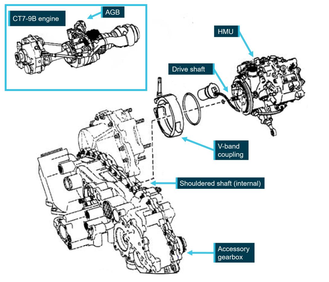
Source: GE Aerospace, annotated by the ATSB
V-band coupling
The HMU is secured to the AGB by a V-band coupling (Figure 2). A V-band coupling consists of a series of V-shaped retainers that are welded to a band, these retainers fit over flanges on the HMU and the AGB. A single nut tightens the band which evenly distributes pressure around the entire circumference of the flanges holding them together. If the coupling is correctly aligned on the flanges, the inner diameter of the band maintains a clearance, known as the apex gap, to the AGB and HMU flanges with flange contact only on the sides of the V-band retainers (Figure 3).
Figure 3: V-band coupling clearance after installation
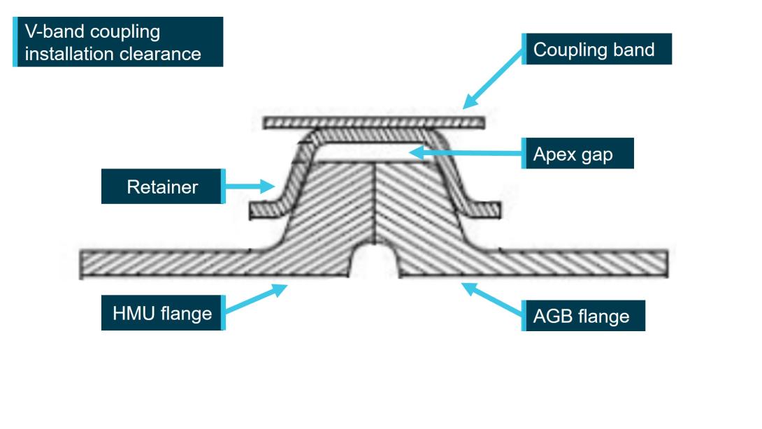
Source: FAA, annotated by the ATSB
Post-occurrence engine inspection
The engine was removed from the aircraft in December 2022 and sent to an authorised CT7 turboprop maintenance facility in Indonesia where it was separated into modules and inspected. These modules were inspected and GE Aerospace provided support for further investigation and analysis. GE provided a report of its findings to the ATSB on 30 April 2024.
During the initial post-occurrence engine troubleshooting, maintenance engineers identified oil in the exhaust and in the compressor discharge pressure (CDP) line. Debris was also identified on the engine power unit chip detector and the B-sump oil scavenge screen (Figure 4). Further troubleshooting by GE Aerospace later identified the debris material as non-ferrous oil coking[3] and not related to the failure of the engine.
GE Aerospace commented that the presence of oil in the exhaust and the compressor discharge pressure line was a result of the engine oil scavenge system depressurising during the in-flight engine shutdown while the core engine continued to be rotated from the relative airflow, circulating oil.
Figure 4: Post engine failure observations
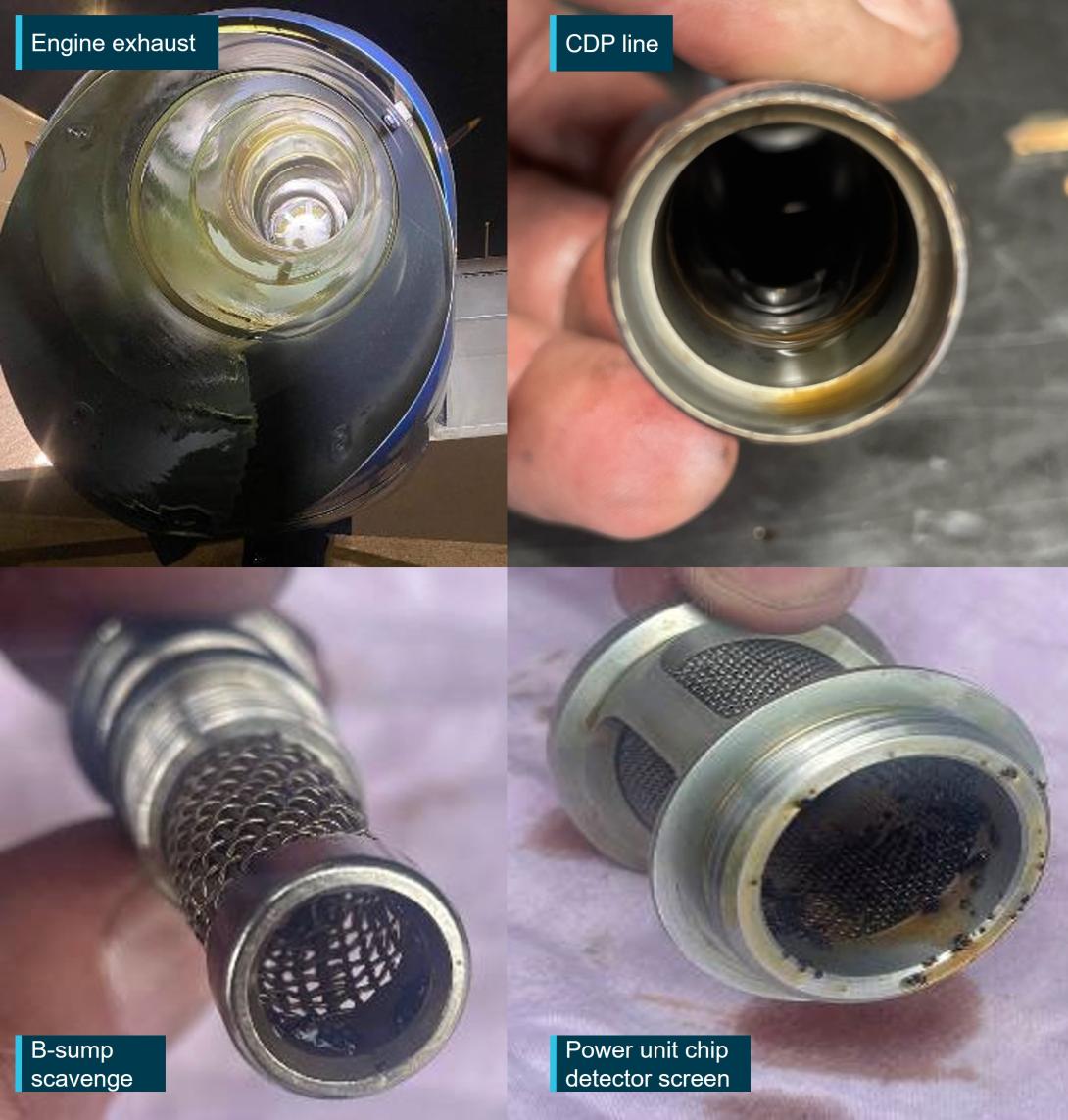
Oil located in engine exhaust and CDP line. Debris located in B-sump scavenge and power unit chip detector screens
Source: Regional Express, annotated by the ATSB
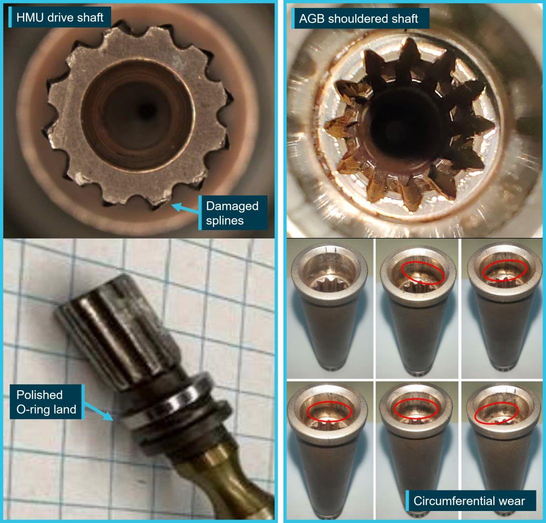
The HMU was removed from the AGB and functionally tested on a test bench with no fault detected. The HMU drive shaft was inspected and was observed to not be bent, however, damage and wear was identified on the spline teeth (Figure 5). An O-ring seal retaining land, located on the HMU drive shaft was observed to be highly polished due to rotational wear.
Figure 5: HMU drive shaft spline and AGB shouldered shaft damage
Source: GE Aerospace, annotated by GE Aerospace and the ATSB
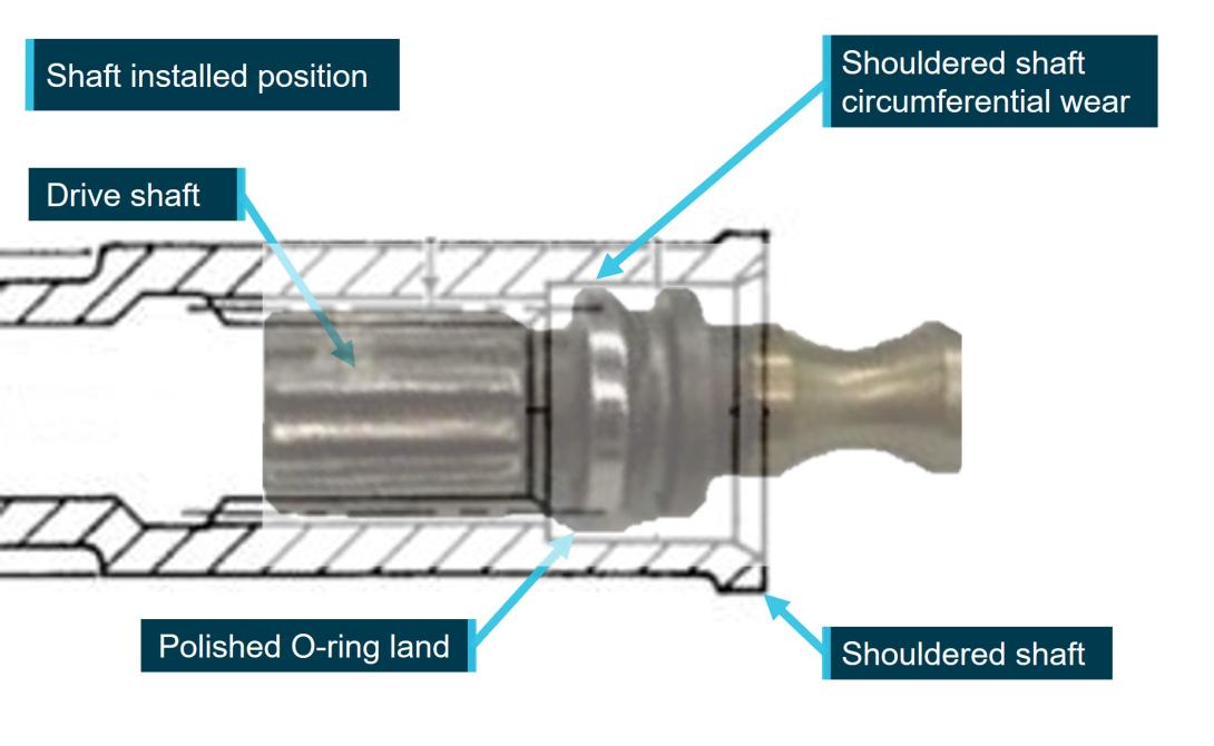
An inspection of the AGB internal shouldered shaft identified deformation wear on the drive shaft spline receptacle along with a circumferential wear mark corresponding with the polished O-ring retaining land position on the HMU drive shaft when assembled (Figure 6). GE Aerospace reported that this was evidence of the drive shaft rotating within the shouldered shaft receptacle as a result of a decoupling.
Figure 6: HMU to AGB drive shaft connection
Source: GE Aerospace, annotated by the ATSB
Measurements were taken of the AGB shouldered shaft inner spline diameter and also of the diameter of the HMU drive shaft spline. These measurements identified that the HMU drive spline’s maximum diameter was less than the minimum diameter for the receptacle splines, indicating a physical inability to be coupled.
The V-band coupling securing the HMU to AGB flanges together was observed to have wear on its inner surface from contact with the AGB flange. This wear was present in an area where, if the HMU and AGB flanges were correctly aligned and seated, the apex gap would be present. Interference wear in this area was evidence of a misalignment and non-seating of the HMU onto the AGB.
Figure 7: HMU V-band coupling wear location
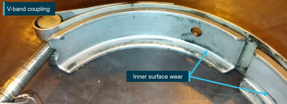
HMU V-band coupling with wear from the AGB flange located on inner surface clearance (apex gap) area
Source: GE Aerospace, annotated by the ATSB
GE Aerospace reported that the coupling was the correct part number for the HMU to AGB coupling. An installation test was also conducted on the V-band coupling with the coupling able to be installed and the nut torqued, with no defects identified.
Damage to the nut and threads was observed on the fuel line that connects the HMU and the fuel filter. A minor dent was also observed on the fuel line sleeve (Figure 8).
Figure 8: HMU fuel line
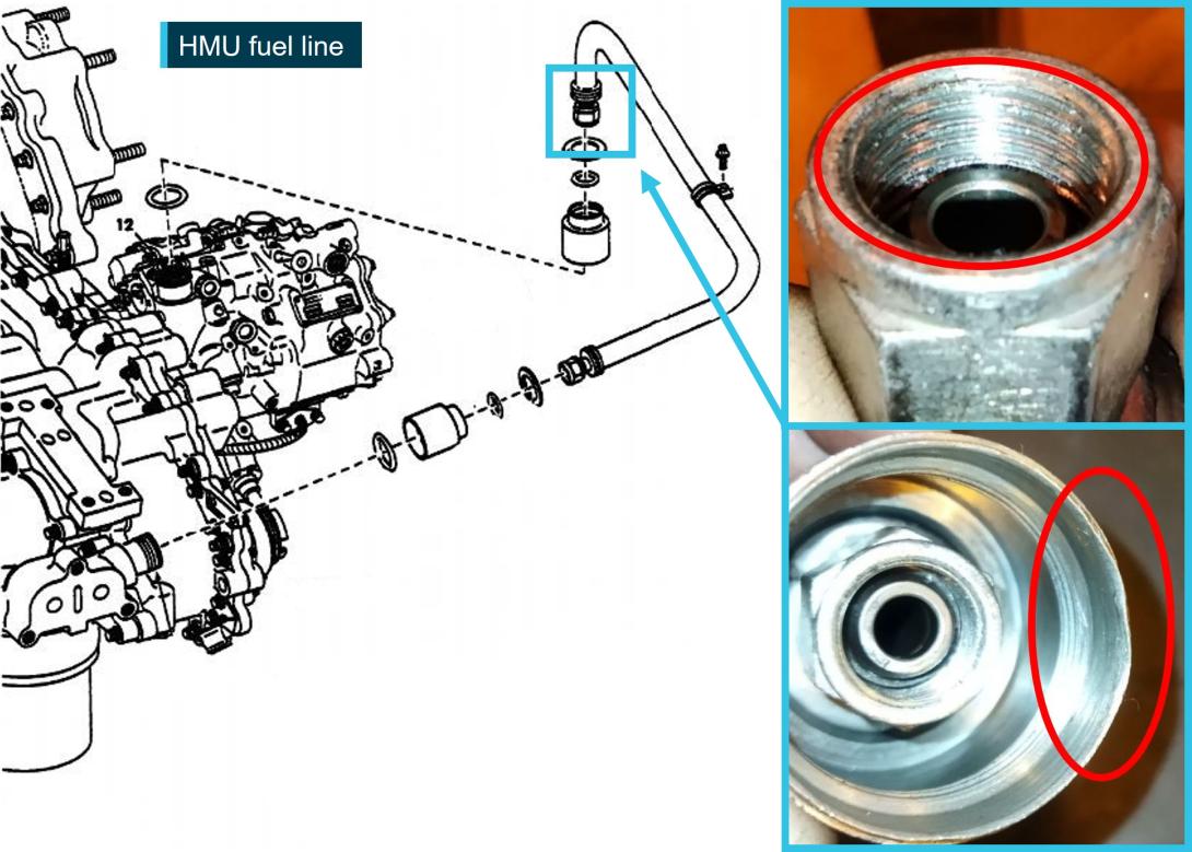
HMU fuel line with wear on thread and dent on sleeve
Source: GE Aerospace, annotated by GE Aerospace and the ATSB
Maintenance history
The last recorded maintenance that required installation of the HMU onto the AGB was during an engine workshop visit at an offshore maintenance facility in February 2018. There was no further record of removal or installation of the HMU by the operator in the engine or aircraft maintenance log after this date. From February 2018 to the occurrence flight, the engine accumulated a total time of 4,816 hours and 5,331 cycles.
Safety analysis
On 21 December 2022, at 2108 local time, a Regional Express Saab 340B departed Perth Airport, Western Australia, for a passenger transport flight to Albany, Western Australia. During cruise the right engine failed, and the aircraft was returned to Perth.
Post-occurrence troubleshooting, component testing, examination and analysis were conducted on the right engine. Wear and deformation were identified on the splines of the HMU drive shaft and the internal splines of the AGB shouldered shaft.
Significantly, the polished O-ring land on the HMU drive shaft and the corresponding circumferential wear marks within the AGB shouldered shaft indicated that the drive shaft had decoupled and was spinning within the shouldered shaft during operation. Damage identified on the HMU drive shaft splines, along with corresponding wear and damage to the AGB shouldered shaft receptacle also indicated that rotation had occurred between the 2 shafts. Additionally, the measured minimum internal diameter between the splines of the AGB shouldered shaft receptacle was larger than the maximum HMU spline diameter, indicating a physical impossibility of the AGB to drive the HMU.
When the HMU was functionally tested, no faults were detected with the HMU and the high‑pressure fuel pump. The most likely reason for serviceable operation during testing was that the HMU drive shaft was being driven by the shouldered shaft of the test stand and not the worn shouldered shaft within the engine’s AGB.
Wear marks from the AGB flange were observed on the inner surface of the V-band coupling. These wear marks were located on an area of the coupling that, when the flanges of the HMU and AGB are correctly aligned and the coupling is aligned correctly prior to and during torquing, an apex gap is maintained between the flanges and the inner surface of the V-band coupling. The presence of interference wear marks on the inner surface of the V‑band coupling demonstrated that the flanges, or the V-band coupling, were misaligned during installation.
Also noted during the post-occurrence inspections was damage to the threads on the fuel line that connected to the HMU. This line was connected as part of the HMU installation and the presence of damage to the threads was a possible further sign of the fuel line being connected to a misaligned HMU.
This misalignment of the HMU, taking into consideration that the HMU drive shaft was not bent, likely translated to an uneven loading of the splines of the HMU drive shaft and the AGB shouldered shaft receptacle during operation. This in turn probably caused wear, damage, and subsequent decoupling of the HMU drive shaft during operation.
Findings
|
ATSB investigation report findings focus on safety factors (that is, events and conditions that increase risk). Safety factors include ‘contributing factors’ and ‘other factors that increased risk’ (that is, factors that did not meet the definition of a contributing factor for this occurrence but were still considered important to include in the report for the purpose of increasing awareness and enhancing safety). In addition ‘other findings’ may be included to provide important information about topics other than safety factors. These findings should not be read as apportioning blame or liability to any particular organisation or individual. |
From the evidence available, the following findings are made with respect to the engine failure involving Saab 340B, VH RXE, 141 km south of Perth, Western Australia on 21 December 2022.
Contributing factors
- An incorrectly seated and misaligned hydro-mechanical unit resulted in significant wear of the hydro-mechanical unit drive shaft and accessory gearbox internal shouldered shaft. This resulted in the hydro-mechanical unit slipping and decoupling from the engine accessory gearbox.
- The slipping and decoupling of the hydro-mechanical unit drive shaft from the engine accessory gearbox resulted in a loss of fuel pump function and metered fuel output, leading to a failure of the engine.
Safety actions
| Whether or not the ATSB identifies safety issues in the course of an investigation, relevant organisations may proactively initiate safety action in order to reduce their safety risk. All of the directly involved parties are invited to provide submissions to this draft report. As part of that process, each organisation is asked to communicate what safety actions, if any, they have carried out to reduce the risk associated with this type of occurrences in the future. The ATSB has so far been advised of the following proactive safety action in response to this occurrence. |
Safety action by GE Aerospace and Regional Express
GE Aerospace advised that it intended to share the learnings of this occurrence with its customers and maintenance facilities and to remind them of the correct installation and maintenance of the hydro-mechanical unit to prevent a reoccurrence and premature wear of the drive shaft and accessory gearbox internal shouldered shaft.
Regional Express reported a number of safety actions taken as a result of this occurrence. These include the dissemination of a technical notice to its engineers highlighting the importance of correct hydro‑mechanical unit installation and the addition of V-band coupling installation to the list of critical control system maintenance items. The operator has also commenced a fleetwide inspection of its aircraft to confirm correct V-band coupling installation. As of 24 July 2024, 50% of the fleet had been inspected with no incorrect installations identified.
Sources and submissions
Sources of information
The sources of information during the investigation included:
- the captain of VH-RXE
- Airservices Australia
- Regional Express Pty Ltd
- GE Aerospace.
Submissions
Under section 26 of the Transport Safety Investigation Act 2003, the ATSB may provide a draft report, on a confidential basis, to any person whom the ATSB considers appropriate. That section allows a person receiving a draft report to make submissions to the ATSB about the draft report.
A draft of this report was provided to the following directly involved parties:
- the captain of VH-RXE
- Regional Express Pty Ltd
- GE Aerospace
- Saab Aircraft Company
- Civil Aviation Safety Authority.
Submissions were received from:
- Regional Express Pty Ltd
- GE Aerospace
The submissions were reviewed and, where considered appropriate, the text of the report was amended accordingly.
Purpose of safety investigationsThe objective of a safety investigation is to enhance transport safety. This is done through:
It is not a function of the ATSB to apportion blame or provide a means for determining liability. At the same time, an investigation report must include factual material of sufficient weight to support the analysis and findings. At all times the ATSB endeavours to balance the use of material that could imply adverse comment with the need to properly explain what happened, and why, in a fair and unbiased manner. The ATSB does not investigate for the purpose of taking administrative, regulatory or criminal action. TerminologyAn explanation of terminology used in ATSB investigation reports is available here. This includes terms such as occurrence, contributing factor, other factor that increased risk, and safety issue. Publishing informationReleased in accordance with section 25 of the Transport Safety Investigation Act 2003 Published by: Australian Transport Safety Bureau © Commonwealth of Australia 2024
Ownership of intellectual property rights in this publication Unless otherwise noted, copyright (and any other intellectual property rights, if any) in this report publication is owned by the Commonwealth of Australia. Creative Commons licence With the exception of the Coat of Arms, ATSB logo, and photos and graphics in which a third party holds copyright, this publication is licensed under a Creative Commons Attribution 3.0 Australia licence. Creative Commons Attribution 3.0 Australia Licence is a standard form licence agreement that allows you to copy, distribute, transmit and adapt this publication provided that you attribute the work. The ATSB’s preference is that you attribute this publication (and any material sourced from it) using the following wording: Source: Australian Transport Safety Bureau Copyright in material obtained from other agencies, private individuals or organisations, belongs to those agencies, individuals or organisations. Where you wish to use their material, you will need to contact them directly. |
[1] Pilot flying and pilot not flying: procedurally assigned roles with specifically assigned duties at specific stages of a flight. The pilot flying does most of the flying, except in defined circumstances; such as planning for descent, approach and landing. The pilot not flying carries out support duties, such as radio communications, and monitors the pilot flying’s actions and the aircraft’s flight path.
[2] PAN PAN: an internationally recognised radio call announcing an urgency condition which concerns the safety of an aircraft or its occupants but where the flight crew does not require immediate assistance.
[3] Coking: A build-up of carbon deposits in the engine oil over time, as a result of a constant heating and cooling of the oil.


