Executive summary
What happened
On 22 September 2019, when approaching the Andoom loading station, near Weipa, Queensland, the driver of the RTA Weipa bulk ore train applied various braking configurations, but the train did not slow. Consequently, when travelling at about 37 km/h, the empty ore train collided with the partially loaded rake of wagons at the loading station. The locomotive (R1006) and 4 empty wagons at the rear of the partially loaded rake, derailed on impact. The collision resulted in the leading end modular driver’s operating cabin being crushed and separating from the main structure of the locomotive, coming to rest on the ground. It also resulted in the last wagon of the rake splitting in half. The driver’s cabin sustained substantial damage. The driver was initially trapped inside the cabin but received only minor injuries.
What the ATSB found
The ATSB established that, during the coupling process, the pneumatic brake pipe cock was not opened between the locomotive and wagons preventing continuity of air through the train’s brake pipe. This resulted in the wagon brakes not operating when commanded, only leaving the locomotive brakes operational. Consequently, when approaching the loading point, the driver applied the train brake, however, the train did not respond as expected.
The manual brake continuity test was not completed during the pre-departure check as part of the coupling process, which removed an opportunity to detect that the pneumatic brake pipe cock to the wagons had not been opened. The process being used was inconsistent with the published procedure for the brake continuity testing.
While the operator had routinely conducted audits at Weipa, these audits had not detected that the brake continuity test procedure was being applied inconsistently among the drivers. Further, while the operator had change management processes in place, these processes were not applied when the end of train telemetry system became inoperable and the Lorim Point dump station was automated. There were missed opportunities to review the adequacy of the existing procedures.
The manual brake continuity test required 2 competent staff, however, there was no procedure in the operations manual to ensure that a second person was present to assist the driver with the test.
During the collision sequence, the modular cabin mount retention pockets failed due to material overload, allowing the cabin to fold back on itself, into the locomotive structure behind, and become dislodged from the locomotive frame. This compromised the survivable space within the cabin afforded by the collision posts. The ATSB found that the design of the modular cabin mount was not resilient to frontal impact forces in the event of a collision. Also, the Rail Industry Safety Standards Board did not provide design and/or performance standards on modular cabin resilience and retention for locomotive crashworthiness.
What has been done as a result
RTA Weipa Pty Ltd have installed a revised telemetry system and confirmed functionality. This allows the driver to perform brake continuity tests without relying on a second person to assist with the manual procedure. In addition, they have also introduced safety improvements to the manual brake continuity testing and all relevant team members were re-trained in the continuity brake test requirements, as per the Railway Operational Procedures Manual.
The new owner of the locomotive design, Progress Rail, have re-engineered the modular cabin mounts to improve strength to reduce the risk of cabin separation in the event of a collision.
The Rail Industry Safety Standards Board included modular cabin retention within the update to Australian Standard 7520 that had already been underway.
Safety message
This accident highlights the importance of ensuring that published rules and procedures are followed, through an effective monitoring and audit process, which is fundamental to rail safety. Likewise, changes to rail operations need to be adequately managed to identify new or altered risks.
Further, in the event of an accident, the preservation of survivable space is critical. Without a recognised design and/or performance standard, it is difficult to measure the adequacy and effectiveness of current and redesigned crashworthiness systems.
The occurrence
The connection at Lorim Point
On 22 September 2019, at about 0330 Eastern Standard Time,[1] a production train driver (driver) signed-on for duty to commence operating trains for RTA (Rio Tinto Aluminium) Weipa Pty Ltd between the Andoom loading station and Lorim Point dump station, near Weipa, Queensland. The driving task involved locomotive R1006 hauling loaded ore wagons (rake)[2] from the loading station to the dump station, 19.5 km away (Figure 1). The locomotive would leave the loaded rake at Lorim Point for unloading, and then attach to an awaiting empty rake to take it away back to the Andoom loading station.
Figure 1: Location of Andoom and Lorim Point
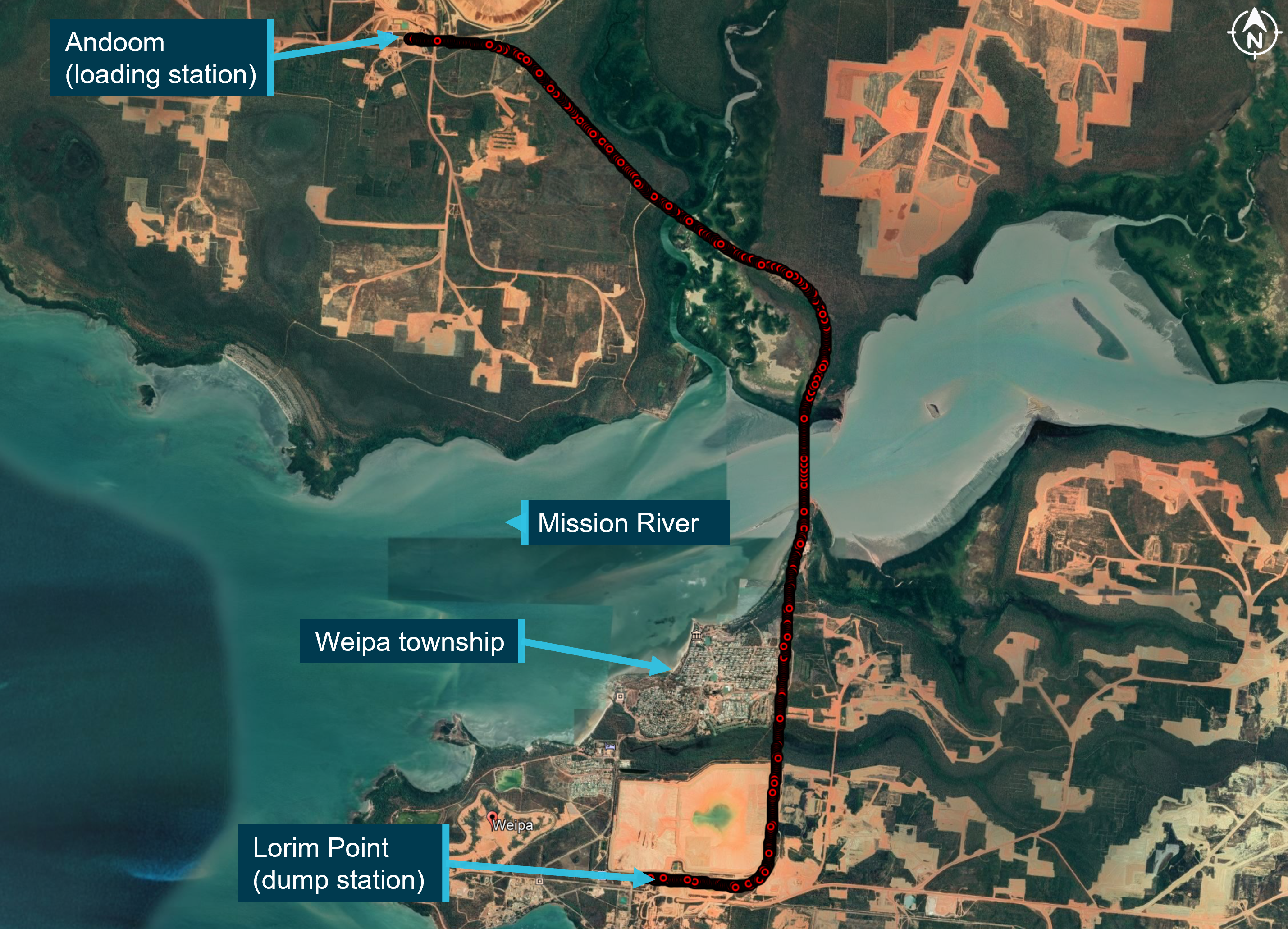
Source: Google Earth, annotated by the ATSB
The cameras used for remotely monitoring the wagons at the automated dump station at Lorim Point were not operational on the day of the occurrence, meaning that a person had to be present. Earlier that morning (at 0830), the fixed plant crew leader had made their way to the dump station, although they had been called away on another task before the train arrived.
At about 0903, the train arrived at the Lorim Point dump station. The driver commenced the procedure of detaching the locomotive from the loaded rake (rake 1) and attaching to the empty rake (rake 3). After detaching the loaded rake, the driver moved the locomotive away, past the dump pit toward the empty rake, as shown from the locomotive video in Figure 2.
Figure 2: Locomotive at the Lorim Point dump station detaching rake 1
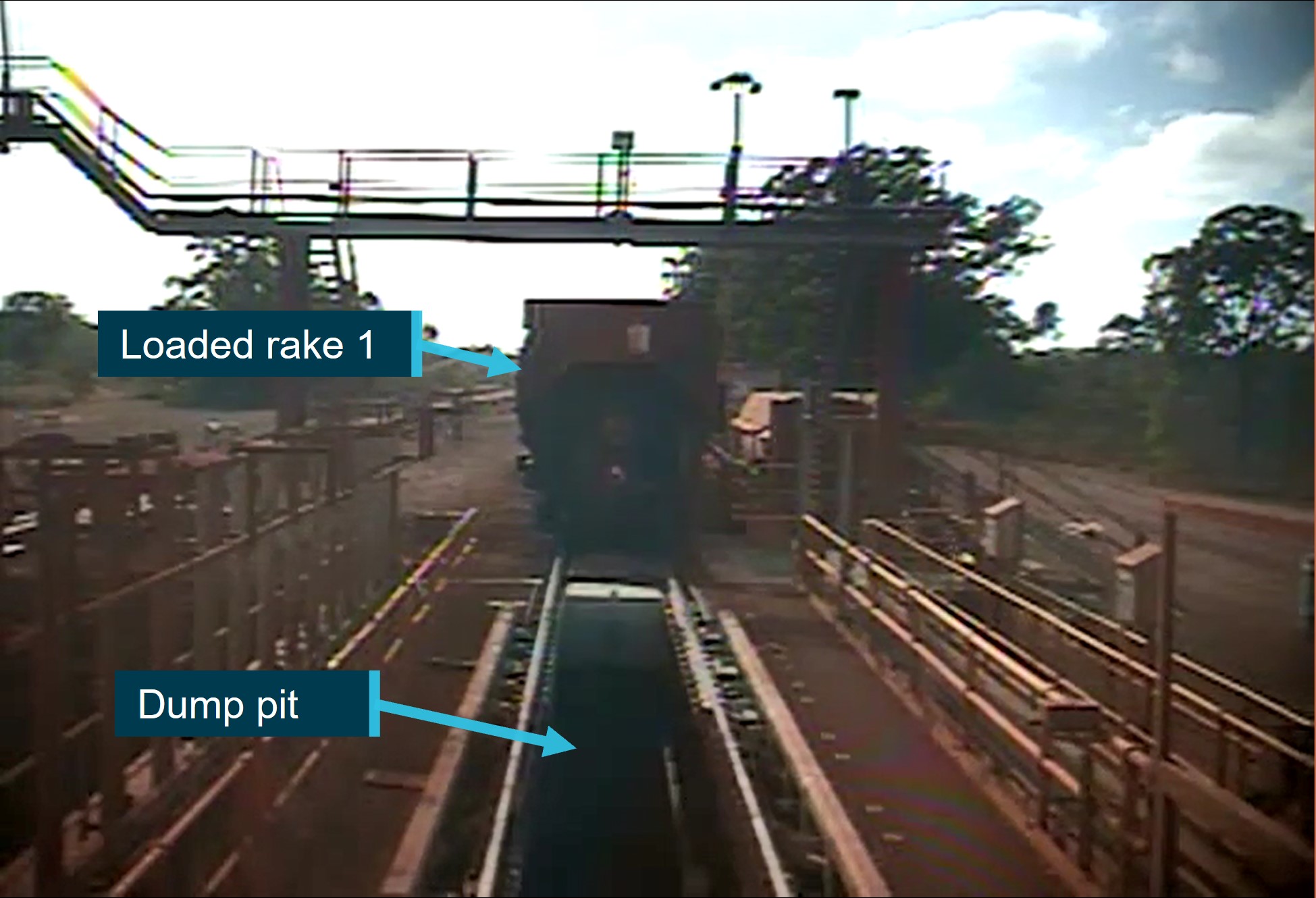
Source: RTA Weipa Pty Ltd, annotated by the ATSB
The locomotive was coupled with the empty rake, then moved to perform a stretch test to check the integrity of the coupling. Once successfully tested, the driver secured the locomotive by placing the reverser handle in the neutral position, applying the independent brake, selecting the generator field switch off, and reducing the brake pipe pressure by 100 kPa.[3]
At about this time, the driver noticed the fixed plant crew leader arrive back at the dump station. The driver gestured to the fixed plant crew leader who responded and began assisting with the coupling process.
The driver transferred control from cabin 2 to cabin 1,[4] then exited cabin 2 and started walking toward cabin 1. The fixed plant crew leader recalled connecting the brake pipe hoses, opening both brake pipe cocks simultaneously and slowly, hearing the equalisation ‘hiss’ of air, then setting the auxiliary air compressor to transit. Once done, the fixed plant crew leader gave a ‘thumbs up’ to the driver, then moved clear and walked to the dump station office.
After receiving the thumbs up from the fixed plant crew leader, the driver reported they checked the brake pipe pressure was as expected via the in-cabin gauge on the functionality integrated railroad electronics screen. Shortly following this, the driver released the brakes and the train was pushed back from the dump station clear of the number 13 points. Ordinarily, when past the number 13 points, the driver would stop the train with the locomotive just clear of the points and associated signal. The driver would then drive forward (pulling the rake) to Andoom on the adjacent main line via the number 13 points. On this occasion, the driver made a (more than expected) train brake application to stop the train, but had to supplement this with the locomotive independent brake as the train brake was not sufficient. Subsequently, the train stopped further beyond the number 13 points than normal (Figure 3 left).
The driver moved the train forward (pulling the rake) to the usual standing position just clear of number 13 points and signal (Figure 3 right). At this time, the driver dismissed the braking anomaly as a consequence of an auxiliary compressor issue that had not fully recharged the braking system on the rake. The driver deduced that, since the rake was connected to the locomotive, the locomotive compressor would fully recharge the rake brakes (auxiliary reservoir) and it would be checked at Andoom.
Figure 3: Empty train stopped further beyond the number 13 points (left) and moving forward to Andoom (right)
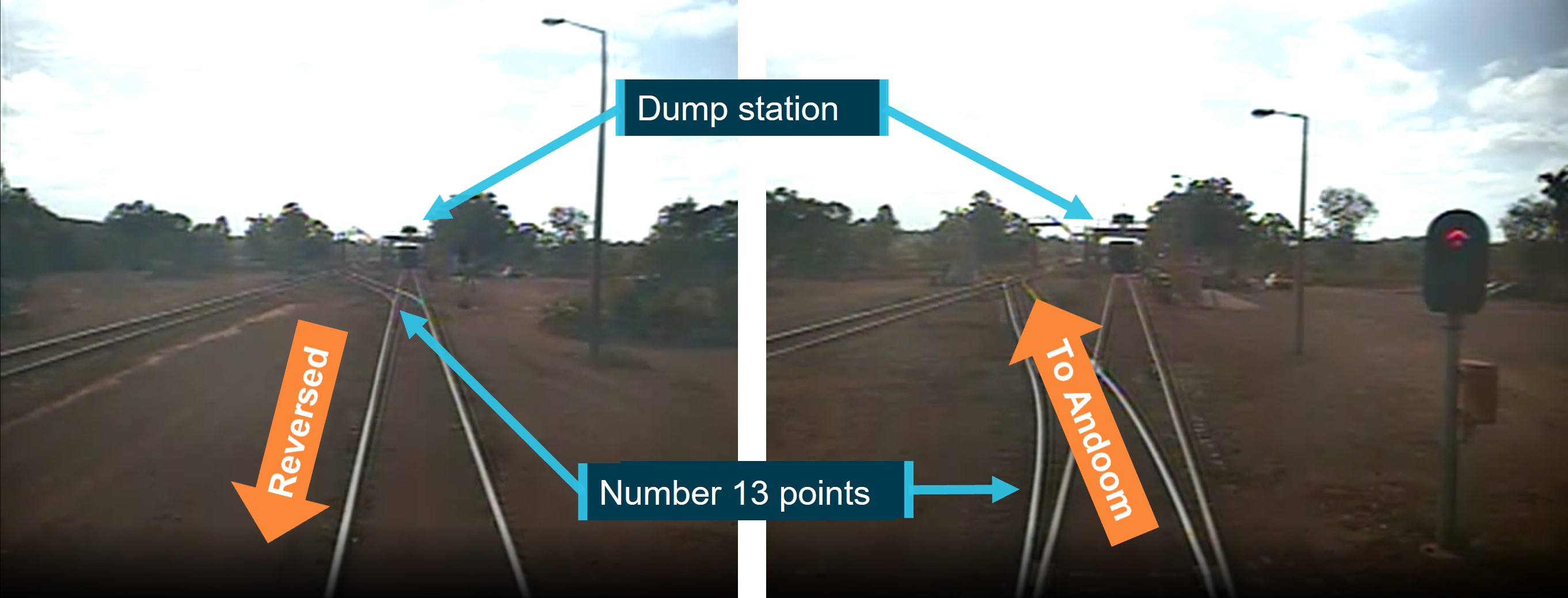
Source: RTA Weipa PTY Ltd, annotated by the ATSB
At about 0910, the driver released the brakes and commenced accelerating through the number 13 points, onto the main line towards Andoom. Several minutes later, the train past locomotive R1005 (machinery move train) in the siding, and continued towards Andoom at up to 65 km/h, the prescribed speed limit. Other than a minor brake pipe pressure reduction passing R1005, no other brake applications were noted in the locomotive data. The journey towards Andoom was uneventful. Throughout the trip, the driver routinely reported back to the safe working driver,[5] located on R1005. Just prior to approaching the regular braking point, the driver reported to the safe working driver while passing the 16.5 km marker at 0930.
The collision at Andoom
At the 17.5 km marker, travelling at 64 km/h, the driver made a service brake[6] application to slow the train for the 25 km/h turnout on the approach to Andoom. This was about 1,300 m before a rake of wagons (rake 2) being loaded at the Andoom loading point. However, the brake application did not slow the train. In response, the driver released the brake, applied the dynamic brake[7] on the locomotive, and again attempted to apply a service brake application. During this sequence, the train passed the turnout signal (about 970 m before rake 2) at about 62 km/h. Recognising the train was not slowing enough for the turnout, the driver made an emergency brake application,[8] which was not effective at reducing speed and did not perform as the driver expected.
The train passed through the turnout at 54 km/h, above the 25 km/h limit. At that time, the end of rake 2, at the Andoom loading point was 635 m beyond the turnout. At about 300 m from rake 2, the driver applied the locomotive independent brake to slow the train. As the independent brake only applies on the locomotive, there was only a slight decrease in train speed. The driver was aware that a train collision was imminent but was unable to prevent it despite different combinations of brake commands (Figure 4). During this period, the driver contacted the control centre by radio and advised them of the circumstances.
Figure 4: Front of train video capture just prior to the collision
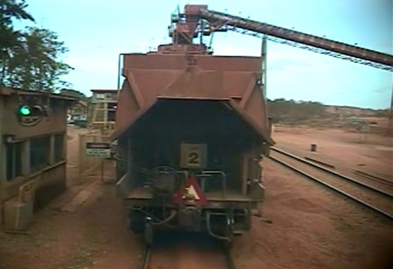
Source: RTA Weipa Pty Ltd, annotated by the ATSB
At 0933, while travelling at about 37 km/h, the train collided with the partially loaded rake of wagons (rake 2). Locomotive R1006 and 4 empty wagons at the rear of rake 2 derailed on impact. The collision resulted in the leading end modular driver’s operating cabin 1 separating from the main structure of the locomotive, coming to rest on the ground. The driver was initially trapped inside the cabin but received only minor injuries.
Post-accident examination
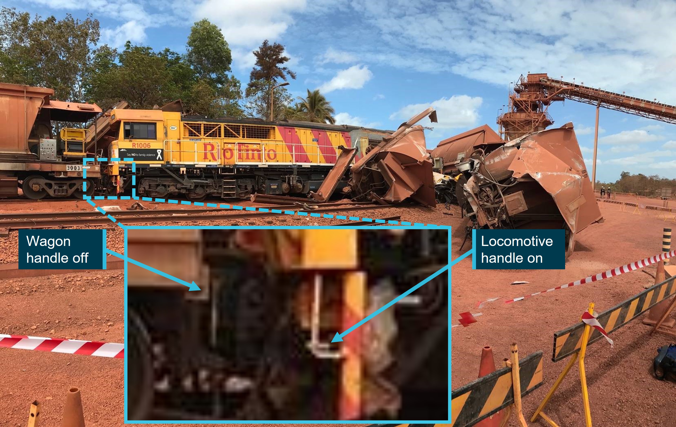
An examination of the wreckage found that the pneumatic brake pipe cock was open on the locomotive (Figure 5 ‘locomotive handle on’) but closed on the wagon directly behind the locomotive (Figure 5 ‘wagon handle off’). This configuration would prevent continuity of air through the train’s brake pipe.
Figure 5: Position of brake pipe cocks on the locomotive (right) and following wagon (left)
Source: RTA Weipa Pty Ltd, annotated by the ATSB
Context
Personnel information
Driver
The driver had driven ore trains in Weipa since 1996, worked in the plant, then returned to full-time driving in 2006. The driver was qualified to perform the role, holding a Certificate III in Transport and Logistics (Rail Operations), and had undergone regular refresher and reassessment training, most recently in April 2019. RTA Weipa Pty Ltd Train Drivers Reassessment Tool conducted in April 2019 included questions relating to brake pipe continuity and brake tests, which were answered correctly by the driver.
An examination of the driver’s records confirmed that their health assessment was current and that they met the required standard. There was no evidence to suggest that any medical or physiological factors affected the driver’s performance on the day. Further, a review of the driver’s sleep and roster information found it was highly unlikely that they were experiencing levels of fatigue known to have an adverse effect on performance.
Fixed plant crew leader
The fixed plant crew leader had commenced with RTA Weipa Pty Ltd in 2009 as a plant operator, which included initial and refresher training for coupling and uncoupling trains. The most recent refresher training was completed in December 2016 and included questions relating to brake pipe continuity, and brake tests associated with coupling and uncoupling trains tests, which were answered correctly. The next refresher training was due in 2018, however, this did not occur. In 2018, the individual was promoted to fixed plant crew leader and this role did not require that competency to be refreshed, nor the couple or uncouple task to be performed. The fixed plant crew leader indicated that, as a plant operator, they had performed thousands of coupling and uncoupling tasks.
An examination of the fixed plant crew leader’s records confirmed that their health assessment was current and that they met the required standard. There was no evidence to suggest that any medical or physiological factors affected their performance on the day. Further, a review of the leader’s sleep and roster information found it was highly unlikely that they were experiencing levels of fatigue known to have an adverse effect on performance.
Train information
Locomotives
RTA Weipa Pty Ltd utilised 2 JT42C diesel-electric locomotives (R1005 and R1006), each with a rated tractive power of 3,000 hp, total length of 22 m, and weight of 128 t. The locomotives were built by Downer EDI Rail[9] and entered service in 2009. The locomotive design was specified as JT42C, with twin modular driver’s cabins, which was based on widely used designs. Although the locomotives were capable of travelling up to 100 km/h, the speed was restricted to a maximum of 65 km/h on this network. At the time of this accident, there were about 473 locomotives fitted with modular cabins in service on Australian rail networks, equating to about 21% of the total locomotive fleet.
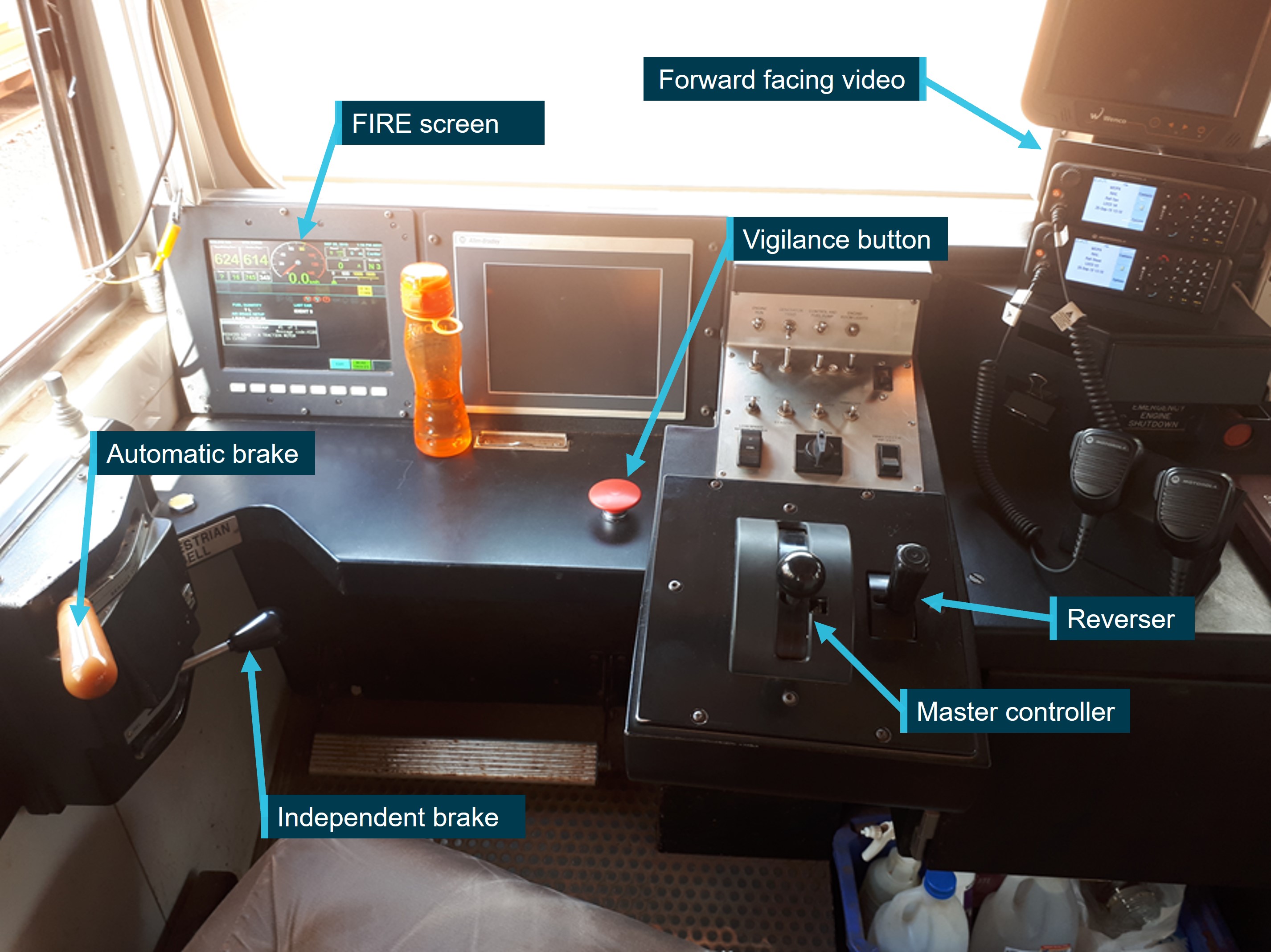
The 2 operating cabins on the accident locomotive (R1006), one on either end, were fitted with identical operating controls (Figure 6). Each cabin was fitted with:
- functionality Integrated Railroad Electronics (FIRE) screen
- wagon telemetry system
- vigilance system
- forward facing video
- radio communication equipment
- master controller (throttle and dynamic braking)
- automatic air brake
- independent air brake
- park brake.
In addition, the locomotive was fitted with a single locomotive data recorder covering both cabins.
Figure 6: Locomotive cabin, representative of locomotive R1006
Source: RTA Weipa Pty Ltd, annotated by the ATSB
A review of the locomotive logs and maintenance history found there were no defects known to have an adverse effect on braking performance.
Collision protection systems
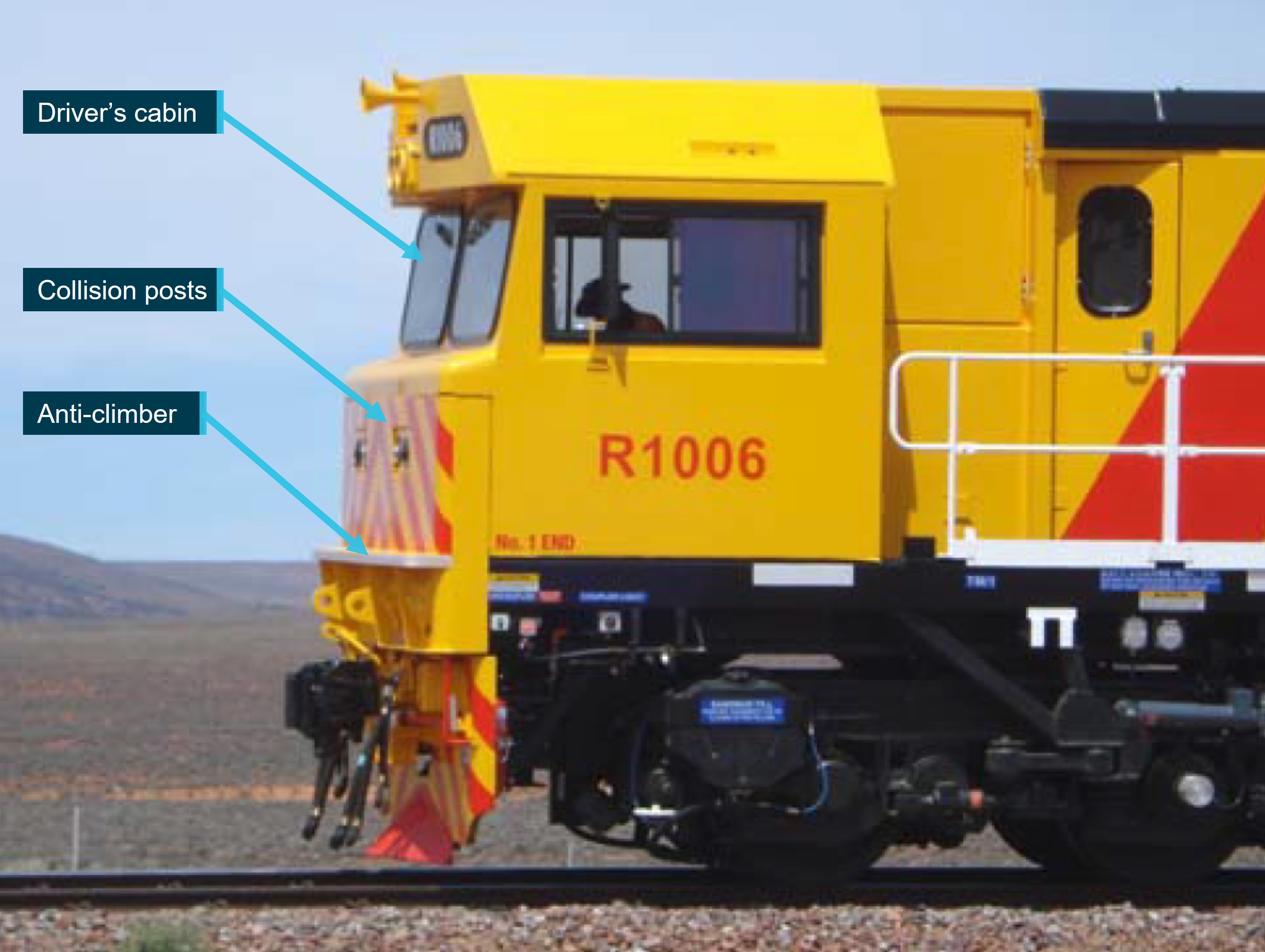
The locomotive was fitted with an anti-climber and collision posts (Figure 7). In the event of a collision with another rail vehicle, the anti-climber device prevented the locomotive from riding over the top of the other vehicle during an impact. When fitted to both locomotives involved in a collision, the anti‑climber features would engage and resist any relative vertical movement. The anti-climber was complimented by the collision posts to prevent telescoping, where a rail vehicle body breaches the end structure of another rail vehicle and passes into the occupied space.
The driver’s cabin had a collision steel frame reinforced with 6 vertical support members welded to the top of the underframe at each end to protect the lower part of the cabin. This collision protection extended to the window height of the cabin.
Figure 7: Locomotive collision protection systems
Source: RTA Weipa Pty Ltd, annotated by the ATSB
Rolling stock
RTA Weipa Pty Ltd transported raw bauxite ore via top loading, bottom dumping hopper wagons. Each wagon had a tare weight of 20 t and gross weight of 100 t. Generally, ore wagons were assembled into 3 rakes, each with 34 wagons, via automatic couplers with flexible pneumatic hoses and connectors with isolating cocks.
Brake and control systems
Braking systems
Train speed is controlled by the operating driver, through the application (either combined or singularly) of the automatic air brake, independent locomotive brake, dynamic brake, and throttle.
A service brake application was used for normal operation of the train’s brake. Applying the service brake required a reduction in the brake pipe pressure between 50 kPa (minimum application) and 170 kPa (full application). When the brakes were released, the brake pipe pressure increased to the 620 kPa.
The dynamic brake provides braking effort by reversing the function of the locomotive’s electric traction motors. The motors act as generators with the mechanical (braking) effort required to turn the motors being converted to electrical energy, which is subsequently dissipated through electrical resistor banks on the locomotive roof. The driver controls dynamic braking via the locomotive master controller.
A brake pipe running the length of the train and containing compressed air from the locomotive, is used to apply and release the air brakes on each wagon. Driver commands through the automatic brake handle regulate the air pressure in the brake pipe that runs the length of the train. Any reduction in brake pipe air pressure from the nominal 620 kPa results in the train brake applying, including the locomotive. Put simply, the more the air pressure is reduced below the nominal pressure in the brake pipe, the more the train brakes apply (up to a full-service application). The number of brake applications over a given period is limited to the volume of air in the auxiliary reservoir (located on each wagon), actuation of the brake cylinders, and the amount of recharging from the brake pipe between applications. Safe driving practice maximises the recharging of the auxiliary reservoir between applications.
Regulating the brake pipe pressure using the automatic brake handle will apply brakes to both the locomotive and the wagons. The driver may choose to ‘bail off’ (remove) the application of the locomotive’s brakes by pushing the independent brake handle down. Alternatively, the automatic brake handle can be left in the release position (maintaining full brake pipe pressure) and the driver may apply brakes only on the locomotive by moving the independent brake handle forward.
In emergency situations, the driver may move the automatic brake handle into the emergency position, resulting in a rapid depletion of the brake pipe air pressure and maximum brake application. Similarly, if the train separates, or the brake pipe is interrupted, the air will rapidly deplete resulting in maximum brake application.
Auxiliary air compressor
During transit operations between Andoom and Lorim Point, pressurised air is supplied to the brake pipe via the locomotive air compressor. However, when loading or discharging the ore there is no locomotive attached. Compressed air is instead provided via an auxiliary compressor located on each rake. The auxiliary compressor maintained the rake brake pipe pressure at a nominal 620 kPa, which keeps the wagon brakes released. This allowed the indexing arms on the dump machine to engage with the rake to move it over the dump pit.
When the locomotive was connected to the rake, the auxiliary compressor was switched to transit mode so that it did not interfere with brake commands from the locomotive when in transit.
Telemetry system
The telemetry system is a device secured to the coupler of the last vehicle, which communicates via radio link to the locomotive and provides real time end-of-train air pressure and other related information. RTA Weipa Pty Ltd stated that the purpose of the system was to expediate the rake changeover procedure and improve efficiency.
The system was intended to operate using one locomotive, 3 compressor wagons and 3 end of rake wagons powered up at the one time. The telemetry modules were in each of the compressor and end of rake wagons, and continually monitored brake pipe and brake cylinder pressures. This ensured that brake pipe continuity existed throughout the entire rake of wagons. If the system failed, a manual back-up system was in place that could be operated via an override switch on each compressor wagon.
The system allowed for 3 modes of operation: load, transit and dump. Their functions were:
- Load – applies the automatic brake and operates the dump door exhaust solenoid and supplies air to the wagon brake pipe.
- Transit – releases the automatic brake and operates the dump door exhaust solenoid but does not supply air to the wagon brake pipe.
- Dump – applies the automatic brake and operates the dump door pressure solenoid and supplies air to the wagon brake pipe.
This meant that, during loading and unloading, when the locomotive has been detached, brake pipe air pressure was maintained by one of the compressor wagons when the load or dump mode had been selected. When coupled to the locomotive, air was supplied to the wagon braking system by the locomotive. By using the telemetry control buttons, or by manually setting a valve on the compressor wagons using the manual override switch, the air supply could be changed from the locomotive to the compressor wagon.
When the locomotive was commissioned (in early 2008), the original telemetry system was installed by RTA Weipa Pty Ltd on its arrival to Weipa. This system was operational, however, was found not to be reliable. In 2016, a decision was made to change to another system with similar functionality. The sourcing and purchasing of the new design took until 2017. The original system was removed in September 2017 and the new one installed,[10] however, it did not operate as per design. The changes made to the locomotives and wagons made it too costly to reinstall the original system, and a decision to progress with the new system was made.
At the time of the accident, the system was working within the rakes, but there was no radio signal into the locomotive. The telemetry upgrade was in a transition phase with the intention of using the same operating system as the original installation, but upgrading the radios and programmable logic controllers. This meant that the driver could not perform the brake continuity testing from the locomotive cabin, instead reverting to a manual pre-departure procedure contained in the Rio Tinto Weipa Railway Operational Procedures Manual (refer to Rules and procedures).
Following the accident, the telemetry system was made operational, with the radio signal now available in the locomotive. The operational controls on the rakes and the telemetry (in cabin) controls did not change.
Recorded information
Data downloads from the accident locomotive (R1006) and other locomotive (R1005) were provided by RTA Weipa Pty Ltd and analysed by the ATSB. In total, there were 36 empty/loaded round trips within the data across the 3 days prior to, and including the accident.[11]
Accident trip
A review of the data for the accident trip showed that the locomotive appeared to conduct a relatively normal shunting operation (detaching from the loaded rake and attaching to the empty rake) at Lorim Point. It initially departed at low speed (about 20-30 km/h). Most of the trip was conducted at about 65 km/h and the train was travelling at 64 km/h when the automatic brake handle was first moved. Table 1 (also refer to Appendix A - Brake applications ) details the braking applications and train speeds from this point up until the collision.
Table 1: Braking applications and train speed approaching Andoom
| Time (local) | Distance (m) to collision | Speed (km/h) | Brake pressure (kPa) | Brake cylinder pressure | Comment |
| 0931:52 | 1,316 | 64 | 620 | 0 | The automatic brake was applied and the locomotive brakes were suppressed. |
| 0931:54 | 1,280 | 64 | 565 | 0 | Brake pipe pressure was reduced by about 50 kPa, and remained for 3 seconds. |
| 0931:57 | 1,226 | 64 | 537 | 0 | A further brake pipe pressure reduction was initiated. |
| 0931:58 | 1,208 | 64 | 510 | 0 | Brake pipe pressure maintained for about 6 seconds and the locomotive brakes were suppressed. |
| 0932:04 | 1,100 | 64 | 565 | 0 | All brakes released. |
| 0932:12 | 961 | 62 | 613 | 0 | Full dynamic brake applied. |
| 0932:14 | 927 | 61 | 586 | 0 | The automatic brake was applied again, with brake pipe pressure reducing to 475 kPa, but the locomotive brake did not apply. |
| 0932:23 | 776 | 59 | 213 | 0 | The automatic brake was moved to the emergency position, and power and dynamic brake removed. The locomotive brakes begin to apply. |
| 0932:28 | 695 | 57 | 0 | 337 | Locomotive brakes were fully applied and the brake cylinder pressure was about 340 kPa. |
| 0932:47 | 417 | 48 | 0 | 220 | Locomotive brakes released (‘bail off’), emergency brake still active. |
| 0932:57 | 285 | 46 | 0 | 6 (and increasing) | Locomotive brakes begin to be reapplied. |
| 0933:02 | 222 | 45 | 0 | 344 | Locomotive brakes were fully applied. |
| 0933:22 | 0 | 37 | 0 | 379 | This is last reliable measurement prior to the collision. Emergency brake still applied. |
The use of the bail function during the braking sequence, and the short application of the dynamic brake, decreased the amount of time the locomotive brakes were applied and therefore removed opportunity to decrease the impact speed. The locomotive air brakes were fully applied for only 39 seconds of the total 90 seconds between the first application and the collision.
Comparison of braking points
Twenty empty trips (the occurrence and 19 prior) were extracted from the data and compared by distance. Those that had the same distance travelled as the accident trip were considered for comparison, which equated to 16 trips.[12] The data (Figure 8) showed that the braking point on 13 of the trips was consistent with the brake application from the accident. In these cases, the initial brake application was made at between about 18.95 and 19.31 km. In a further 3 trips, the train had not braked but instead reduced speed by coasting over a much longer distance.
On the day of the accident, 4 trips were performed by the driver. For the previous day, based on the driver’s start time and shift period, it was estimated that they performed 7 trips. Therefore, it was very likely that the remaining trips were performed by another driver or drivers. Based on this, the data reviewed indicated that the brake application point used by the driver during the accident was consistent with their normal practice, and the practice of other drivers, except for the 3 coasting trips.
Figure 8: Comparison of braking point on multiple trips - distance base

Source: ATSB (based on data supplied by RTA Weipa Pty Ltd)
Shunt at Lorim Point
The recorded data showed that when the empty train was pushed to the number 13 points at Lorim Point, an initial automatic brake application (with the independent brake ‘bailed off’) to 565 kPa was made for 9 seconds, with the throttle in notch 2. The recorded speed increased slightly during this period. Subsequently, over a period of 9 seconds, the brake pipe pressure was reduced to 427 kPa, the throttle moved to off, and the independent brake handle was moved to apply, with the locomotive brake cylinder pressure consequently reaching about 260 kPa. The empty train took about 52 s and 141 m to stop from 12 km/h using these brake levels.
In contrast, the data showed that, for the braking on arrival at Lorim Point with the loaded train from 25 km/h, the brake pipe and equalising reservoir pressure were initially about 565 kPa with 0 kPa brake cylinder pressure and that throttle (master controller handle) remained at notch 1 or 2. At about 9 km/h the brake pipe and equalising reservoir pressure further reduced to about 503 kPa. The loaded train took about 114 s and 500 m to stop from 25 km/h.
Brake pipe connection
As outlined below in Operational information, the brake pipe was to be connected both after the stretch test and with the locomotive independent brake applied (brake cylinder pressure not 0 kPa). Further, a brake continuity test required the brake system to first be fully charged (a stable 620 kPa in the brake pipe achieved) before a 100 kPa brake pipe pressure reduction was made.
The period of coupling the brake pipe from the locomotive to the wagons was identified for the accident trip and for 8 prior trips. It was found that there was some variation in how this process was performed, and that this variation did not appear to be associated with which driver performed the process. This included:
- Change of cabin: some were performed before the brake pipe connection (as per the procedure – refer to section titled Rules and procedures), others possibly at the same time, and some after the propelling move.
- Brake pipe connection: was being performed while the brake pipe was in an unknown state during the change of cabin process when the airbrake was cut out, sometimes with the brake pipe at 620 kPa (as required), or with a 100 kPa reduction in the brake pipe pressure.
- Brake continuity test: while all the prior trips had a 100 kPa reduction recorded as expected from the required continuity tests, this should have been seen after the brake pipe was connected. This was observed in 3 of the trips but not others, including the accident trip.
For the accident trip, the data showed that, instead of the 100 kPa reduction, a total 200 kPa reduction (from about 600 kpa to 400 kPa) was performed and that this was likely either coincident with, or prior to the brake pipe connection.
Air flow response
The air flow meter parameter recorded the rate of flow of air from the main reservoir into the brake pipe. Therefore, it could be used to indicate what the volume of the brake pipe was at a given time in relative terms, with a large flow required to increase the pressure in a large volume by a given amount and a small flow for a small volume.
The move forward after decoupling from the loaded wagons, and the stretch test, were always performed with a ‘light locomotive’ which has a known small volume brake pipe (only the pipe on the locomotive). After properly connecting the brake pipe to the wagons, the apparent volume of the brake pipe should have increased due to the increased length of the pipe. Therefore, there should have been an increase in the recorded air flow for automatic brake releases (brake pipe recharges) after the coupling compared to before.
This characteristic was present for all earlier trips but not the accident trip. The accident trip indicated a similar small airflow (indicating a small volume) when the brake pipe was recharged both before and after the brake pipe connection. This indicates that the brake pipe volume remained small, suggesting the brake pipe air was not flowing to the wagons.
Operational information
General information
RTA Weipa Pty Ltd transported bauxite ore from Andoom to Lorim Point via a 19 km standard gauge[13] single track rail line across the Mission River (Figure 1). The topography of the rail corridor is flat.
Generally, RTA Weipa Pty Ltd operated with 2 locomotives and 3 rakes consisting of 34 hopper wagons in each rake. At any one time, there was a rake loading at Andoom, a rake discharging at Lorim Point,[14] and another rake in transit being hauled by one locomotive. The other locomotive was used for equipment movements or otherwise spare.
While loading at Andoom and discharging at Lorim Point, the rake (at each location) was moved automatically by a pair of rake movers (indexing arms) without a locomotive. To facilitate the operation of wagons at the loading and discharging points, an auxiliary air compressor was located on each rake to provide air to the brake pipe (BP) when not coupled to a locomotive.
When the transiting train (locomotive and rake) arrived at either the loading or discharge point, there was a procedure to detach the locomotive from the transit rake (within the indexing arm zone[15]). The locomotive would then move forward a short distance and attach to the stationary rake (just loaded or discharged), perform pre-departure tests, push back clear of points, then depart. On average, 8 full cycles were performed each shift, equating to about 16 attach/detach cycles per shift.
Lorim Point discharging station
At the Andoom loading station, the coupling and uncoupling task was assisted by the plant operators, as it was considered a time critical task. Unlike the Andoom loading station, RTA Weipa Pty Ltd did not consider dumping operations at Lorim Point as time critical. Up to about mid-2018, a permanent plant operator was based at the Lorim Point to operate the dump station, which included managing the process control system and dump sequence, visually monitoring wagons, as well as assisting with the coupling and uncoupling of the locomotive.
After this time, the dump station became automated and the plant operator task was performed remotely, which meant they could no longer routinely assist in the coupling and uncoupling task. However, this task and procedure still required a trained competent person to assist, such as plant operators, train drivers, or rail team members. The RTA Weipa Pty Ltd railway supervisor was accountable for ensuring a competent person was available to assist train drivers.
At interview, the accident driver reported that the drivers mostly completed the uncoupling and coupling process on their own, but if a second person was available (whether another driver or plant operator), they would assist. The RTA Weipa Pty Ltd internal investigation also noted that a plant operator infrequently assisted with this process.
Rules and procedures
The Rio Tinto Weipa Railway Operational Procedures Manual[16] prescribed procedures for staff to follow on the RTA Weipa Pty Ltd network, including shunting procedures at Andoom and Lorim Point. The document stated:
The purpose of this document is to provide procedures to manage the risks and hazards involved with the Railway Operations at Weipa from Weipa Railway Yard (Lorim Point) to Andoom Railway Yard inclusive.
These risks and hazards include the likelihood of a collision, derailment, or other incident related to the movement of Trains, movement of On-track Vehicles, operation and location of rail infrastructure and protection of personnel carrying out track and rollingstock maintenance.
Note: This document provides the minimum requirements to manage the present risks, and may be used as a basis for development of more detailed procedures to further manage the risks present.
Lorim Point
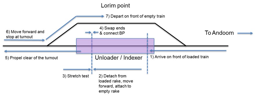
Section 5.3 of the Rio Tinto Weipa Railway Operational Procedures Manual provided safety procedures to facilitate rail movements into and out of Lorim Point. Section 5.3.4.2 specified the procedures for the driver when coupling the locomotive to an empty train. The procedure involved a trained competent person as well as the driver, and has been described diagrammatically in Figure 9.
Figure 9: Schematic of Lorim Point shunting movements
Source: ATSB
The procedure required that, after uncoupling from the loaded rake (Figure 9, step 2), the driver moved the locomotive to couple it to the empty rake. Following this, they tested that the coupling was secure by performing a stretch test and then the driver (Figure 9, step 3):
- Fully applies the Locomotive Independent Brake
- Open the Field Generator switch
- Centre the Reverser
- Signals the Competent Person that it is safe to enter the Rake to couple the Brake Pipe by indicating with the Thumbs Up signal.
The competent person then:
- Obtains a Thumbs up signal from the Driver that it is safe to go between the Rake and locomotive to couple up the Brake Pipe hose
- Uncouples the Brake-pipe Hoses from the Dummy Couplers
- Couples the Brake-pipe Hoses together
- Opens the Brake-pipe Isolating Cock on the Locomotive
- Slowly opens the Brake-pipe Isolating Cock on the Wagon so that a penalty Brake-pipe application does not result
- Presses the TRANSIT button, located on the corner of the Compressor Wagon
- Holds for 3 seconds and ensures that the READY FOR TRANSIT light comes on
- Moves clear and signals to the Driver using the Thumbs up signal that all is clear to proceed with any necessary Brake tests.
Finally, the driver:
- Follows all directions and signals from the Competent Person
- Provides the necessary signals and information in return to the Competent Person
- Changes end on the Locomotive [Figure 9, step 4]
- Performs a Brake-pipe [BP] Continuity Test as per Section 5.6.5. Brake Tests. This will ensure that the air system has no blockages and tests that a brake application can be successfully applied to all operational Wagons throughout the Train. The brake test is to be performed every time a Locomotive couples to a Rake. (If telemetry fails a manual continuity brake test must be performed)
- Push the Train back clear of 13 Switch [Figure 9, step 5].
Both the driver and fixed plant crew leader recalled largely following the procedure.
The ATSB’s review of the operator’s procedures was unable to identify a specific process for ensuring that, as part of the railway supervisor’s accountabilities, that a competent person was scheduled to be present at Lorim Point to assist the driver with the coupling process.
Brake tests
Section 5.6.5 Brake Tests provided information on the types of brake tests and when they needed to be performed. They were:
Terminal test
This test is performed to ensure that there is a continuous flow of air along the Brake pipe from front to rear, and also to ensure that the integrity of the Rollingstock is compliant following a period where the Rollingstock has not be used for more than 12 hours. It should be performed:
- After shut-down days or following major maintenance work on a Rake.
- On Flatcars at the commencement of a Machinery Move.
- When the number of Wagons attached during a Shunting operation exceeds One Third of the total number of Wagons on the Train.
Leakage test
This test is performed to monitor the rate of Leakage of Brake pipe pressure throughout the Train. It should be performed:
- During a Terminal test.
- On each Rake every 12 hours. The normal procedure is to test the first three Rakes of every shift. Thereafter, the Brake pipe leakage status of every Rake should be monitored as convenience allows and during any delays that may occur.
Continuity test
This test is performed to ensure that there is a Continuous flow of air along the Brake pipe from the front to rear of the Train. It should be performed:
- Each time a Locomotive is attached to either end of a Rake of Wagons or Flatcars.
- When the Locomotive has been detached and reattached to the other end of the Train.
- When the Shunting movement involves more than half the number of vehicles in the Train Rake.
- When any changes from ‘AUTO’ to ‘MANUAL’ are made to the wagon Telemetry system a “MANUAL” continuity brake test is to be performed.
Modified test
This test is performed to ensure that Brake pipe continuity still exists following a Shunting movement where the continuity of the Brake pipe has been interrupted. It should be performed:
- Each time the continuity of the Brake pipe has been interrupted during a Shunting movement unless:
- The Shunting movement involves more than half the number of vehicles in the Train Rake.
- The Locomotive has been attached to a new Rake of Wagons.
- The Locomotive has been detached and reattached to the other end of the Train.
- When the number of wagons attached during a Shunting operation exceeds one Third of the total number of wagons on the train.
Based on the driver’s interview, and associated paperwork, the terminal test and leakage test was performed prior to the accident trip.
There was no requirement in the Rio Tinto Weipa Railway Operational Procedures Manual to conduct a running brake test, that is, to perform a test on a moving train to ascertain that the brakes were operational.
Continuity testing
Continuity of the brake pipe from the locomotive through to the last wagon was normally conducted using a telemetry system. This system monitored the pressure in the brake pipe at the last wagon and displayed it to the driver in the locomotive cabin. In the event of any end of train telemetry issues (refer to section titled Brake and control systems), the telemetry systems could not be used to perform pre‑departure continuity tests remotely by the driver in the locomotive cabin. Instead, a manual procedure was available as outlined in Section 5.6.5.4 Continuity Test. The manual procedure required a competent person to assist the driver, as detailed below:
If the Telemetry system is not functioning or the wagon on the end of the Rake pressure readings are not giving the Driver the indications above, the Continuity test will be carried out manually in the following manner after the Override Switch has been placed from Auto Mode to Manual Mode:
- Competent Person asks for permission to enter the rear of the rake, then connects the hand held test gauge to the end of the Rake brake pipe hose, slowly opens the Brake Pipe cock, asks the Driver if the brake system is fully charged, and compares the pressure reading with the Driver, and then requests the Driver to make a 100kPa Brake pipe reduction.
- The Driver make’s a 100kPa reduction by advancing the Auto brake handle and watching the Equalising Reservoir gauge. An indication that the Brake pipe has stabilised is when both Equalising Reservoir and Brake Pipe pressure gauges are reading within +/- 5kPa of each other.
Note: If the Equalising Reservoir and Brake Pipe pressure keep reducing, ensure that the wagon Telemetry is not in Dump or Load mode.
- Competent Person checks that pressure has reduced by 100kPa and the brakes have fully applied to the last two wagons and compares the air pressure reading with the Driver.
- Driver releases the brakes.
- The Driver will check that the Flow meter indicates a flow of air to the brake system.
- Competent Person checks that the brakes have released on the last two wagons and that the Brake pipe pressure has returned to at least 550 Kpa and relays the air pressure reading to the Locomotive Driver.
- Competent Person closes the Brake Pipe cock, removes the hand held test gauge, places the air hose in the dummy and informs the Driver when clear of the Rake.
At interview, the accident driver indicated that no one ‘walks the train’ for the continuity test. The Rio Tinto investigation established that the continuity test conducted at Lorim Point was not completed in accordance with the procedure described above. The pressure check on the last wagon had not been completed and the flow meter was not checked. Reportedly, the driver had been shown how to complete the continuity tests by another driver and been applying this process for some time. The investigation concluded that there was an inconsistent understanding and application of the continuity test among the drivers. More than 6 months prior to the accident, the coupling and uncoupling process had changed to a predominantly single person process. However, the drivers had adopted an alternative process, which the drivers believed was an effective test.
Organisational information
Operator oversight
RTA Weipa Pty Ltd was exempt from accreditation under the Transport (Rail Safety) Act 2010, Queensland, as a low-risk railway. Low-risk railways were defined as being ‘a railway that is not connected to or associated with railway tracks of any other rail infrastructure of another railway or connected or associated with a rail or public road crossing’. On 1 July 2017, the Office of National Rail Safety Regulation became the rail regulator for Queensland. RTA Weipa Pty Ltd operated under a transitional arrangement until 22 May 2020, when they became accredited[17] under the Rail Safety National Law.
Audit and compliance activities
RTA Weipa Pty Ltd had an integrated health, safety and environment management system, which applied to all operational activities at Weipa. This system incorporated the rail safety management system, the Performance Assessment and Auditing Standard, and Critical Risk Management [CRM] Procedure, covering monitoring and audit.
The Performance Assessment and Auditing Standard outlined performance of the operations and was measured in several ways such as audits, interactions, inspections, recording incidents, and preventative, corrective and improvement actions. Audit and inspection requirements to measure compliance and conformance were also described in the standard. All audits conducted at Weipa and their findings were documented and remedial actions planned and implemented. Completion of actions was tracked in the HSE business solution and in the results of the Weipa’s conformance audits.
The CRM system, introduced in late 2015, identified the main risks in rail operations as rail collisions and rail impact on persons. The CRM was a layered verification process focussed on fatality elimination. The CRM provided a means to verify that critical controls were well designed, understood, in place and working at the front line, including controls described in the Rail Operations Manual.
The operator provided the ATSB with CRM verification records of audits conducted. A review of the records, for 2 years prior to the accident, showed regular audits being conducted addressing the ‘rail collision’ risk of the CRM. Of note is audit comments on 12 July 2019 and 12 December 2018. Both audits commented on procedures for shunting and continuity testing during every rake change in accordance with the railway operations manual. No non-compliance comments were recorded regarding shunting and continuity testing in accordance with the railway operations manual. However, shortly after the accident, Rio Tinto made the following comment with respect to securing rolling stock:
…Communicated with train drivers at shift start prohibition notice and requirement to perform brake continuity test as per operating manual for every rake change.
In addition to the above, the operator indicated that they conducted business conformance audits every 2 years, which was a second party assurance process. This generally involved the audit team attending the site (Weipa), reviewing procedures and records, and interviewing key personnel. An audit report was subsequently provided to the site and any findings were reviewed, with appropriate action taken. The details were then entered into the business solution. These audits had been completed at Weipa prior to the accident in 2016 and 2018.
Change management process
The Rail Industry Safety and Standards Board Railway operations – Management of change (AS 7472:2018) safety standard ‘describes the requirements to be applied by all rail organisations to ensure that safety risks associated with changes to railway operations, assets, or systems are identified and eliminated or reduced so far as is reasonably practicable’. Essentially, change includes anything that has the potential to alter existing risks or introduce new hazards. Therefore, a systemic view of Rio Tinto’s management of change process should be adopted to ensure that the impact on the rail system can be systematically identified, assessed, and controlled.
Under the HSEMS, the Rio Tinto Management of Change [MOC] Standard, in place since 2008, was applicable to the Weipa operations including rail operations. The intent of this standard was to ensure that changes to plant, process, and people systems that may cause harm, damage or have an adverse effect, were appropriately managed. This applied to new installations and changes in processes. The standard detailed the procedural steps to be taken when a change occurred including, but not limited to:
- investigating the impacts of the change
- conducting a risk assessment
- authorising the change
- communicating with affected stakeholders
- implementation
- evaluating change outcomes
- documenting an implementation plan using the MOC planning sheet
- entering the change into the change recording system.
During this investigation, RTA Weipa Pty Ltd advised the ATSB that a MOC entry had been made in the change recording system in 2010 detailing the amended wagon telemetry system at both the dump and load stations. They also supplied documents showing the engineering change management process was undertaken for this. However, no MOC process records for either the inoperability of the new telemetry system in late 2017 or the automation of the Lorim Point dump station in mid-2018 was provided. The Rio Tinto investigation report had also identified that a MOC or associated risk assessment could not be found for when the uncoupling and coupling process had changed from a 2-person to a 1-person task with the automation of the station.
RTA Weipa Pty Ltd later provided the ATSB with a MOC planning form, dated 16 October 2019, for reinstating the telemetry system.
Survival aspects
Collision sequence
The collision sequence was determined from closed-circuit television footage at the Andoom loading station. Figure 10 shows the trajectory of the second last (2089 - red line) and third last (2002 - amber line) wagon of the stationary rake when it was struck by locomotive R1006. Outside the field of view (to the left) was the last wagon (2023) of the rake. This wagon split in half on impact with the locomotive, with a portion landing on the rake mover mechanism to the left and another large portion landing to the right of the locomotive. The second last wagon could be seen to override remnants of the last wagon and then ride up over the locomotive before coming down to the right on its side. It was pushed clear of the adjacent track by the third last wagon, which the locomotive came to rest against (Figure 11).
Figure 10: Footage of the collision sequence (composite of 1 second intervals travelling left to right)

Source: Rio Tinto Aluminium Weipa, modified by the ATSB
Figure 11: Aerial photograph of the wreckage
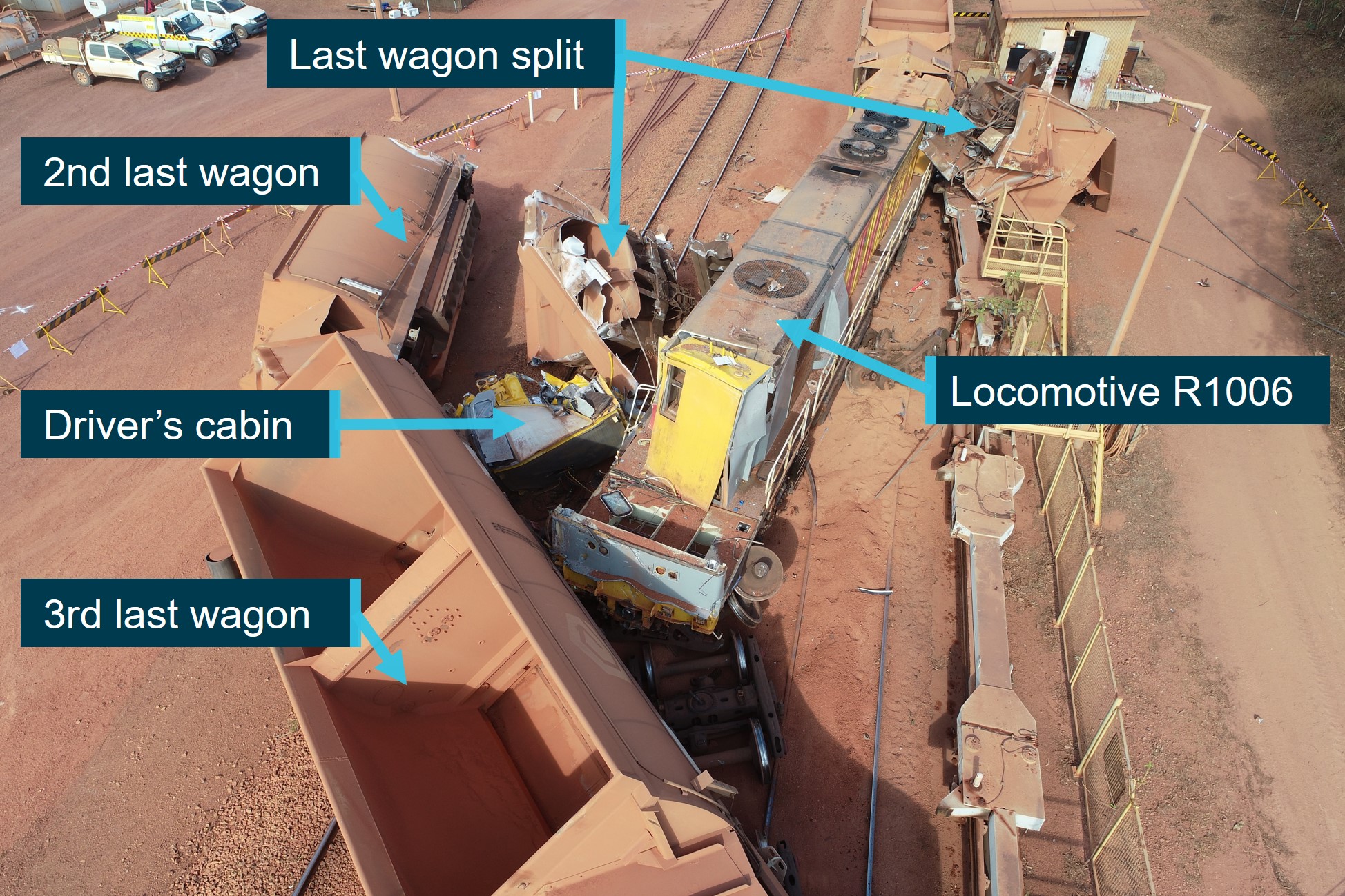
Source: Rio Tinto Aluminium Weipa, annotated by the ATSB
The coupler and frame of the locomotive took the majority of the initial impact forces. While the collision posts were struck as the locomotive under rode the trailing wagons, and withstood the impact with very little deformation, they were not effective at preventing the cabin from being crushed (Figure 12).
Figure 12: Locomotive collision posts
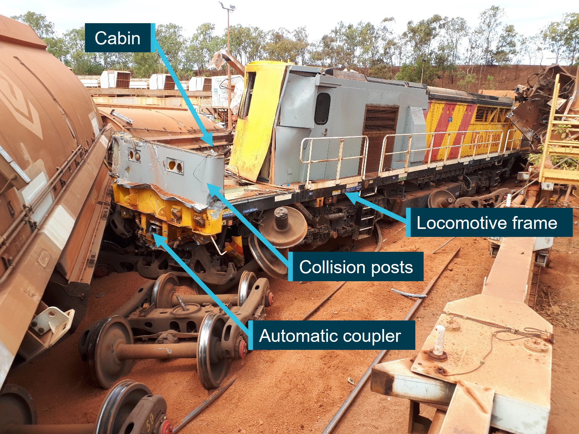
Source: Rio Tinto Aluminium Weipa, annotated by the ATSB
The driver’s cabin, which was a modular design (see Modular cabin crashworthiness below) became separated from the locomotive frame during the impact sequence. The cabin roof panel buckled under the compressive load of a wagon striking the windscreen area, and the horizontal roof panel folded back on itself. Further, it was also observed that, based on the folded direction of the panel to the rear of the side window aperture (Figure 13), a vertical compressive load had also been applied to the driver’s cabin at some point in the impact sequence.
Figure 13: Damage to the driver’s cabin
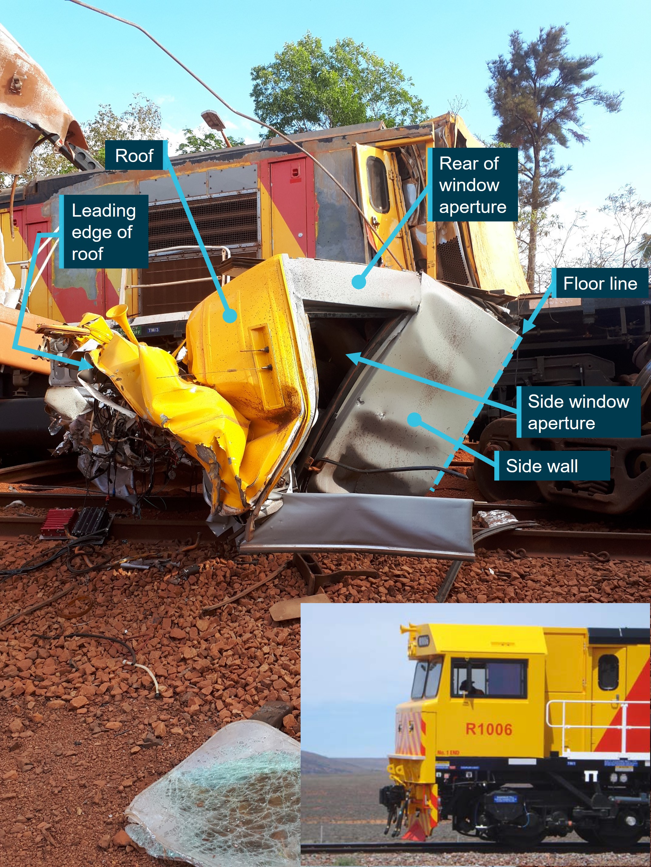
Source: Rio Tinto Aluminium Weipa, annotated by the ATSB
The vertical compressive load could have occurred due to an object coming down on the cabin or the cabin landing on its roof in the process of coming off the sub-floor structure. The damage sustained to the top right of the collision post near the modular cabin mounting point and the asymmetric compression of the services compartment immediately behind the cabin, suggests at least one wagon rode up over the collision posts
Modular cabin crashworthiness
Modular cabin mounting points
The 2 modular driver cabins in the JT42C locomotive (one at either end) had 4 isolating resilient mounting points (Figure 14) that connected the cabin to the superstructure of the locomotive. The rear mounting points were on each side underneath the floor approximately 250 mm from the rear of the modular cabin unit. The front mounting points were situated on each side midway up the front face of the cabin. These front mounts sat on top of the collision posts.
Figure 14: Position of the cabin isolating resilient mounts
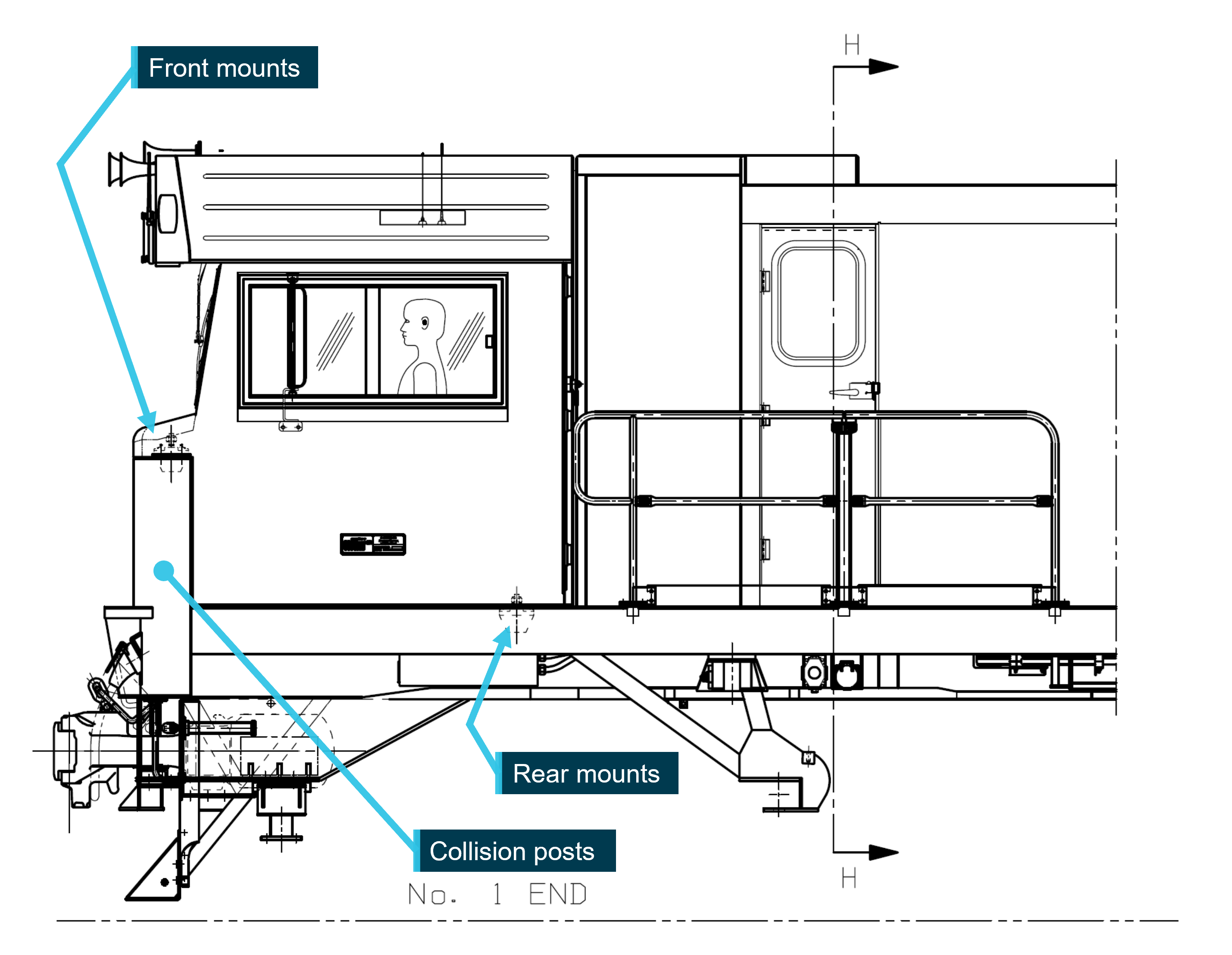
Source: Downer EDI Rail, annotated by the ATSB
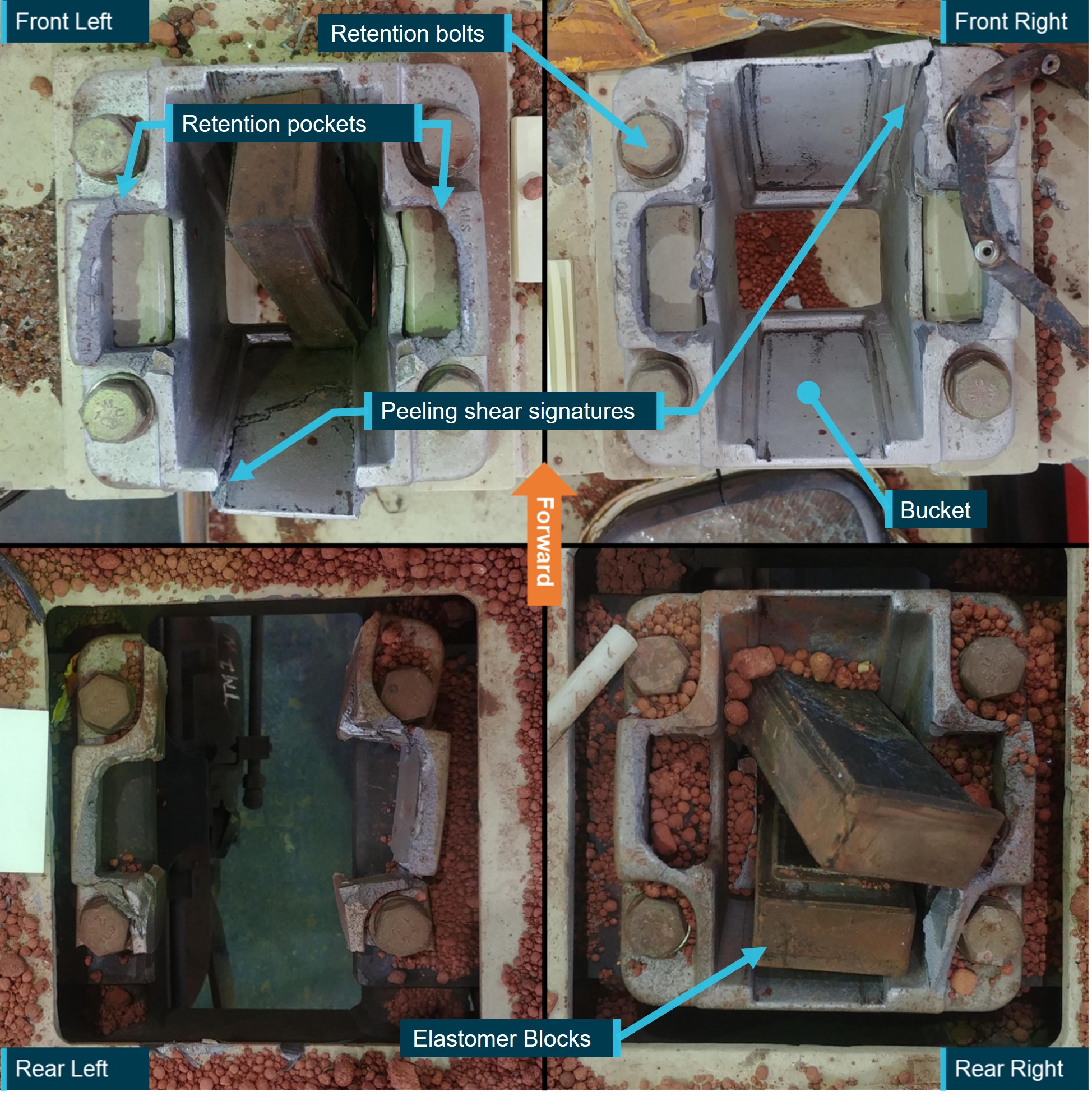
Each of the 4 mounts were a modular system of 2 elastomer blocks sandwiched between a cast iron wedge and aluminium outer casting with parallel angular faces (Figure 15). The wedge (and cabin) is held in the outer casting by gravity during normal operations and is designed to dampen vibrations through the elastomer blocks. When unloaded, or under a tensile load, the wedge is retained by 2 retention plates that bolt to the top of the wedge. The plates were slotted underneath a retention pocket feature in the outer casting. In normal operation, clearance was provided between the plates and pockets such that vibrations went through the elastomer blocks. The retention plates were only installed for the inverted (vertical up) load case.
Failure of the mounts
During the impact sequence, the front cabin mounts failed first under impact overload conditions. This allowed the cabin to fold back into the locomotive structure behind, resulting in the rear mounts also failing and the cabin separating from the locomotive structure.
In all cases, the wedge remained intact and the outer casting portion failed (Figure 15). Both front outer castings had peeling shear signatures from horizontal pressures applied by the wedge and elastomeric blocks. Markings on the rear right casting indicated the wedge departed to the right. The rear left outer casting disintegrated and had marks indicating the wedge may have departed with a large angle of rotation.
Figure 15: Cabin isolating resilient mounts
Source: Rio Tinto Aluminium Weipa, annotated by the ATSB
A feature common to both sides of all 4 aluminium outer castings was the failure of the top face of the retention pocket. This indicated that a substantial upwards load had been applied to each mounting point. All failures were symptomatic of a brittle material failing in overload. The failure force had been applied by the retention plates installed on the top of the wedge. The state of the retention plates after the accident varied widely. While some were bent and others were not, some were missing entirely due to their attachment bolts failing. However, there was evidence that some retention plates may have deformed or failed after the cabin had separated from the locomotive structure. In at least one case, a retention plate was bent upwards, which could not occur with the wedge positioned in the outer casting.
Collision standards
RTA Weipa Pty Ltd locomotives
In 2007, RTA Weipa Pty Ltd commenced a locomotive replacement program. As part of this process, a technical specification was developed, which specified the minimum requirements for the design of the locomotive to operate on the RTA Weipa Pty Ltd network.
During the procurement process, RTA Weipa Pty Ltd specified within the contract that the locomotive must meet the relevant standards as follows:
4.0 Codes and Standards
The locomotive shall be designed and manufactured in accordance with the appropriate:
- Australian Standards
- British standards where Australian standards are not available
- Association of American Railroads standards
- Federal Railroad Administration of America
- International standards applicable to rotating and semiconductor electrical machines,
- Railways of Australia Manual 1992 for standard gauge interstate freight and passenger stock.
It was noted that specific references, revision status, or hierarchy of the required standards were not detailed.
The Downer EDI Rail Engineering Report CER01061 – LM10 Locomotive Compliance Plan stated that the collision protection system complied with a 1994 version of an Association of American Railroads standard AAR S-580. At the time of the locomotive’s construction, the 2005 revision was current. The reason for the choice of AAR S-580 revision was not determined.
The technical specifications[18] required ‘Where an isolated cabin is fitted the supplier shall provide full details of the separation protection system in the event of collision with other rolling stock’. The compliance plan only referred to S-580 and stated the cabin sat behind the collision posts. It did not address the specification’s requirement to resist separation other than routine operational cabin retention.
The manufacture of these locomotives predated the rail co-regulatory framework by which Australian rail, including the manufacture of rolling stock, is now governed. However, the locomotives were based on an existing design,[19] circa 1997, which would have met the above standards. This was potentially the reason for the JT42C locomotive being designed to a 1994 crashworthiness standard.
For this JT42C locomotive, the Railways of Australia manual 1992 appeared to have been the primary design standard as it was cited in the Downer EDI compliance plan as part of the locomotive replacement contract. While the standard did not refer to modular cabins, the loads and loading criteria requirements were all encompassing in their application. Therefore, it appeared the design requirements for the locomotive modular cabin had been 4g longitudinally, and 2g laterally and vertically. The similar GT42CU-AC locomotive design (involved in the Ambrose derailment discussed in Similar occurrences) calculations used a ‘Vertical acceleration of 2g plus static load’.
It was noted that, given the unseating of a cabin is more likely to result from an impact with another vehicle rather than from inertia, defining a force for collision protection systems and loading criteria could be more suitable than an acceleration.
Survivable space
Crashworthiness standards are intended to preserve life using methods that limit the loads experienced by occupants through restraint and retention of occupants. A key aspect of this is to ensure that the space provided for occupants is not crushed, is free from harmful objects (such as loose or sharp objects) or otherwise become dangerous (for example, debris ingress). A space designed to perform in this manner may be considered a ‘survivable space’. This can be achieved through design and/or performance criteria.
In the Australian context, survivable space was discussed during the investigation into the level crossing collision between the Cairns tilt train (CTT) and a loaded B-Double truck at a level crossing at Rungoo, Queensland on 27 November 2008 (Queensland Transport report QT2459). The 2 train drivers were fatally injured and the truck driver sustained moderate injuries. In addition, 9 passengers were injured. The investigation findings noted:
26. The driver’s cabin of the Cairns Tilt Train lozenged during the collision sequence thereby reducing the amount of survivable space within the driver’s cabin.
27. Australian and international rollingstock standards do not take into account high levels of lateral loading in their crashworthiness requirements.
33. It was unlikely that a train driver’s cabin built to a modern crashworthy standard, if subjected to the forces involved in the collision at Rungoo, would have resulted in significantly greater survivable space.
The Queensland Coroner’s findings into the collision at the Rungoo level crossing also highlighted the importance of survivable space to preserve life:
The front of the CTT impacted the leading trailer of the B-double truck about eight metres from the truck’s front bull-bar. The angle of the collision and the speed and weight of the B-double truck imparted very high lateral forces on the driver’s cabin of the CTT. This caused the driver’s cabin to lozenge which, in turn, reduced the amount of survivable space afforded to the train’s two drivers. In essence, the lead power car and, in particular, the driver’s cabin of the CTT, bore the brunt of the force of the collision. This was evidenced by the fact that the power car was rotated about 135 degrees in an anti-clockwise direction and that the driver’s cabin sheared to the left while the rest of the train’s nine carriages remained relatively undamaged.
Crashworthiness of the Drivers’ Cabin
The drivers’ cabin of the Tilt Train lozenged during the collision sequence reducing the amount of survivable space. The Rail Safety Investigation found that the Tilt Train was constructed in accordance with the QR crashworthiness requirements of the applicable standard from 1999. That standard was consistent with European and American Standards for crashworthiness at the time. However, these rolling stock standards do not take into account high levels of lateral loading in their crashworthiness requirements. Further, not all of the aspirational specifications contained in the standard were fully confirmed as being incorporated in the design of the Tilt Train drivers’ cabin. Even if the Tilt Train driver’s cabin had been fully compliant with all the aspirational requirements, the survivable space would not have been significantly greater. Further, it is unlikely drivers’ cabin built to a modern crash standard, if subjected to the forces involved in this collision, would have resulted in significantly greater survivable space.
Although the CTT investigation focussed on reduced survivable space due to lateral loads, the same observations can be made in relation to the accident at Andoom involving longitudinal and vertical loads, the engineered protection provided by the collision post, and movement of the modular cabin away from that protection. In the context of this investigation, Figure 16 illustrates the potential survivable space of a modular cabin that has separated (left) versus remained fixed behind the collision posts (right).
Figure 16: Locomotive cabin survivable space
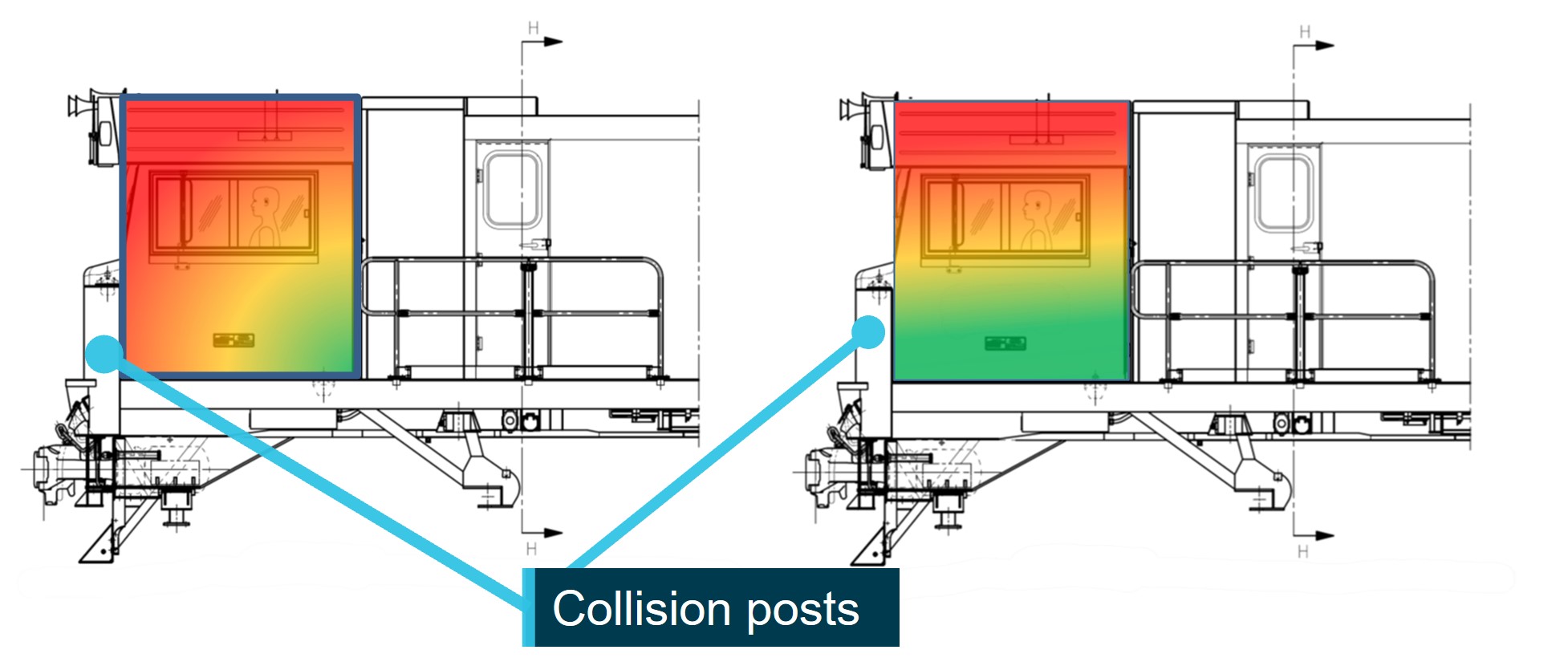
Note: Green represents a higher probability of survival, red represents a lower probability of survival.
Source: ATSB
Australian crashworthiness standards at the time of the collision
The rail industry in Australia uses the Australia Standards, administered by the Rail Industry Safety and Standards Board (RISSB), to benchmark design and performance standards for the rail industry. As part of the RISSB suite of standards, the following applied to new locomotive crashworthiness at the time of the accident, but not at the time of build of R1006 (JT42C):
- AS 7520.1 – Australian Railway Rolling Stock – Body Structural Requirements Part 1 – Locomotive
- AS 7521 – Interior Crashworthiness
- AS 7533.1 – Australian Railway Rollingstock – Driving Cabs – locomotives.
AS 7520.1-2012 required rolling stock to meet load requirements for horizontal and vertical components of compressive loads, tensile loads, anti-climb devices and collision posts (referring to Association of American Railroads (AAR) S-580:2008 for the latter). The standard also required a crash energy management system.
AS 7520.1-2012 also required rollover protection. This included assessments of the structures of the locomotive for inverted and sideways load scenarios. Although they were static scenarios and only needed to support half and the whole weight of the vehicle with the vehicle at rest. It did not consider the loads involved in arresting the vehicle during a rollover event or impact. The cabin roof also required a penetration test, which equated to 3,000 joules. However, it did not consider the cabin separating from the locomotive structure.
Further, body mounted equipment was required to meet ‘shock/minor impact loading’. It was unclear whether a modular cabin would be considered ‘body mounted equipment’. However, the inertia requirements were the same as applied to equipment in the Railways of Australia manual 1992 (section 13.7.1.2 for fixtures and cabin structure/penetration) and as applied during the mounting system check after the Ambrose accident (refer to section titled Similar occurrences).
In the event of a collision between 2 trains, a considerable amount of energy must be dissipated. One of the potential consequences of such a collision is override of one of the leading vehicles onto the other. Due to their high longitudinal strength and stiffness, locomotives are particularly susceptible to underride when they collide with another vehicle. This often results in significant consequences to the occupants of the under-riding vehicle.
At the time of accident, there was no Australian standard that specifically covered the crashworthiness of locomotive modular resilience and retention. Notwithstanding this, the JT42C (R1006) locomotive design pre-dated the above standards and met the current Australian standards.
Similar occurrences
The ATSB conducted research into other occurrences where modular cabin mounts had failed. Four accidents were found, detailed below.
Ambrose
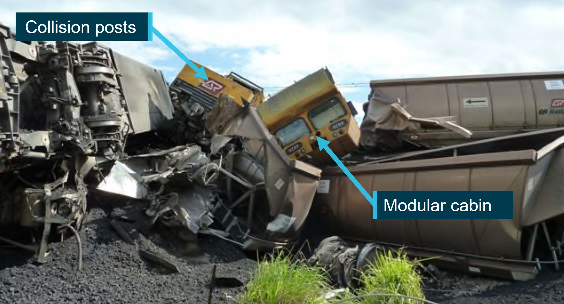
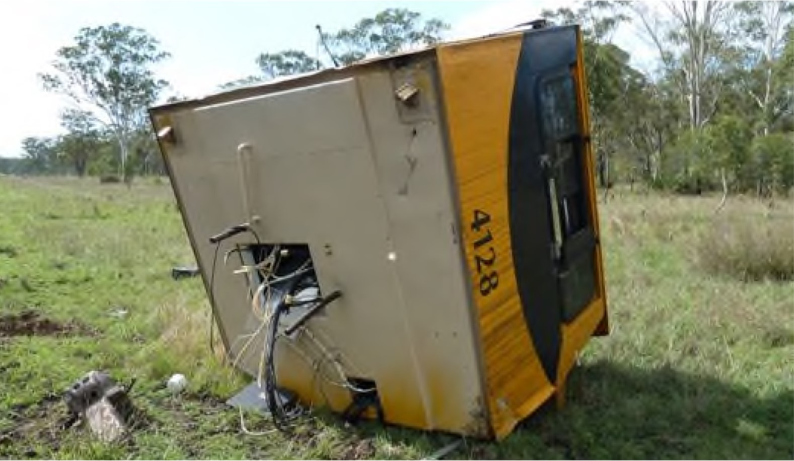
On 8 February 2013, a coal train derailed near Ambrose, Queensland. The coal train consisted of 100 wagons hauled by 4 locomotives, 2 at the head end and 2 mid-set operating under distributed power. Approximately 12 wagons ahead of the remote locomotives derailed. These wagons and the 2 remote locomotives (4020 and 4128) jack-knifed and derailed. The driver’s cabins on both these locomotives separated from the main structure (Figure 17 and Figure 18).
Following the derailment, multiple internal reports were conducted by the operator (Queensland Rail) and the manufacturers (Downer EDI and ElectroMotive).
Figure 17: Locomotive 4020 and disconnected cabin
Source: ElectroMotive Engineering Report
Figure 18: Locomotive 4128 driver’s cabin
Source: ElectroMotive Engineering Report
The modular cabin design compliance with Railways of Australia manual 1992 had been conducted by Downer following the Ambrose derailment. The Ambrose vehicles were GT42CU‑AC locomotives, however, the style of modular cabin mounts and positions were the same as the JT42C locomotives. The supplier of the mounts performed tests to check the overload capacity of the mounts. When compared with the specifications for the mounts, the ATSB’s analysis of the test results found that the cabin mount system had, for the worst-case scenario, a 10% margin of safety on the design requirements and 75% margin of safety on the tested strength of the fittings.
It was assumed that the mass of the GT42CU-AC and JT42C locomotive cabins were similar, and considered acceptable to the JT42C given the nature of the simple static force assessment.
Both the Downer EDI and ElectroMotive reports made recommendations that the cabin mounts be strengthened. The Downer report additionally stated, ‘It is highly undesirable that the cabin should separate from the locomotive, even under overload conditions’. The Downer EDI report discussed a modification to the design that claimed a fourfold increase in strength.
Downer EDI did not implement the new cabin mount design following this recommendation as the locomotive design was transitioning to a new owner, Progress Rail. However, upon enquiries by the ATSB, Progress Rail conducted their own review and initiated a different design change.
Bureau of Air Safety Investigation (1998/001)
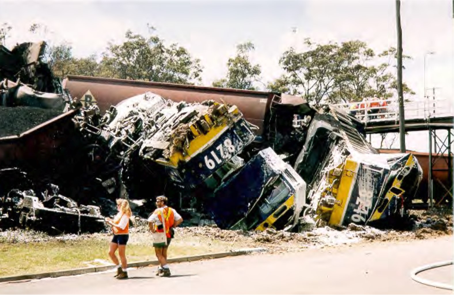
On 23 October 1997, a loaded coal train struck the rear of a stationary coal train at Beresfield, New South Wales. A total of 3 locomotives and 13 coal wagons were derailed and destroyed. The second locomotive (8219) ended inverted with the driver’s cabin disconnecting from the main structure (Figure 19). It was not occupied at the time. A New South Wales Department of Transport independent inquiry was conducted by the Bureau of Air Safety Investigation (BASI).
Figure 19: Locomotive 8219 inverted with cabin disconnected
Source: Bureau of Air Safety Investigation
ATSB investigation (RO-2011-016)
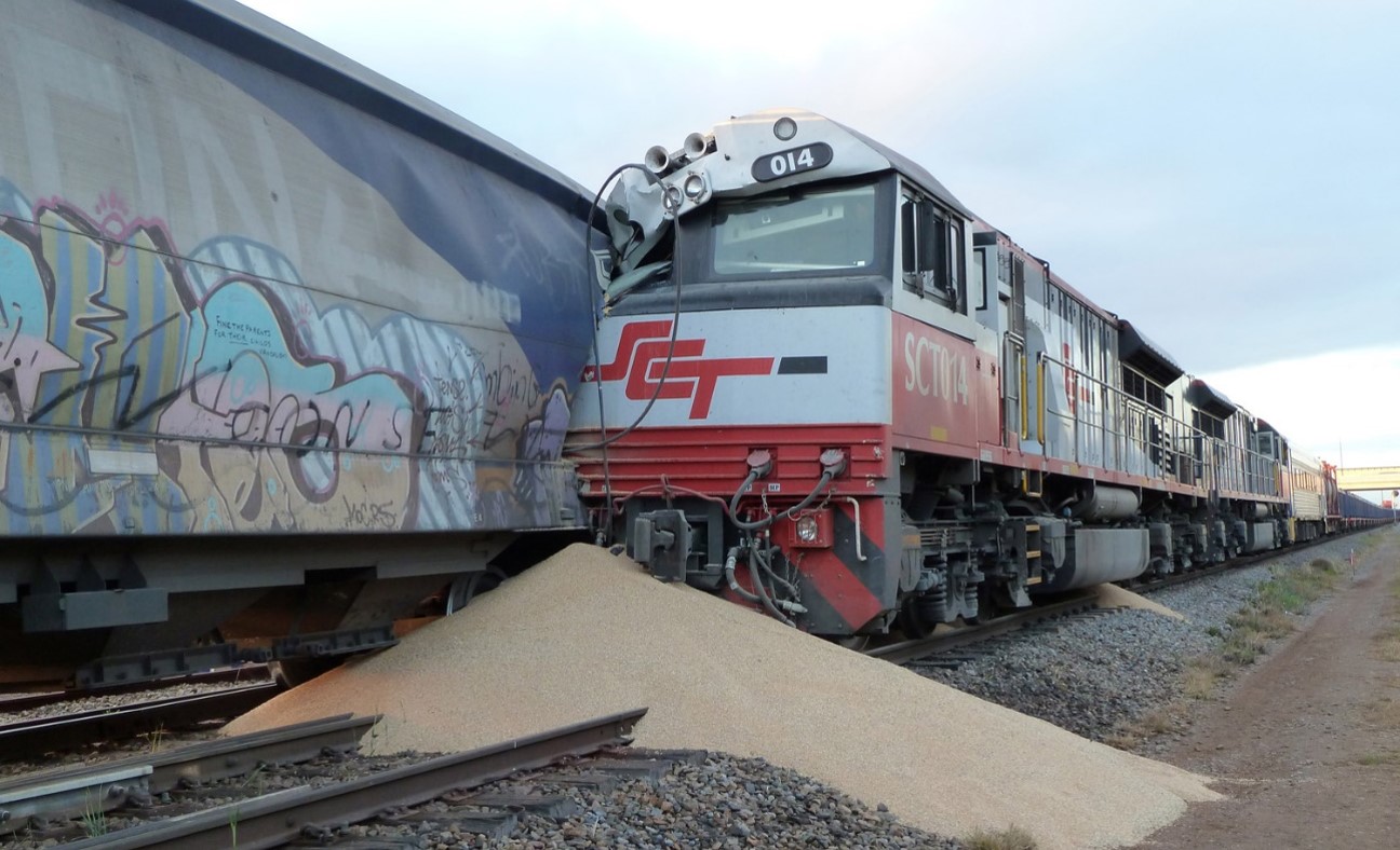
On 11 October 2011, an empty ore train struck loaded grain wagons traversing a turnout at Dry Creek, South Australia. The lead locomotive obliquely struck the wagons impacting the top right corner of the modular drivers’ cabin (Figure 20).
Figure 20: Locomotive SCT014 with collapsed right side of cabin
Source: ATSB
The ATSB investigation found that the front right mount (on top of the collision post) failed due to direct contact with the grain wagons. While there was gross intrusion into right side of the cabin, the survivable space was maintained as the cabin structure remained in place behind the collision posts.
National Transportation Safety Board (NTSB/RAR-12/02)
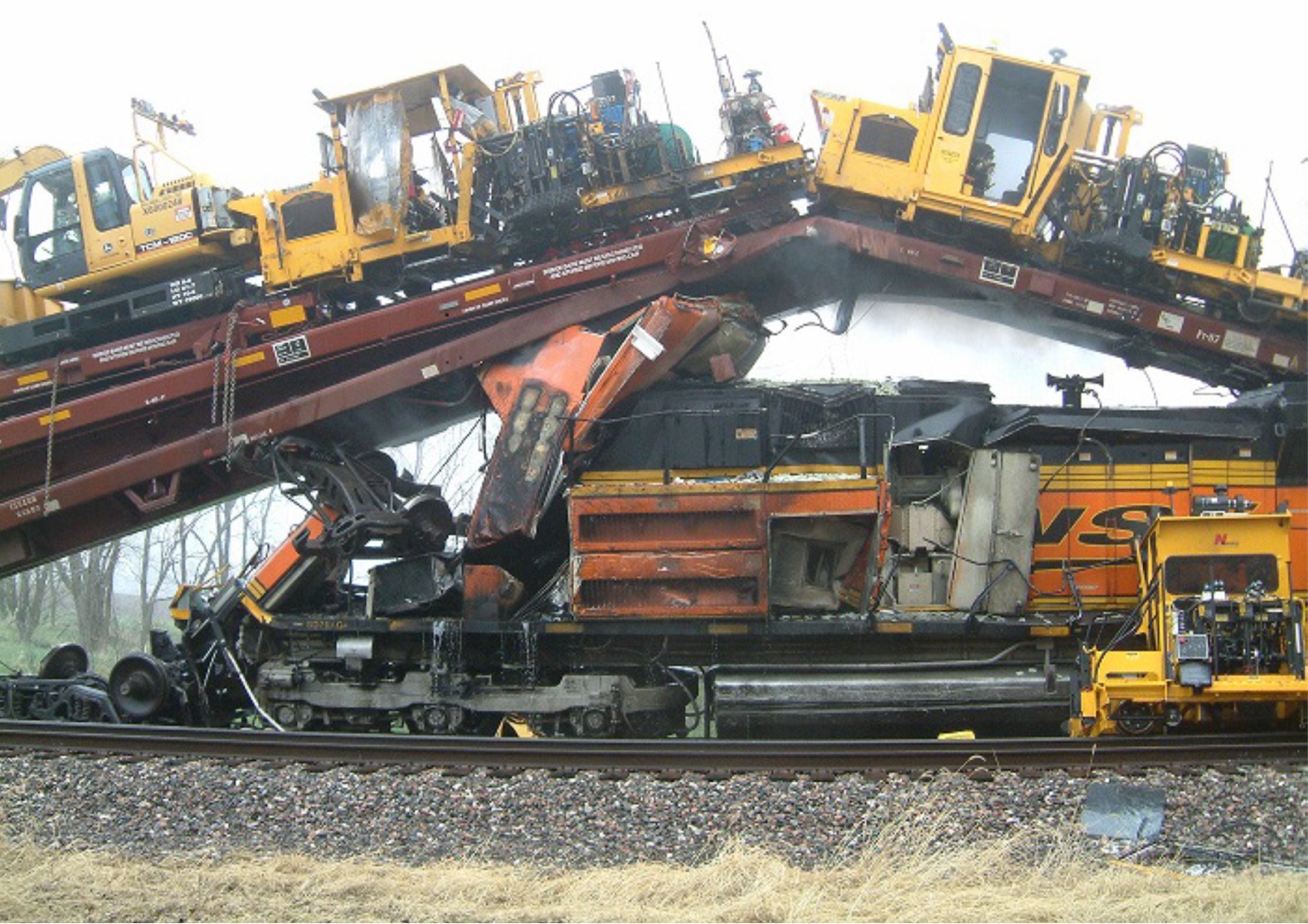
On 17 April 2011, a coal train collided with a stationary maintenance-of-way equipment train at Red Oak, Iowa, United States. This resulted in the last 4 cars of the equipment train riding up and over the coal train locomotive. The last car caught the windscreen and roof pulling it up and rearwards, detaching the front mounts of the modular cabin and crushing it against the structure behind. Both crewmembers on the striking coal train were fatally injured.
The modular cabin had sustained a substantial loss of occupied space. The cabin had separated from the locomotive and the bottom half of the cabin rotated up just over 90°. The roof and left rear corner of the cabin were crushed. The side walls remained intact to the point of the window line and the underside was relatively intact. The general condition of the modular cabin attachment points indicated that they had been subjected to severe vertical forces and shear. When the cabin separated, the short hood and collision posts no longer provided the protection intended by the crashworthiness design standards. It was noted in this impact that the collision posts were bent back over 30° (Figure 21).
Figure 21: Locomotive over-ridden by equipment train
Source: National Transportation Safety Board
While the National Transportation Safety Board’s (NTSB) investigation emphasised that modular cabins were very effective at reducing crew noise and vibration exposure, there were no crashworthiness criteria for these type of cabins in the existing standards. They concluded that the current standards included a procedure to validate alternative locomotive crashworthiness designs, but this was not effective in identifying modular cabins as an alternative design. The NTSB indicated that the existing crashworthiness requirements were design standards rather than performance standards distinguished by:
Design standards fix requirements under prescribed conditions, which are not necessarily related to the variety of conditions that could occur in a collision. They were based on specific accident scenarios and on locomotive designs in use at the time of their development. In comparison, performance standards attempt to define equipment performance requirements. For example, maintaining survivable space in a control compartment following a collision is a performance standard; prescribing the strength of a collision post in front of the control compartment is a design standard.
Therefore, the NTSB recommended that the Federal Railroad Administration (FRA) (R-12-21) and Association of American Railroads (R-12-23) amend the relevant regulations and standards to ensure the protection of occupants of modular cabins in the event of a collision. They also recommended the FRA require crashworthiness performance validation for all new locomotive designs (R-12-22).
The FRA responded that they had published a final rule that had fulfilled the intent of the recommendations. The NTSB did not agree with this, noting the ruling had been published before the recommendations were issued. On that basis, the NTSB closed the FRA recommendation as unacceptable. The Association of American Railroads had made some changes to the standards, but the recommendation remained open as the revisions did not apply to all locomotives nor did it define modular cabins or subfloor.
Safety analysis
Introduction
When approaching the Andoom loading station, near Weipa, Queensland, the driver applied various braking configurations, but the train did not slow. Consequently, when travelling at about 37 km/h, the empty ore train collided with a partially loaded rake of wagons at the loading station. This resulted in the locomotive and 4 empty wagons derailing on impact. The collision also resulted in the leading end modular driver’s operating cabin being crushed and separating from the main structure of the locomotive, coming to rest on the ground.
This analysis will discuss the actions and processes applied, and required, to ensure continuity of the train’s braking system. It will also consider the design and crashworthiness requirements of modular driver cabins.
The connection
After the accident, the pneumatic brake pipe cock was found to be open on the locomotive but closed on the wagon directly behind the locomotive. This configuration would have prevented continuity of air through the train’s brake pipe from the locomotive to the wagons.
The brake pipe was last connected at Lorim Point when the locomotive was connected to a rake of empty wagons by the driver assisted by the fixed plant crew leader. Following the brake pipe connection, recorded data showed that there was a small airflow during brake pipe recharging, similar to when the brake pipe was recharged before the connection. This differed from what was detected on the earlier trips and indicated that the brake pipe volume remained small, and that brake pipe air was not flowing to the wagons. This is consistent with the pneumatic brake pipe cock not being opened as observed after the accident.
Therefore, it was almost certain that during coupling operations at the Lorim Point dump station, the fixed plant crew leader inadvertently did not open the pneumatic brake pipe cock on the first wagon. This resulted in the wagon brakes not operating when commanded by the driver on approaching Andoom, leaving only the locomotive brakes functional.
Pre-departure checks
The continuity brake test was a preventative control to check there was a continual flow of air along the brake pipe from the front to rear of the train before movement, indicating the system was correctly connected. As the telemetry system was not available, this process was done manually with a second person assisting the driver. Indications that the pipe was not correctly connected could be detected by the second person observing that the brakes on the wagons did not apply, and/or by the driver observing that there was not a normal (large) air flow when the brake pipe was recharged.
However, the recorded data showed that, for the accident trip, a 100 kPa brake pipe reduction was not observed after connection. The only change was a reduction from 600 to 400 kPa but this was either coincident with, or prior to the brake pipe connection. Therefore, based on the recollections of the driver and fixed plant crew leader at interview, along with recorded data timings, the brake continuity test was not performed during the pre-departure check (after brake pipe connection) despite being required in the coupling procedure. The brake continuity test was an opportunity to detect, diagnose, and correct the omission to open the brake pipe cock on the first wagon. Pre-departure checks are critical to ensuring the integrity of the train and braking system.
Further, during the push-back of the empty rake to behind the number 13 points, the train did not respond as expected. The recorded data showed significantly less braking was required by the driver when arriving at Lorim Point with a loaded train when compared with that required for pushing the empty rake back to the number 13 points. The driver had used a near full-service application of the automatic brake and a significant amount of independent brake in order to stop the empty train after the propelling move. However, the driver dismissed this as an auxiliary compressor and continued the journey towards Andoom. This was another missed opportunity, through checking gauges, to correct the brake pipe cock omission before starting the journey.
The collision
Due to the railway alignment, topography, and train handling, there was no requirement for the driver to use the train brake during the journey until reaching the Andoom arrival braking point. When approaching the loading point at a location consistent with previous trips, the driver applied the train brake when at 64 km/h. However, the train did not respond as expected.
Consistent with the recorded data, the driver reported attempting to slow the train using different braking configurations, including the emergency brake. However, the train only decelerated to 37 km/h before colliding with the rear of a stationary ore train.
Inconsistent application of procedures
As the telemetry system had not been operating since late 2017, the manual technique for conducting the brake continuity test as part of the coupling process, as stipulated in the operator’s procedures manual, was to be followed. This procedure required 2 people (the driver and a competent person) to conduct the process. However, with the automation of the Lorim Point dump station, a qualified plant operator was no longer routinely available at the station to assist with this process. The accident driver reported that the coupling process was completed by the driver primarily unassisted. This was consistent with the operator’s investigation, which indicated that a second person infrequently assisted.
The ATSB’s analysis of the locomotive recorder data prior to the accident showed variations with the coupling process across the drivers. In particular, these related to the change of cabin, brake pipe connection, and brake continuity test processes. The accident driver had also indicated that no one would ‘walk the train’ for the continuity test, although the test required visual observation of the brakes being released and comparing the brake pipe pressures at the rear of the train with that shown in the driver’s cabin. Likewise, the operator had identified that the drivers had adopted an alternative process.
Procedures are designed to assist with reducing variation within a given process and ensure operations are performed correctly. The inconsistencies identified for the coupling process likely increased the risk of the omission of an action, an inappropriate action, or critical errors not being detected and corrected before departing. In this case, the pneumatic brake pipe cock not being opened on the first wagon, the pressure check on the last wagon not being completed, and the flow meter not being checked.
Auditing railway operations
RTA Weipa Pty Ltd was conducting regular workplace safety activities under the critical risk management system and had also conducted a business conformance audit leading up to the accident. This encompassed the period where the manual coupling process was being applied and the dump station was automated. The audits conducted included elements of rail operations such as shunting and the brake continuity testing.
The purpose of the critical risk management system audits was to verify that the critical controls put in place were well designed, were understood, and were working at the time. However, the audits did not identify, and therefore correct, the inconsistent application of the coupling process at Lorim Point, in particular, the manual brake continuity test.
Change management
The operator’s health, safety and environment management system, included a management of change standard, which detailed the process to be taken when new installations were introduced or changes to processes were made. The operator had demonstrated that this process had been previously used in 2010 and after the accident. However, there was no evidence to indicate that such a process had been applied when the newly installed telemetry system was deemed inoperable resulting in the pre-departure brake continuity test having to be performed manually. Likewise, when the Lorim Point dump station became automated, changing this test from a 2‑person to a 1‑person process. This was also identified by the operator as part of their internal investigation.
As emphasised by the Rail Industry Safety and Standards Board, management of change processes ensure that any impact on the rail system resulting from a change can be systematically identified, assessed, and controlled. In this case, not completing the process for these changes were missed opportunities to review the adequacy of the existing procedures and ensure that any potential safety risks were appropriately managed. This potentially influenced the drivers adopting an alternative brake continuity testing process.
Modular cabin crushed and separated
During the collision sequence, the modular cabin mount retention pockets failed due to material overload. This failure allowed the cabin to lift and fold back on itself, into the locomotive structure behind, and become separated from the locomotive frame. The failure, lift, and separation compromised the survivable space within the cabin, normally afforded by the collision posts. Although, in this instance, the driver was not seriously or fatally injured, the cabin was severely crushed. Cabin integrity during a collision is critical to survivability.
Survivability is associated with the preservation of survivable space within the cabin design. The more survivable space, the greater the survivability. In both the safety investigation and Coroner’s report into the tilt train accident at Rungoo, Queensland, on 27 November 2008, survivable space was featured and used as a measure of survivability. In addition, the United States National Transportation Safety Board investigation report into the accident at Red Oak, Iowa, links survivable space to increased survivability.
Modular cabin mount design
As discussed above, the frontal impact of the locomotive (type JT42C) with the last wagon on the stationary rake resulted in the front modular cabin isolating resilient mounts failing followed by the rear mounts. The ATSB’s photographic examination identified that the damage sustained to all 4 retention pockets indicated that a substantial upwards load had been applied to each mounting point during the impact sequence.
Similarly, the resilient mounts on the modular cabins in the Ambrose accident (locomotive type GT42CU‑AC) had also failed under impact forces. While these 2 accidents involved different locomotive types (but from the same manufacturer - Downer EDI), the style of modular cabin mounts and positions were the same. As a result of the Ambrose accident, it was recommended that the cabin mounts be strengthened noting that it was undesirable for the cabin to separate from the locomotive particularly during an impact.
These 2 accidents demonstrated that the modular cabin mounts were not resilient to frontal impact forces during a collision. As previously discussed, the collision posts provide protection for the survivable space in the event of such a collision. However, if the mounts fail and the cabin becomes separated from the locomotive structure, this protection is lost.
Crashworthiness standards
The use of modular locomotive cabins is not new. The JT42C locomotive was based on a pre‑existing design, which met the required Australian crashworthiness standards used by the rail industry, both at the time of manufacture and at the time of the accident. However, these standards did not provide specific design and/or performance requirements for locomotive modular cabin resilience and retention. Without clear design and/or performance measures, the rail industry used standards that best matched, such as the Railways of Australia 1992, section 13, fixtures and cabin structure/penetration standards.
Collision protection systems, including the collision posts, and the locomotive underframe provided adequate survivable space for cabin occupants. This protection was provided by design standards based on prescribed forces. While the introduction of modular cabins improved in-cabin vibration and noise issues, it created a disconnect between the collision posts and what they were designed to protect, survivable space.
In this accident, the collision posts and underbody structure remained intact and provided a volume suitable for survival space. Although the structure provided protection from the initial impact (in the lower half of the cabin), with the cabin separating from the locomotive, that protection was lost. The cabin was now vulnerable to the derailing wagons going over the top and to either side.
This was consistent with the Red Oak accident in the United States, where it was established that, once the cabin had separated, the short hood and collision posts no longer provided the protection intended by the crashworthiness design standards. The investigation into this accident had also concluded that the existing standards did not stipulate crashworthiness criteria for modular cabins. Consequently, recommendations were made for the inclusion of such criteria in the relevant regulations and standards to ensure the protection of the occupants in the event of a collision.
The absence of standards for modular cabin mount strength and retention created the risk that the survivable space could move from behind the protection of the collision posts. Without specific design and or performance standards for modular cabins, there was no baseline measure of safety for preservation of survivable cabin space during a collision.
Missing procedure
As previously discussed, the coupling process incorporating the brake continuity test required 2 people to complete as per the documented procedure. Since Lorim Point had become automated and a permanent plant operator was no longer positioned at the station, the railway supervisor was accountable for ensuring a second competent person was available to assist the driver with the coupling process. However, the ATSB was unable to identify a procedure to support this requirement.
Therefore, the availability of a second person was more informal. This was consistent with the accident driver and operator’s experience, where they indicated that a second was not always present to assist. Consequently, drivers had to adapt the 2-person task when required.
Standard operating procedures are a crucial risk control for ensuring day-to-day operations are performed consistently and correctly. This also ensures that all those involved in the process have a shared mental model of the task and their individual expectations are clear. In this case, without a formal procedure, there was no assurance that a competent person was always scheduled and available at the station for the coupling process.
Findings
|
ATSB investigation report findings focus on safety factors (that is, events and conditions that increase risk). Safety factors include ‘contributing factors’ and ‘other factors that increased risk’ (that is, factors that did not meet the definition of a contributing factor for this occurrence but were still considered important to include in the report for the purpose of increasing awareness and enhancing safety). In addition ‘other findings’ may be included to provide important information about topics other than safety factors. Safety issues are highlighted in bold to emphasise their importance. A safety issue is a safety factor that (a) can reasonably be regarded as having the potential to adversely affect the safety of future operations, and (b) is a characteristic of an organisation or a system, rather than a characteristic of a specific individual, or characteristic of an operating environment at a specific point in time. These findings should not be read as apportioning blame or liability to any particular organisation or individual. |
From the evidence available, the following findings are made with respect to the collision between two ore trains at Andoom, near Weipa, Queensland, 22 September 2019.
Contributing factors
- The pneumatic brake pipe cock was not opened between the locomotive and wagons during the coupling process, resulting in the wagon brakes not operating when commanded.
- The brake continuity test was not performed during the pre-departure check. This, combined with the greater than normal braking required on push back past the number 13 points, were missed opportunities to detect that the pneumatic brake pipe cock to the wagons had not been opened.
- When approaching the loading point at 64 km/h, the driver applied the train brake, however, the train did not respond as expected. The driver applied the emergency brake and the train decelerated to 37 km/h before colliding with the rear of a stationary ore train.
- The coupling process being used was inconsistent with the published procedure, including pre‑departure checks involving brake continuity testing. The inconsistencies likely increased the risk of the omission of an action, an inappropriate action, or critical errors not being detected and corrected before departing.
- Routine audits conducted by the operator on the Weipa operations did not identify the inconsistent application of the coupling process.
- Management of change processes were not conducted when the telemetry systems became inoperable and the Lorim Point dump station was automated. These were missed opportunities to review the adequacy of existing procedures to identify, eliminate or reduce potential safety risks associated with these changes.
Other factors that increased risk
- During the collision sequence, the modular cabin mount retention pockets failed due to material overload, allowing the cabin to fold back on itself into the locomotive structure behind, and become separated from the locomotive frame. This compromised the survivable space within the cabin afforded by the collision posts.
- The design of the modular cabin mount was not resilient to frontal impact forces in the event of a collision. This increased the risk of their failure and separation of the cabin, removing the effectiveness of protection afforded by the collision posts. (Safety issue)
- The Rail Industry Safety Standards Board did not provide design and/or performance standards on modular cabin resilience and retention for locomotive crashworthiness. (Safety issue)
- The RTA Weipa Pty Ltd procedure for pre-departure testing, as part of the coupling procedure, required two competent staff. However, there was no procedure in the operations manual to ensure that a competent and qualified person was present to assist the driver. (Safety issue)
Safety issues and actions
|
Depending on the level of risk of a safety issue, the extent of corrective action taken by the relevant organisation(s), or the desirability of directing a broad safety message to the rail industry, the ATSB may issue a formal safety recommendation or safety advisory notice as part of the final report. All of the directly involved parties were provided with a draft report and invited to provide submissions. As part of that process, each organisation was asked to communicate what safety actions, if any, they had carried out or were planning to carry out in relation to each safety issue relevant to their organisation. Descriptions of each safety issue, and any associated safety recommendations, are detailed below. Click the link to read the full safety issue description, including the issue status and any safety action/s taken. Safety issues and actions are updated on this website when safety issue owners provide further information concerning the implementation of safety action. |
Modular cabin mount design
Safety issue number: RO-2019-017-SI-03
Safety issue description: The design of the modular cabin mount was not resilient to frontal impact forces in the event of a collision. This increased the risk of their failure and separation of the cabin, removing the effectiveness of protection afforded by the collision posts.
Crashworthiness standards
Safety issue number: RO-2019-017-SI-04
Safety issue description: The Rail Industry Safety and Standards Board did not provide design and/or performance standards on modular cabin resilience and retention for locomotive crashworthiness.
Missing procedure
Safety issue number: RO-2019-017-SI-02
Safety issue description: The procedure for predeparture testing, as part of the coupling procedure, required two competent staff. There was no procedure in the operations manual to ensure that a competent and qualified person was present to assist the driver.
Safety action not associated with an identified safety issue
| Whether or not the ATSB identifies safety issues in the course of an investigation, relevant organisations may proactively initiate safety action in order to reduce their safety risk. The ATSB has been advised of the following proactive safety action in response to this occurrence. |
Additional safety action by RTA Weipa Pty Ltd
Following the accident, the telemetry system was made operational, with the radio signal now available in the locomotives. When functioning, a continuity test can be performed by a single person. RTA Weipa Pty Ltd also advised that:
- All relevant team members (train drivers, rail personnel, plant operators) were re-trained in the continuity brake test requirements, as per the Railway Operational Procedures Manual.
- Safety improvements to the manual brake continuity testing by installing fixed gauges to end of rake wagons to eliminate the need to enter the high risk zone between the wagons when completing the test.
- In addition to the telemetry system being made operational, the manual brake continuity tests continue to be completed each shift, on each rake, to confirm telemetry operation.
Glossary
AAR Association of American Railroads
AS Australian Standard
BP Brake pipe
CRM Critical risk management
CTT Cairns tilt train
FRA Federal Railroad Administration (United States)
MOC Management of change
NTSB National Transportation Safety Board (United States)
RISSB Rail Industry Safety and Standards Board
Sources and submissions
Sources of information
The sources of information during the investigation included the:
- incident driver
- fixed plant crew leader
- RTA Weipa Pty Ltd
- Office of the National Rail Safety Regulator
- Progress Rail
- Downer EDI and Electromotive EMD
- Queensland Department of Transport and Main Roads
- Queensland Rail
- Rail Industry Safety Standards Board
- National Transportation Safety Board (NTSB), United States of America
- Federal Railroad Administration (FRA), United States of America
- Association of American Railroads (AAR), United States of America.
Submissions
Under section 26 of the Transport Safety Investigation Act 2003, the ATSB may provide a draft report, on a confidential basis, to any person whom the ATSB considers appropriate. That section allows a person receiving a draft report to make submissions to the ATSB about the draft report.
A draft of this report was provided to the following directly involved parties:
- RTA Weipa Pty Ltd
- Rail Industry Safety Standards Board
- Office of the National Rail Safety Regulator
- Progress Rail
- incident driver
- fixed plant crew leader
- Queensland Department of Transport and Main Roads.
Submissions were received from:
- RTA Weipa Pty Ltd
- Rail Industry Safety and Standards Board
- Office of the National Rail Safety Regulator
- Progress Rail.
The submissions were reviewed and, where considered appropriate, the text of the report was amended accordingly.
Appendix
Appendix A - Brake applications
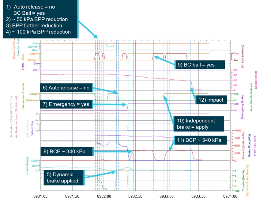
Source: ATSB (based on data supplied by RTA Weipa Pty Ltd)
Purpose of safety investigationsThe objective of a safety investigation is to enhance transport safety. This is done through:
It is not a function of the ATSB to apportion blame or provide a means for determining liability. At the same time, an investigation report must include factual material of sufficient weight to support the analysis and findings. At all times the ATSB endeavours to balance the use of material that could imply adverse comment with the need to properly explain what happened, and why, in a fair and unbiased manner. The ATSB does not investigate for the purpose of taking administrative, regulatory or criminal action. TerminologyAn explanation of terminology used in ATSB investigation reports is available here. This includes terms such as occurrence, contributing factor, other factor that increased risk, and safety issue. Publishing informationReleased in accordance with section 25 of the Transport Safety Investigation Act 2003 Published by: Australian Transport Safety Bureau © Commonwealth of Australia 2023
Ownership of intellectual property rights in this publication Unless otherwise noted, copyright (and any other intellectual property rights, if any) in this report publication is owned by the Commonwealth of Australia. Creative Commons licence With the exception of the Coat of Arms, ATSB logo, and photos and graphics in which a third party holds copyright, this publication is licensed under a Creative Commons Attribution 3.0 Australia licence. Creative Commons Attribution 3.0 Australia Licence is a standard form licence agreement that allows you to copy, distribute, transmit and adapt this publication provided that you attribute the work. The ATSB’s preference is that you attribute this publication (and any material sourced from it) using the following wording: Source: Australian Transport Safety Bureau Copyright in material obtained from other agencies, private individuals or organisations, belongs to those agencies, individuals or organisations. Where you wish to use their material, you will need to contact them directly. |
[1] Eastern Standard Time (EST): Coordinated Universal Time (UTC) + 10 hours.
[2] A set of wagons moved as a unit.
[3] kPa kilopascal, a unit of measure for air pressure.
[4] The locomotive had an operating cabin on either end. Cabin 2 was leading into Lorim Point and cabin 1 was leading departing Lorim Point.
[5] A designated person in charge of safe working operations for the railway corridor.
[6] A brake application in the normal operating mode, without using the emergency position.
[7] Braking that uses the momentum of the locomotive and train to cause a braking effect. The traction motors are in effect turned into generators and the power is dissipated as heat through fan blown grids on the locomotive.
[8] Maximum brake application made when a train must be stopped in the minimum distance possible, initiated by the driver or other crew member, or by a fault in the brake system such as rupture to the brake pipe, air hoses becoming disconnected, etc.
[9] Progress Rail acquired the Downer EDI freight business in 2018.
[10] The accident locomotive was fitted with a one-way telemetry system where data was only sent from the end of the train to the receiver in the locomotive.
[11] Actual wheel diameters were not provided to correct the speed and distance parameters, however. comparison to recorded GPS data provided confidence sufficient to complete this comparative analysis.
[12] Three trips were shorter with a different shunt pattern, likely due to re-fuelling of the locomotive.
[13] Standard gauge is nominally 1,435 mm.
[14] Lorim Point was an automated discharge station.
[15] The zone in which the indexing arms manage the movement of the rake.
[16] Rio Tinto Weipa Railway Operational Procedures Manual, version 1.6, dated 01/11/2017.
[17] Exemption dated 30 June 2020 for the fatigue requirements relating to rolling stock operations, specifically in Queensland only.
[18] Appendix 2, Specification for the purchase of new locomotive, section 9.2 Anti-climber and collision protection system, page 19, locomotive replacement contract 5600017129.
[19] GT42CU locomotive.


