Safety summary
What happened
On 24 October 2014, the Melbourne to Sydney XPT service ST24 was approaching Culcairn station when there was a severe vibration. The driver stopped at the station and upon inspecting the train found that the axle had broken adjacent to the bearing box on the fourth passenger carriage. There were no injuries to passengers or crew. The passengers continued their journey to Sydney on chartered buses.
What the ATSB found
The ATSB found that the axle bearing had failed and completely seized, probably due to cage failure.
The probable cage failure caused the rollers to misalign and seize. This seizure of the rollers generated friction and excessive amounts of heat into the bearing journal. The heat applied to the bearing journal caused it to go ‘plastic’ and separate from the axle (commonly referred to as a screwed journal). In this case, much of the evidence was either lost or damaged beyond useful examination. Consequently, there was insufficient evidence available to determine why the bearing cage may have failed.
The ATSB also identified that ARTC train control, despite receiving reports of trackside fires, made contact with NSW Trains operations, rather than directly with the driver. It is unlikely that direct communication with the driver of ST24 would have resulted in a different outcome in this case because, by the time the potential cause of fires was known, ST24 was already on its way to Culcairn. However, in some scenarios, communicating directly with the train driver would likely ensure a more timely response to issues that may affect the safety of the network.
What's been done as a result
ARTC will ensure that all matters relating, or potentially relating to, the safety of a train operating on the network will be advised in the first instance to the driver of the involved train by the relevant Network Control Officer.
Safety message
Any issues with train services that can compromise the integrity and safety of the network must be communicated directly to the train driver. Communicating through a third party can compromise a timely response.

Source: Sydney Trains
At about 0700[1] on October 24 2014, TrainLink[2] Sydney to Melbourne passenger service ST21, operated by NSW Trains,[3] arrived at Broadmeadows[4] Victoria (Figure 1). At Broadmeadows, there was to be a crew change and passengers disembarking the service.
As ST21 arrived at Broadmeadows, the relief driver, who was waiting on the platform, noticed what the driver described as a strong smell of brakes. During the handover briefing, the two drivers discussed the smell coming from the train. Although a smell coming from the brakes was common on long trips, the relieving driver, now in charge of the train, decided that he would undertake further inspection at McIntyre. McIntyre is located between Broadmeadows and Southern Cross station and was where refuelling of the return service to Sydney occurred.
At McIntyre, the train was re-fuelled and cleaned in readiness for the return journey to Sydney, with a new train identification number of ST24. While re-fuelling, the driver also examined the area of the train thought to be the source of the smell, paying particular attention to the brakes. While he again noticed the brake smell, he did not consider it unusual for a train having just completed a trip from Sydney. He then readied the train, departed McIntyre and arrived at Broadmeadows at about 0835 to pick up passengers. At about 0855, train ST24 departed Broadmeadows for Sydney with 125 passengers and crew on-board.
Figure 1: Location of Broadmeadows, Benalla, Winton, and Culcairn.
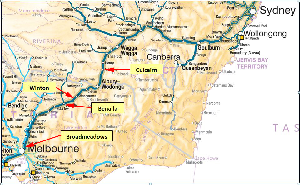
Source: Geoscience Australia annotated by the ATSB
At about 1041, ST24 arrived at Benalla station, stopping briefly to set down and pick up passengers. At about 1106, ST24 undertook another passenger stop at Wangaratta before continuing on to its next scheduled stop at Albury.
At about 1123, the Emergency Service Telecommunications Authority (ESTA known as ‘000’) received a phone call from a member of the public, advising of a fire between the Hume Hwy and the railway line about 5 km north of Benalla. After confirming the location, the operator dispatched the Country Fire Authority (CFA) to attend the scene. For the next 20 minutes, passing motorists and members of the public in the Benalla Winton area, reported more spot fires to 000.
At about 1143, the Australian Rail Track Corporation (ARTC) Train Transit Manager (TTM) at Junee Train Control Centre, NSW received a call from the CFA. The CFA reported that a fire in the Winton area was adjacent to the railway line.
Soon after, ST24 arrived at Albury station to set down and pick up passengers, then departed Albury for Culcairn at about 1153.
At about the same time, the ARTC TTM received another call from the CFA reporting that crews were attending the trackside fires. The CFA suggested that the last train through the area (about 30-45 minutes prior) had started the fires. The TTM advised that, at about 1100, a northbound passenger train (ST24) had passed through that area. The CFA re-affirmed their belief that this train had started the fire, as no other fires had been reported anywhere other than the Winton area. The TTM advised that he would contact TrainLink operations in Sydney and get them to make enquiries with the driver of ST24 about its possible connection with the Winton fires.
The TTM contacted the NSW Trains Daily Operations Continuity Centre (DOCC) Operations Manager and informed him of the fire in the Winton area. The TTM explained that the only train through that area in the last 50 minutes was the XPT Melbourne to Sydney service ST24 and that this train may have caused the fire. The Operations Manager informed the TTM that he would contact the driver of ST24 and make further enquiries regarding any problems with the train.
At around 1200, the NSW Trains Operations Manager contacted the driver of ST24 to inform him of a fire in the Winton area. He told the driver that the TTM in Junee had contacted him after they had received a report from the CFA regarding a fire adjacent to the track in the Winton-Benalla area. He told the driver that they believed his train had started it and asked if he had any issues with his train. The driver reported that everything seemed to be okay, but would inspect his train at his next scheduled stop.
The DOCC Operations Manager then contacted the TTM and informed him that he had spoken directly to the driver of ST24 and the driver reported nothing wrong with his train. He also advised that the driver would check it at the next scheduled stop.
At about 1213, the driver of ST24 experienced what felt like a run-in,[5] which he considered unusual for the approach into Culcairn. At about the same time, the driver heard (over the radio) the Passenger Attendant (PA) report to the Passenger Services Supervisor (PSS) of a severe vibration in the first class passenger car. Shortly thereafter, the PSS contacted the driver and advised that something was wrong with the first class passenger car. The PSS described it as a severe vibration, as if the passenger car was running over something.
At this stage, ST24 was approaching Culcairn. The driver determined that the train was still coupled and on the rails, so he decided to continue on the short distance to Culcairn.
At about 1216, the driver stopped the train at the station and notified Train Control (TC) that he was in clear[6] at Culcairn. He also advised that he was going to inspect the train, as the PSS had reported vibration in a passenger car. He asked for the departure signal to be placed at stop and asked for permission to access the track to inspect the train.
After inspecting the train, the driver notified TC that the trailing axle on car B (XL2235) had sheared off (Figure 2). He informed TC that the train was unable to continue its journey and alternative arrangements would be required for passengers to continue their journey. During the conversation, TC informed the driver of other reported fires in the Albury and Gerogery areas.
Figure 2: Failed axle and swing arm hanging down.
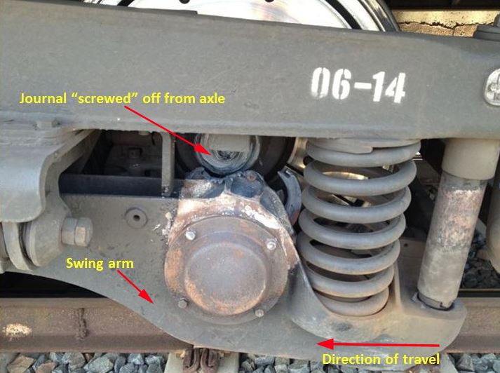
The image shows the failed axle journal, commonly referred to as a ‘screwed journal’. As the bearing housing no longer supports the axle, the swing arm has dropped. Source: NSW Trains, annotated by the ATSB
Events post-derailment
Passengers continued their journey on buses. The Australian Rail Track Corporation (ARTC) and NSW Trains examined options for moving the train to a siding at Culcairn. Once a suitable solution was identified, the damaged car was moved to the siding where it remained until arrangements could be made to replace the defective bogie. The remainder of the train then continued to Sydney.
It is likely that a progressively failing bearing on ST24 caused a number of fires beside the track. The fire services attended the fires, while the police attended the scene at Culcairn.
The ARTC arranged for an inspection to ensure the track had not been damaged by the dragging swing-arm. There was no damage to the track infrastructure.
__________
- The 24-hour clock is used in this report to describe the time of day, Eastern Daylight saving Time (EDT).
- Previously operating as CountryLink
- NSW Trains is an operating agency of Transport for NSW, responsible for the operations of the XPT services.
- XPT services were terminating at Broadmeadows due to the track works at North Melbourne as a result of an earlier derailment (see ATSB report RO-2014-013).
- When the rear section of a train is travelling faster than the forward section of the train often results in a run in. The run in occurs where the difference in speed takes up all the slack parts of the train and the sudden match in speed results in a jolting movement.
- A train is ‘in clear’ when it is within the clearance point boards for the crossing purposes, or when the entire train is within station protection and is not foul of an adjacent track.
Location
The failed axle occurred near Culcairn (NSW), about 357 km [7] from Melbourne (Figure 1). The line, referred to by Train Control Junee as Main Line South, forms a main arterial link between Sydney and Melbourne.
The first reported fire occurred near Winton in Victoria (Figure 1) located at about the 207 km point.
Train information
The Express Passenger Train (XPT) is a ‘push-pull’ configured train with a power car at each end of the consist. The XPT was introduced in 1982 and is based on the InterCity 125/Class 43 design used in Britain.
Figure 3: XPT TrainLink power car XP2001.

The image shows an XPT power car and passenger car. ST24 consisted of five passenger cars, identified by the letters A-E, with a power car both leading and trailing. Source: ATSB
Sydney Trains owns the XPT fleet. NSW Trains is the operating agency providing passenger services through country NSW and to Brisbane, Canberra, and Melbourne.
The XPT train (ST24) consisted of a 5-car set with power car XP2001 leading and XP2016 trailing.
Train crew information
At the time of the incident, there were seven train crew on board, including the train driver. The driver of ST24 had over 13 years driving experience with 7 years driving XPT trains. The driver was tested for drugs and alcohol, and returned zero readings.
Train handling
The XPT power cars are fitted with Hasler tape data logging devices. Hasler data loggers record:
- time, speed, distance
- throttle position (power/idle)
- vigilance acknowledgement
- brake cylinder pressure.
Of the two devices, the data logger in XP2016 (trailing car) was fully functioning. The recording for the leading power car, XP2001 was incomplete in that it did not record distance or brake cylinder pressure correctly.
The data logged from XP2016 was validated against train control graphs for distance travelled. The brake cylinder pressure could not be validated against XP2001 data logger. However, the recorded brake cylinder pressures changes indicate a consistent deceleration pattern with similar changes seen in the recorded BCP during all braking sequences on XP2016.From the evidence available, it was determined that the train handling was generally consistent with common train handling practices.
Refuelling
The XPT trains require mid-journey refuelling for the service from Sydney to Melbourne and return. During the re-fuelling at McIntyre, the driver of ST24 also looked for any issues that may have caused the brake smell observed at Broadmeadows.
Due to the train’s position, it was not safe to check its left hand side (in the direction of travel to Sydney) because of the adjacent live track. However, the driver did check the right hand side of the train, checking cars A, B, and C (Melbourne end - last three carriages). During these checks, the driver did not see any signs of the journals or bearing boxes being abnormal but noted that there was a smell and the brakes were warm. However, the driver did not think it was out of the ordinary, as the train had just completed a journey of over 1000 km.
Track information
The Main Line South track is a standard gauge track[8] consisting of continuously welded rail on concrete sleepers, fastened by resilient clips.
The ARTC lease and manage the track. Control for the Main Line South signalling is from the ARTC Train Control Centre at Junee.
Track speed approaching Culcairn station is 160 km/h for XPT services. The service only stops at Culcairn when passengers are scheduled to disembark or board the service.
Bearings
The bearings used on the XPT fleet are Timken SP120 package tapered roller bearing. Package bearings consist of two tapered bearing assemblies (commonly referred to as cones, and includes the inner rings, rollers and cage). Between the two bearing assemblies is a spacer ring of specific width, correctly positioning the two cones when the bearing is assembled. Outside each bearing assembly is a seal wear ring, over which the grease seal is positioned. When installed in the wheel-set, a backing ring is mounted on the inboard side of the axle journal and an end-cap is bolted onto the outer end of the bearing journal (Figure 4).
Figure 4: Package bearing components
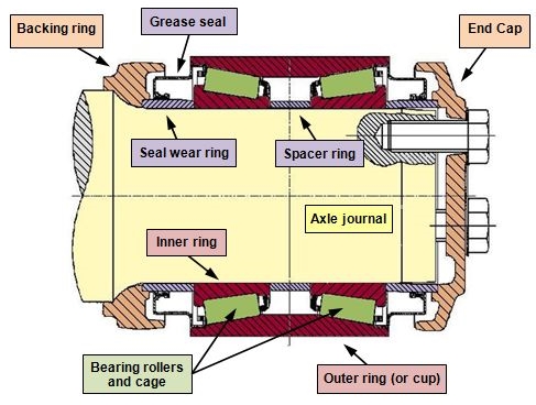
Source: ATSB
The Engineering Instruction for TrainLink wheelsets requires the bearings to be put into service within two years of manufacture or requalified date. If the date is more than two years, the bearings are required to have the grease replaced.[9]
Package bearings are installed as fully greased sealed units and are press fitted onto the journal at Unipart UGL in Auburn. The bearings do not require in-service regreasing, which reduces the risk of inadequate, excessive, or contaminated lubricant during operation.
Bearing history
Timken bearings supply new SP120 bearings to Bearing Engineering Services[10] (BES), which then supply UGL Unipart bearings for the XPT fleet. BES also service and requalify bearings for reinstallation.
Combinations of new and requalified bearings were installed on passenger car XL2235. The new bearings were manufactured in South Africa in 2012. These bearings were supplied to UGL with Renolit MP3 grease, as installed by the manufacturer. The requalified bearings were overhauled in 2013 (by BES) and supplied to UGL with Timken premium railroad grease.
The bearing installed into position 3 (Figure 5) on bogie NHA-8B in June 2014 was a new bearing. The serial number of the bearing was 302379 with a manufacture date of July 2012.
At the time of its failure, the bearing was well within its service life of 375,000 km.[11]
Figure 5: Bearing position on bogie NHA-8B
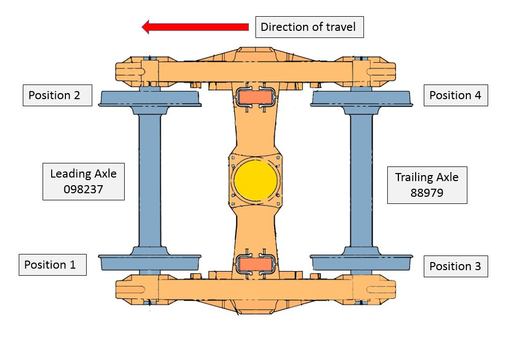
Source: ATSB
Bearing and axle examination
The bogie was taken to the UGL Unipart in Auburn for examination. Preliminary examination of the failed bearing components by the ATSB indicated that the bearing had seized. The remains of the bearing and the accompanying swing arm were taken back to ATSB laboratory for further analysis. The remains of the axle journal were not recovered.
It was evident that the bearing had seized while the axle was still turning. The heat generated by the failed bearing was sufficient to heat the journal, to make it ‘plastic’ (Figure 6) and cause it to separate from the axle (commonly referred to as a screwed journal).
Figure 6: Swing-arm bearing housing
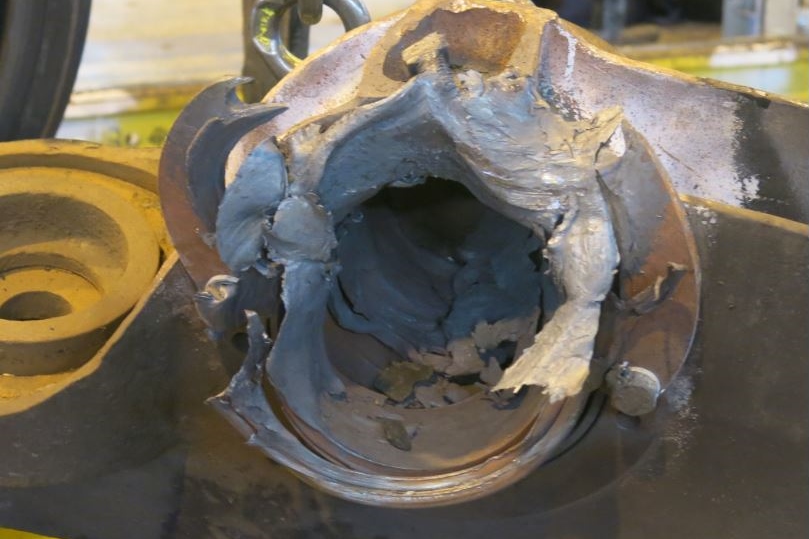
The XPT bogie swing-arm bearing housing, viewed from the inboard side. The heat damage is evident and the remaining bearing components can be seen inside the housing. Source: ATSB
The ATSB failure analysis specialists conducted an examination of the failed bearing. Witness marks at the interface between the bearing and the swing-arm bearing housing could not be examined due to the extensive damage to the bearing.
There were a number of flat rollers on the inboard (Figure 7-1) and the outboard (Figure 7-3) bearings. Markings on the flattened rollers indicate that the rollers seized and misaligned in the bearing cage while the axle was rotating.
The inboard raceway showed evidence of full-width spalling[12] fatigue (Figure 7-2). The spalling fatigue began from the 6 o’clock position and continued in the direction of rotation to the 9 o’clock position. There was also some fracturing of the shoulders on the unworn surfaces of the track.
The outboard raceway showed a full-width area of galling[13] and deposited metal (Figure 7-4). Galling is usually associated with a lack of lubrication, resulting in the two metal surfaces welding together for brief periods.
Figure 7: Remains of the failed bearing
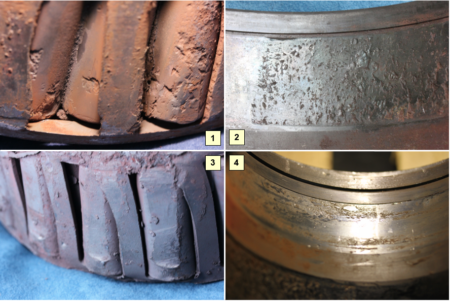
Image 1: Inboard cone, showing flattened, misaligned rollers with spalling fatigued surfaces.
Image 2: Inboard raceway, showing full-width spalling fatigue.
Image 3: Outboard cone, showing flattened rollers.
Image 4: Outboard raceway showing full-width galling and deposited metal. Source: ATSB
The investigation also examined the partner bearing from the opposite end of the axle.
The partner bearing was removed from the journal and the end cap bolt torque measured. The torque values were consistent with the maintenance requirement. Initial observations indicated that the partner bearing was generally in good condition.
Partner bearing examination by BES
BES conducted an examination of the partner bearing, with the ATSB present.
The bearing was weighed and grease samples from the inner, outer and spacer (centre) of the bearing was taken and sent for analysis. The BES examination found that the bearing showed uneven adaptor fretting[14] marks on the cup exterior (Figure 8-1). There was also wear and damage to the inboard raceway (Figure 8-2) and outside edges of the inboard cone rolling elements (Figure 8-3). Conversely, the raceway and rolling elements of the outboard cone (Figure 8-4) were in good condition.
Based on the amount of fretting on the bearing cup BES concluded that the bearing was probably misaligned (unevenly loaded) from when the bogie was put into service.
Figure 8: Partner bearing
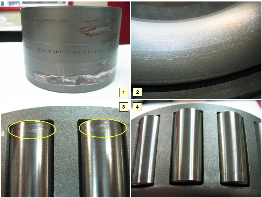
Image 1: Uneven fretting marks on the exterior of bearing cup indicating uneven contact pressure between the bearing cup and the swing-arm bearing housing.
Image 2: Indentation damage to the inboard raceway.
Image 3: Peeling damage to the rolling elements of the inboard cone, predominately on the outside edges due to uneven loading.
Image 4: Undamaged rolling elements from the outboard cone. Source: BES
During the BES examination, ATSB investigators took grease samples from the partner bearing for analysis. After the BES examination was completed, ATSB investigators retained the partner bearing for further analysis.
Partner bearing examination by the ATSB
An ATSB failure analysis specialist examined the partner bearing components using an illuminated magnifier and with a stereomicroscope.
Outer cone
The outer cone had limited wear with fine brinelling,[15] scoring and polishing. This wear was also evident in the analysis of the grease samples. The samples contained iron but not chromium from alloy steel (the rollers, cup, and cone). The wear had mostly come from the soft, plain-carbon steel cage.
Inboard cone
The results of the inboard cone analysis contrasted with that of the outboard cone, with significantly higher presence of chromium from the alloy steel cup, cones and rollers.
The examination found evidence of metal loss to the bearing spacer and inner rear enclosure. The wear on the spacer would likely have resulted in some loss of preload on the bearings resulting in excessive end float. Increased end float would have placed uneven loading on the bearing, in particular the back-face end of the inner cone/double cup. It is possible that this point on the partner bearing acted as a fulcrum when the axle journal failed and the opposite end of the axle became unsupported.
The rollers of the inboard cone showed evidence of adhesive wear, but only at the back-face end. This corresponded with the inboard raceway, which exhibited a worn shoulder with several bright areas of spalling.
Swing-arm Bearing Housing
The swing-arm bearing housing showed heavy fretting wear that corresponded with asymmetric fretting wear on the bearing cup (Figure 9). Also observed, was the crack in the upper half of the bearing housing (Figure 10).
Figure 9: Partner bearing (position 4) serial number 302111
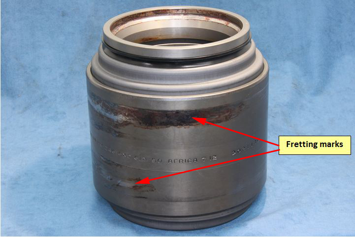
The corresponding fretting marks found on the partner-bearing cup was also evident on the partner swing arm. Source: ATSB
Figure 10: Swing arm assembly with exploded view of the bearing housing bore below
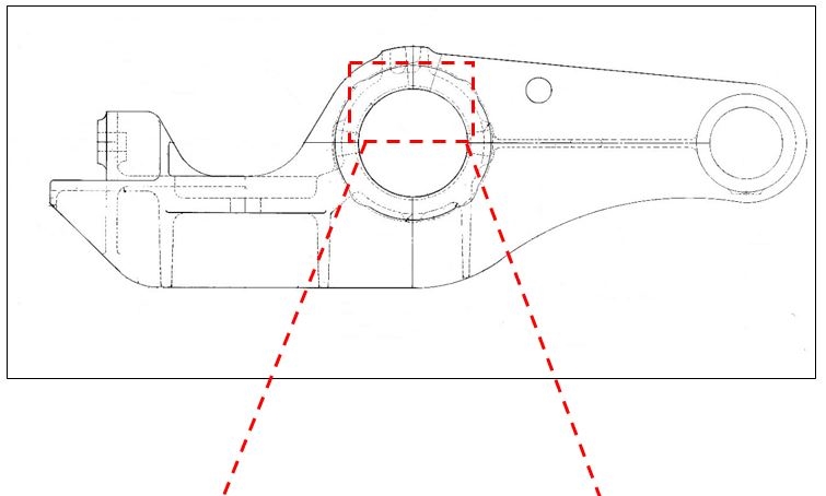
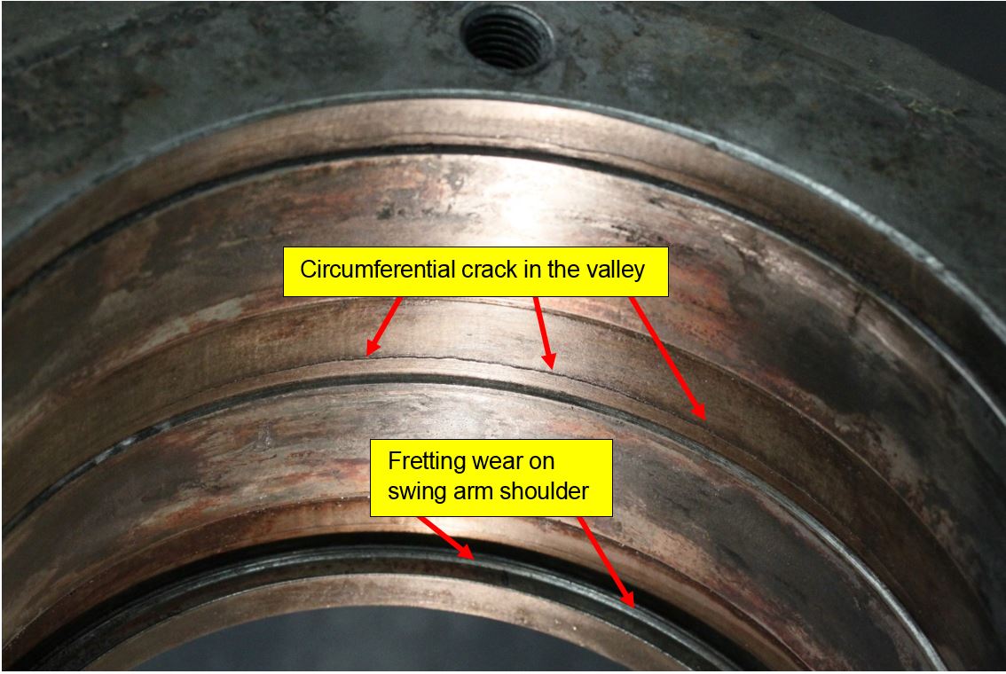
Figure 10 is of the partner swing arm (from the same axle). The exploded view shows the fretting wear on the swing arm shoulder evident by the shiny marks as annotated. As illustrated, there is also a crack in the valley of the housing. Source: ATSB
These wear patterns provided further evidence of uneven loading, possibly due to the axle misaligning when the axle journal failed and the opposite end of the axle became unsupported.
When matching the bearing cup witness marks to those in the swing-arm bearing housing, the marks ranged from a 9-3 o’clock position and were asymmetric in nature. This indicated that there might have also been some misalignment in the horizontal plane (Figure 11).
Figure 11: Bearing position on bogie NHA-8B
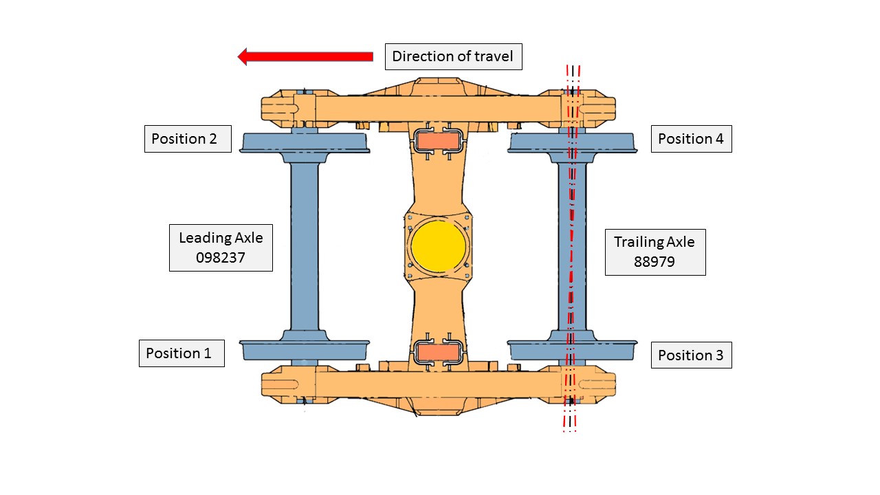
Figure 11 is for illustrative purposes and not a direct representation of an XPT bogie. The black dotted line on the trailing axle represents the centreline of the axle when running true. The red line illustrates a misalignment of the trailing axle, in the horizontal plane. Source: ATSB
The ATSB concluded that there was evidence of uneven loading. However, there was insufficient evidence to determine if the misalignment was predominantly in the horizontal or vertical planes.
When considering the physical evidence and examinations by both BES and ATSB specialists, the most likely conclusion is there was a misalignment in the axle. However, there was insufficient evidence to determine if this was a pre-existing condition or if it occurred because of the bearing failure.
There were no conditions associated with the partner bearing (position 4) that would suggest a possible cause for the failure of the bearing in position 3.
Grease analysis
The type of grease used by Timken in the new bearings is Renolit MP3 grease. The operator’s Engineering Standard for grease used in journal bearings for seal and package units requires that the grease be approved by the Association of American Railroads (AAR). Renolit MP3 grease is not approved by the AAR in this application. However, the grease has almost identical properties to that of an AAR approved grease type such as Timken premium railroad grease. There is no evidence that the use of Renolit MP3 grease contributed to the failure.
Partner bearing grease analysis
The partner bearing grease samples were sent to the ALS Laboratory Group for analysis. The results showed a mid-range content of silicon (contaminant) and higher levels of iron from the centre (spacer ring) grease sample, mid-range chromium and silicon with higher levels of iron from the inboard sample and low levels of chromium with mid-range levels of silicon and higher levels of iron from the out-board sample.
The chromium levels from the inner and outer grease samples indicate that it was liberated most likely from the inner and outer cup and because of the peeling damage from the inboard cone roller faces. Indentation marks on the inner and outer race was evident from the BES report and ATSB analysis.
The iron found in all three samples is likely to be from the roller cage as a result of the axle failure placing more stress on the partner bearing.
Although the grease analysis showed high levels of contaminants and iron it is likely this is due to the failed axle.
Examination of the partner bearing grease found no condition or anomaly that could be directly related to a potential issue with the corresponding failed bearing.
Bearing failure types
The recovered bearing components were examined in relation to the common failure modes for railway bearings.
A loss of interference fit between the bearing and axle journal often occurs later in the failure sequence. That is, other faults may combine to cause progressive loss of interference fit. Initial slippage may be small, but as the journal wears, the amount of slippage increases.
However, if a bearing seizes, slippage of the inner ring on the journal can suddenly occur.
Lubrication failure
The function of a lubricant is to separate the rolling contact surfaces at the point of high-pressure contact. The lubricant film between the surfaces acts to reduce wear, friction and corrosion such that the bearing should achieve its predicted fatigue life; assuming that no other factors exist that may cause premature failure. Lubrication failure can occur due to an inappropriate grade of lubricant, insufficient lubricant or contamination of the lubricant.
Cage failure
The bearing cage is designed to retain the rollers within the bearing in a consistently spaced and correctly aligned position. The cage has no role in the transmission of forces. The cages in bearings used in the railway industry are usually pressed out of metal plate.
The purpose of roller bearings is to avoid sliding friction. However, sliding at the cage surfaces cannot be avoided. Consequently, the softer material of the cage (when compared to other components) is likely to be the first area to wear when lubrication becomes inadequate or foreign material causes abrasion. Once wear occurs, the cage loses the ability to align the rollers correctly and leads to a rapidly deteriorating cage resulting in a complete failure of the cage. Once the cage fails, material jams the rollers, generating heat and the bearing inevitably fails.
Bogie NHA-8B maintenance
UGL Unipart, located in Auburn NSW, is the contracted maintenance provider for XPT bogie refurbishments. XPT carriage bogies are overhauled every 750,000 km with the wheelsets overhauled every 375,000 km. New or requalified[16] bearings are fitted with the changed out wheelsets.
The ATSB examined the maintenance records of bogie NHA-8B. The records show that during the assembly and overhaul of the bogie, all components and relevant measurements meet the requirements of the XPT carriage NHA Bogie Overhaul Specification RX01_0200_123MP.
In June 2014, passenger car XL2235 had the overhauled bogie NHA-8B fitted to the B end of the passenger car. The failed axle of the bogie set (the trailing axle in this case) had new bearings installed. The lead axle assembly had requalified bearings.
In-service inspection and maintenance
XPT carriages undergo trip inspections either at 2-day intervals or at 3000km, and maintenance every 90 days.[17] Both inspection intervals include the testing of axle box temperatures (by feel) as the train is being fuelled and decanted.
Axle boxes are also inspected for:
- loss of lubricant at rear axles seals
- discolouration indicating overheating.
During the operation of carriage XL2235 on 15 August 2014, a defect was noted on bogie NHA-8B on the power car logbook[18]. The defect was reported as a ‘whirring’ noise from beneath the car and the axle boxes were warm to touch. The defect was inspected on the next scheduled service on 16 August 2014 and no issue was found. The carriage was returned to service without any further noted defect regarding whirring noises or warm axle boxes.
The last documented trip inspection was on 23 October 2014 with no issue recorded. Analysis of the maintenance documentation including the defect history and inspection records indicated that there were no pre-existing maintenance issues identified with bogie NHA-8B.
Condition monitoring systems
Condition monitoring systems can be split into two generic types, reactive and predictive. These are akin to reactive and preventative maintenance. A reactive approach requires an immediate action after a serious condition develops or equipment failure occurs, whereas a predictive/preventative approach identifies the requirement for future action before a serious condition develops.
Reactive condition monitoring, such as hotbox detectors, are usually used as a ‘last line of defence’ to protect significant or critical railway infrastructure assets. They are usually used on track associated with production processes such as coal and ore carrying railways, but less common on mixed freight/passenger tracks such as the interstate main lines (refer to appendix A).
In this case, there were no reactive condition monitoring systems in place that could have detected the imminent failure of the bearing on XPT service ST24.
Infrastructure managers and rolling stock operators have directed more effort towards predictive condition monitoring of railway rolling-stock travelling on the interstate main lines. With regards to bearing condition monitoring, the predictive systems adopted are Bearing Acoustic Monitoring (BAM) systems (refer to appendix A).
Being a predictive condition monitoring system, multiple passes of potentially defective bearings are required for trends to be clearly identified and actioned before a defect reaches a critical level. Consequently, the systems are positioned throughout the interstate network based on major rail corridors. For the Sydney-Melbourne corridor, the BAM system was located on the Main South up line at Exeter, NSW (about 155 km from Sydney).
Examination of the BAM data for XPT passenger car XL2235 found no evidence of acoustic signatures to suggest the onset of a bearing failure.
__________
- Distance in kilometres from Southern Cross Station, Melbourne.
- The name given to the gauge of track 1435mm wide between running rails.
- State Rail Authority Engineering Instruction EIDSS 5152 requires that any new or recondition bearing should not be used if a shelf storage period of greater than 24 months has occurred since manufacture or reconditioning date. Bearings in this condition shall be returned to a qualified bearing reconditioner to have the grease replaced prior to being installed onto the axle.
- BES is a division of the Schaeffler Group and is the supplier of new and requalified bearings to UGL Unipart.
- Bearings are replaced with wheelsets as per maintenance schedules for 375,000 km or if there is a defect wheelset. Bearings removed from defective wheelsets are not placed back into service until they are inspected and are suitable to be requalified.
- The cracking and flaking of particles out of a surface
- A condition whereby excessive friction between high spots result in localised welding with subsequent spalling and a further roughening of the rubbing surfaces of one or both of two mating parts
- Wear that occurs between tight fitting surfaces subject to oscillation at very small amplitude. This type of wear can be a combination of oxidative wear and abrasive wear.
- Damage to a solid bearing surface characterised by one of more plastically formed indentations brought about by overload. The term is often applied in the case of rolling-element bearings.
- Requalified bearings involves the, disassembly, cleaning, inspection, repair, (if necessary) and reassembly of the roller bearing components to the manufacturer’s specifications. Bearings are scrapped when they are over 10 years old.
- General (major) inspections are balanced over four inspection cycles and then repeated for the XPT fleet. Each 90-day major inspection contains 360 and 180-day inspection items to enable an even workflow over half the inspection cycle and then repeats over the complete inspection cycle,
- Power car logbooks are located in the power cars and are used by train drivers to record any faults noted during the running of the service.
Bearing failure
In this case, much of the evidence that may have indicated the cause of its failure was either lost or damaged beyond useful examination. However, the absence of BAM data indicating a developing bearing fault would suggest that the bearing on XL2235 experienced a relatively quickly developing fault resulting in catastrophic failure. Consequently, failure modes such as metal fatigue, rolling surface defects and loose bearing components are less likely to have been failure initiators.
Examination of the partner bearing provided no clear indication of a failure mode that may have resulted in the failure of the bearing on XL2235. However, some iron particles where found in the grease indicating wear on the bearing cage. There was also evidence of uneven loading due to misalignment of the axle. However, there was insufficient evidence to determine if this was a pre-existing condition or if it occurred because of the bearing failure.
As most failure modes were considered less likely, the most probable cause of the bearing failure was a cage failure. The cage failure caused the bearing rollers to become misaligned and subsequently seize in the bearing housing. The seizure then caused friction resulting in excessive heat to build up in the bearing housing within the swing arm and journal. This generated enough heat into the bearing journal to cause it to go ‘plastic' and separate from the bearing journal.
Bearing cages may fail due to lack of lubrication, bearing misalignment (uneven loading), shock loading (wheel impacts), or a combination of these conditions. In this case, there was insufficient evidence available to determine why the bearing cage may have failed.
Reports of trackside fires
While in Melbourne, the driver of XPT train ST24 noticed a strong smell typical of hot brakes. The driver inspected the train before departure, but found nothing of concern. The investigation found no other precursor events or conditions that might suggest imminent failure of a bearing on XPT car XL2235 prior to its departure from Melbourne. However, there were events reported during the journey that may have suggested a potential problem with XPT train ST24.
After the passage of ST24, several fires were reported to the fire authorities, which required fire crews to attend.
The first report to the ARTC train control centre was of a fire in the Benalla-Winton area. Soon after, train ST24 arrived at Albury, set down and picked up passengers, then departed Albury for Culcairn. At about the same time, the Country Fire Authority made a second call to the ARTC.
The reported fires were all in close proximity to the track, suggesting that a train had started them. The timing and sequence of the reports suggested that train ST24 had started the fires, as it was the last train to have travelled through that area. It is likely that the failing bearing liberating hot components that consequently started the fires.
Following the second call from the Country Fire Authority, the ARTC TTM contacted the NSW Trains operations manager to advise that there may be a problem with their TrainLink service ST24, and requested them to check their train.
County Link operations contacted the driver of ST24 as he was travelling through the Table Top area advising him of the fire in the Benalla-Winton area. About 15 minutes had passed between the first report to train control and the request for the driver to check the condition of train ST24.
The North Albury and Gerogery fires were reported to train control when ST24 was already at Culcairn. There were no other fires reported on the Main Line South between Winton/Benalla and Sydney for that period.
It is likely that heat generated by a progressively failing bearing on ST24 had started a number of trackside fires. While the fires were reported to train control, there was no direct communication with the driver of ST24.
Communications between train control and ST24
TrainLink XPT trains have mobile phones fitted to every power car that use the Telstra mobile network.
An examination of phone records show that the calls made to the lead power car of ST24 were from the NSW Trains Daily Operations Continuity Centre (DOCC) in Sydney. Phone records obtained from ARTC and Sydney Trains confirm that at no stage prior to the axle failure did ARTC train control contact the driver of ST24.
ARTC Emergency Management
ARTC has an emergency management procedure (TA44) which outlines the management of emergencies within the ARTC rail network. The procedure addresses trackside fires and the management of the network and trains that may be affected by that fire. In short, the Train Transit Manager (TTM) or nominated representative takes the role of the Incident Response Coordinator, responsible for advising the relative parties such as emergency services and train operators of the incident.
In this case, the TTM assumed the incident response coordinator’s role when advised of the fire in the Benalla-Winton area. The TTM then liaised with the CFA control centre to ascertain the position of the fire and if CFA officers were on or near the track.
With respect to a fire in or near the rail corridor, it was evident that the procedures documented in procedure TA44 were intended to manage potential damage to infrastructure, and to manage the risks associated with fire crews working near the rail track. The procedure did not include consideration of the potential cause of a fire.
Requirements under Network Rule ANTR 402
Network rule ANTR 0402 ‘Inspecting trains’ covers inspecting of trains during travel in NSW. The Inspection during travel rule states that:
If unsafe conditions or defects are reported to Network Control, a Network Control Officer must:
- Tell the affected Train Crew about unsafe conditions and defects, and
- Follow the requirements of Rule ANGE 206 Reporting and responding to a Condition Affecting the Network
An equivalent requirement is not specifically documented in the rules applicable to Victoria.
In this case, the ARTC received advice from the CFA that they believed a train that had started the fires at Winton. By this time, ST24 had just departed Albury and was travelling towards Culcairn. The ARTC contacted a third party (DOCC) requesting a check of train ST24, rather than directly contacting the train crew.
It is unlikely that direct communication with the driver of ST24 would have resulted in a different outcome in this case because, by the time the potential cause of fires was known, ST24 was already on its way to Culcairn. However, in some scenarios, communicating directly with the train driver would likely ensure a more timely response to issues that may affect the safety of the network.
The ATSB identified a similar issue during another investigation.[19] In that incident, it was apparent that the use of a third party was common for facilitating communication between Network Control Officers and train drivers.
__________
From the evidence available, the following findings are made with respect to the axle failure on XPT ST24 on 24 October 2014 at Culcairn NSW. These findings should not be read as apportioning blame or liability to any particular organisation or individual.
Safety issues, or system problems, are highlighted in bold to emphasise their importance. A safety issue is an event or condition that increases safety risk and (a) can reasonably be regarded as having the potential to adversely affect the safety of future operations, and (b) is a characteristic of an organisation or a system, rather than a characteristic of a specific individual, or characteristic of an operating environment at a specific point in time.
Contributing factors
- The XPT axle failed when the bearing seized, generating enough heat for the bearing journal to go ‘plastic’ and separate from the axle, a condition commonly referred to as a ‘screwed journal’
- In the absence of any evidence to the contrary, the most probable cause of bearing seizure was failure of the bearing cage. This likely allowed the rollers to misalign and jam, resulting in slippage of the inner bearing ring on the journal.
Other findings
- There was insufficient evidence available to determine why the bearing cage may have failed.
- It is likely that a progressively failing bearing on ST24 caused the trackside fires reported to the ARTC train control.
- On receipt of the initial advice of the fire at Winton ARTC promptly communicated with the NSW Trains Operations Manager. However, direct contact with the Driver of ST24 would have been more appropriate.
- The grease used by the bearing manufacturer in the new supplied bearings was not an approved grease as documented in ESR 0400 Engineering Standard for bearing grease.
- The Hasler data logger in lead power car XP2001 was defective in that it was not recording brake cylinder pressure or distance.
Additional safety action
Whether or not the ATSB identifies safety issues in the course of an investigation, relevant organisations may proactively initiate safety action in order to reduce their safety risk. The ATSB has been advised of the following proactive safety action in response to this occurrence.
Additional safety action taken by ARTC
ARTC will ensure that all matters relating, or potentially relating to, the safety of a train operating on the network will be advised in the first instance to the driver of the involved train by the relevant Network Control Officer.
Sources of information
The sources of information during the investigation included the:
- Transport for NSW
- Sydney Trains
- UGL Unipart
- Australian Rail Track Corporation
- NHA-8B Bogie Overhaul maintenance documentation
- XPT Power Car Log Books for ST24
- Trailer car (XL2235) inspection sheets
- BES Bearing Inspection reports for remanufactured bearings
References
Queensland Rail Train handling manual SRD/0063
XPT Trailer Car NHA Bogie Overhaul Specification RX01_0200_123MP Version 1.0
ESR 0400 Specification for the Journal Bearing Oil & Multi-Purpose Grease
MJI-EB98 Rev 17 Countrylink Wheelsets – Inspection, Repair, Assembly and Scrapping
ARTC Emergency Management procedure TA44
ARTC Network Rule ANTR 402 Inspection trains
RISSB Glossary of Railway Terminology Version 1.0
Sydney Trains XPT Inspection Schedule & TMP Inspection Timetable
ASM Handbook, Volume11, Failure Analysis and Prevention
State Rail Authority Engineering Instruction EIDSS 5152 22 November 2004 issue 2
Submissions
Under Part 4, Division 2 (Investigation Reports), Section 26 of the Transport Safety Investigation Act 2003 (the Act), the Australian Transport Safety Bureau (ATSB) may provide a draft report, on a confidential basis, to any person whom the ATSB considers appropriate. Section 26 (1) (a) of the Act allows a person receiving a draft report to make submissions to the ATSB about the draft report.
A draft of this report was provided to Transport for NSW, Sydney Trains, the driver of train ST24, NSW Trains, Bearing Engineering Services, the Australian Rail Track Corporation, and The Office of National Rail Safety Regulator (ONRSR).
Appendix A – Condition monitoring systems
Hot-box detectors
Hotbox detectors are a reactive method of condition monitoring. They usually detect the infrared signature of bearing components and alarm if the temperature exceeds a predetermined setting. However, there are a number of variables that can affect their performance on a mixed freight/passenger rail corridor. These variables include but are not limited to:
- train loading
- train speed
- weather conditions.
Consequently, hotbox detection is usually used as a ‘last line of defence’ to protect railway infrastructure assets critical to production processes such as coal and ore carrying railways.
Due to the potentially unreliable performance of hotbox detectors under mixed freight/passenger conditions, more effort has been directed towards predictive condition monitoring of railway rolling stock travelling on the interstate main lines.
Bearing Acoustic Monitoring
Bearing Acoustic Monitoring (BAM) is a predictive condition monitoring system that ‘listens’ to the acoustic signature of bearings and can detect faults as they develop. It is the primary method for detecting potential bearing faults on rolling-stock travelling on the interstate main line. Recorded data from each train is stored in a database allowing evaluation, trending, and maintenance scheduling of rolling-stock based on predicted bearing condition.
BAM uses sensitive acoustic arrays to record the sounds emanating from wheels and bearings passing through the monitoring site. The recordings are processed for the sound characteristics that are unique to specific types of bearing faults. BAM is best at detecting faults on rolling surfaces such as the inner and outer raceways, and rollers in rolling-stock bearings. BAM can also detect looseness or fretting faults and ‘noisy’ wheels (flanging and wheel flats).
BAM systems are usually installed and maintained by infrastructure managers. However, the data is made available to rolling stock operators through a web interface. The BAM database categorises potential bearing faults in the form of levels of severity (1, 2, and 3 with level 1 being the most critical). The database allows operators to analyse bearing fault history and trends in order to plan their preventative maintenance strategies.
As for any monitoring system, there are some limitations. For example, BAM is a system that ‘listens’ for bearing noises, and under some conditions, other noises (rubbing equipment, tread defects or flanging wheels) may affect the results. However, being a predictive condition monitoring system, multiple passes of potentially defective bearings allows true fault trends to be clearly identified and actioned before a defect reaches a critical level.
It is evident that predictive condition monitoring and a pro-active approach by train operators has become an integral tool for managing the risk of bearing defects on freight rolling stock, especially in relation to rolling surface defects. For example, the ARTC BAM site at Nectar Brook showed a reduction in the number of level 1 rolling surface faults from about 0.5% in 2002 to about 0.05% in 2010. However, Level 1 looseness or fretting (LF1) faults have not experienced the same improvement. In 2002, LF1 faults were about 1.2%, reducing down to about 0.6% in 2005 before rising back to 1.0% in 2009 and 2010.
On-board condition monitoring
In the past, condition monitoring of rolling-stock has been the realm of trackside equipment (Hotbox, RailBAM, etc.), usually fixed at a specific geographical location. While predictive systems may provide a broader level of protection, reactive systems are limited to protection of equipment and infrastructure in the immediate vicinity.
The next evolution of condition monitoring would be one that continuously monitored each wagon for developing faults (predictive) and immediately communicated any critical conditions to the train drivers (reactive). This type of system is referred to as an on-board condition monitoring system. While various limitations (functional and economic) have prevented these systems being widely used on railway freight operations in the past, recent technological developments have now made the concept more attractive. However, at the time of this incident, only limited developmental work had been started within Australia.
Purpose of safety investigationsThe objective of a safety investigation is to enhance transport safety. This is done through:
It is not a function of the ATSB to apportion blame or provide a means for determining liability. At the same time, an investigation report must include factual material of sufficient weight to support the analysis and findings. At all times the ATSB endeavours to balance the use of material that could imply adverse comment with the need to properly explain what happened, and why, in a fair and unbiased manner. The ATSB does not investigate for the purpose of taking administrative, regulatory or criminal action. TerminologyAn explanation of terminology used in ATSB investigation reports is available here. This includes terms such as occurrence, contributing factor, other factor that increased risk, and safety issue. Publishing informationReleased in accordance with section 25 of the Transport Safety Investigation Act 2003 Published by: Australian Transport Safety Bureau © Commonwealth of Australia 2016
Ownership of intellectual property rights in this publication Unless otherwise noted, copyright (and any other intellectual property rights, if any) in this report publication is owned by the Commonwealth of Australia. Creative Commons licence With the exception of the Coat of Arms, ATSB logo, and photos and graphics in which a third party holds copyright, this publication is licensed under a Creative Commons Attribution 3.0 Australia licence. Creative Commons Attribution 3.0 Australia Licence is a standard form licence agreement that allows you to copy, distribute, transmit and adapt this publication provided that you attribute the work. The ATSB’s preference is that you attribute this publication (and any material sourced from it) using the following wording: Source: Australian Transport Safety Bureau Copyright in material obtained from other agencies, private individuals or organisations, belongs to those agencies, individuals or organisations. Where you wish to use their material, you will need to contact them directly. |


