Executive summary
What happened
In the early hours of 25 May 2023, the container ship CMA CGM Puccini was departing the port of Melbourne under the conduct of a harbour pilot. As the ship continued downriver, main engine power was increased and the rudder used to remain in the centre of the channel.
Just after 0444, the bridge team noticed that the rudder was not responding to the helm ordered, with the ship turning wide in the channel as attempts were made to verify and restore steering. A few minutes later, the ship closed on the western edge of the channel and contacted navigation beacon 32. The ship was then slowed and returned towards the middle of the channel. By 0454, it was stabilised in the channel with tug assistance and then conducted to nearby Webb Dock. The ship suffered minor hull paint damage and beacon 32 was significantly damaged.
What the ATSB found
The investigation found that one of the steering hydraulic pump bypass valves had been left open following earlier testing. In this condition, the steering operated sufficiently well with minimal load on the rudder to pass pre-departure visual inspection. However, when the hydrodynamic loads on the rudder increased, with increasing ship’s speed and rudder movements, the open bypass valve allowed leakage of hydraulic oil and system pressure around the pump leading to erratic response of the rudder.
The investigation also found that several officers on board were not as proficient with steering gear operation and change of control modes as was required by regulations. Further, steering terminology used on board and within the CMA CGM fleet was not clearly and explicitly defined – official fleet terminology was ‘steering gear failure’ and did not recognise common industry terms such as ‘emergency’ and ‘local steering’.
Consequently, unnecessary procedures, which included reconfiguration of steering hydraulics, were followed when using and demonstrating steering from the steering compartment. Following one such demonstration, one of the bypass valves was not closed.
Further, the possible confusion between common-use and official CMA CGM terminology existed fleetwide and was not clarified in the procedures or other guidance. This increased the risk of a similar unnecessary, and incorrect, configuration of the steering machinery occurring elsewhere in the fleet.
What has been done as a result
In addition to other investigations, CMA CGM commissioned the steering gear manufacturer to conduct independent tests of the steering gear and its operation. In late 2023, CMA CGM notified all ships in its fleet of the incident in the regular fleet circular. Several months later, all ships and the company’s designated persons ashore were reminded of this incident and to follow the steering gear failure procedure.
In order to fully address the safety issue, CMA CGM has advised the ATSB that its fleetwide ‘steering gear failure’ procedure has been amended and titled as the ‘emergency steering procedure’. The amended draft procedure defines emergency steering and clearly outlines the change of steering control from the navigation bridge to the steering gear room. The draft procedure is to be assessed by the company’s technical committee before it is finalised for an expected fleetwide implementation in March 2025. The ATSB will monitor the safety issue and reassess its status once it is implemented.
Ports Victoria has updated the harbour master’s directions for Melbourne to strengthen towage requirements in the Yarra River and include advice for the crews of ships that experience a main engine or steering failure while transiting port waters.
Safety message
All seafarers are reminded that ‘any loss of steering may imperil the safety of the ship and life at sea’. Steering is a vital ship system and any source of possible confused or incorrect operation, especially in an emergency, is a risk which should be minimised. Unclear or ambiguous operating instructions and terminology should be corrected as soon as they are identified.
Seafarers and shore management are reminded of the importance of ensuring shipboard personnel understand and are competent in how the ship’s steering machinery and control systems operate. Ship’s officers in particular should be aware of the correct procedures:
- for changeover of steering control from the navigation bridge to the steering gear compartment
- to follow in the event of steering gear failure, especially failure of remote steering from the navigation bridge and during ship manoeuvring, such as when entering or departing ports.
The occurrence
Arrival Melbourne
At 0900 local time on 23 May 2023, a pilot boarded the 277.3 m, fully cellular container ship CMA CGM Puccini (Figure 1) for pilotage into the port of Melbourne.[1] Pre-pilotage checks involved a test of machinery and equipment, including the steering gear. The ship was safely berthed at Swanson Dock at 1330 and cargo operations commenced soon thereafter.
Figure 1: CMA CGM Puccini
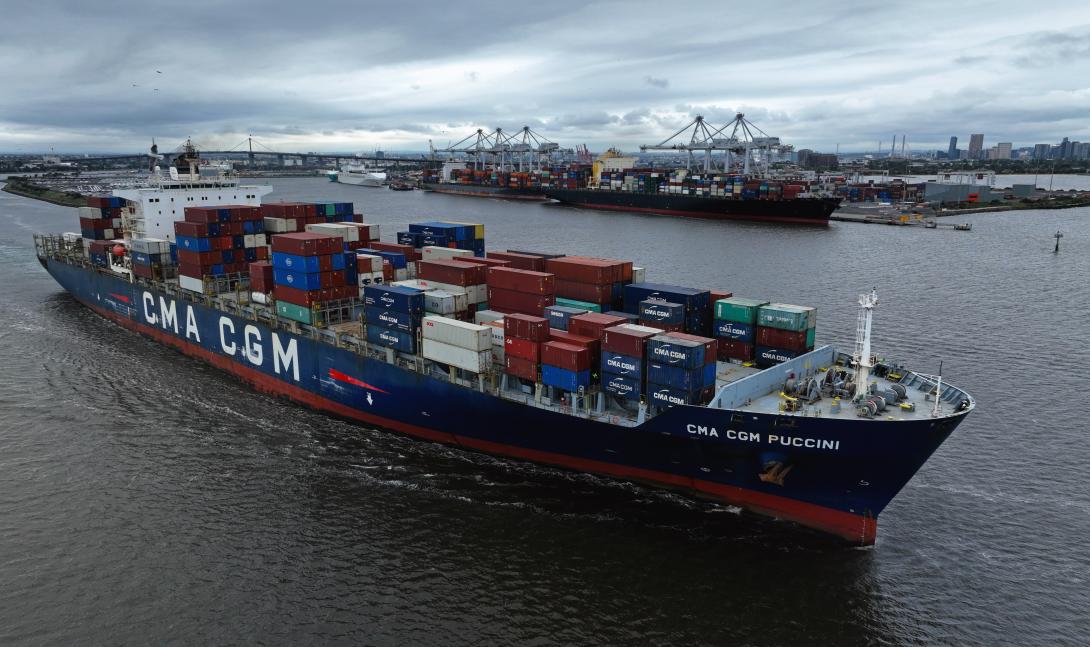
Source: Owen Foley
The following day, the ship was attended by an Australian Maritime Safety Authority (AMSA) surveyor to conduct, among other things, a port State control (PSC) inspection. As part of the PSC inspection, emergency operation of the steering was conducted with the surveyor in attendance in the steering gear room. The ship’s chief engineer, chief mate, electro‑technical officer and the third engineer were there to carry out or oversee the test.
The test included changeover of steering control from the navigation bridge (bridge) to the steering gear room followed by demonstration of local operation of the steering gear. The third engineer configured the steering machinery for local operation, including starting one steering gear pump and opening the bypass valve on the other pump (stopped). Control of the rudder was then demonstrated by manual operation of the running pump solenoid valve. Both pump systems were tested in local control. The steering tests were completed to the satisfaction of the surveyor.
Steering failure
The ship’s remaining stay at the berth was routine with nothing significant or unusual reported. At 0300 on 25 May 2023, the second mate on watch on the bridge called the engine control room (ECR) and gave one hour’s notice to ready the main engine for departure. The second mate then called the third mate and the deck cadet to assist with preparations for departure, including steering gear checks. The deck cadet was sent to the steering gear room to witness rudder movement and repeat its response to the third mate who operated the steering from the bridge steering console. At 0322, rudder operation to maximum angles (hard over on both sides) was checked using one, then the second pump, separately, and then both together. The steering gear was recorded to have been tested as required by regulations.
At 0346, the main engine was tested and the pilot boarded at 0350. The bow thruster was tested and, at 0354, the master-pilot exchange was conducted on the bridge. On the bridge for departure were the pilot, master, chief mate, deck cadet and an able seafarer at the helm. In the engine control room were the chief engineer, third engineer (the duty engineer) and the electro-technical officer.
Weather conditions for the departure were clear skies and good visibility with winds from the north‑north-east at force 4.[2] The tide was flooding, with high water expected at 0545. Just after 0405, 2 tugs were made fast (one forward, one aft) and by 0418 all mooring lines had been let go. CMA CGM Puccini was then manoeuvred out of Swanson Dock, through a 60° turn to starboard and into the Yarra River[3] (Figure 2).
During the turn to leave Swanson Dock, the master and chief mate noticed that the rudder response appeared sluggish, as if only one steering pump was running (both pumps were operating). Neither raised their observations with each other, or the pilot, and there were no alarms to indicate a pump had stopped or other abnormal condition.
By 0436, the ship was moving along the channel in the river, both tugs had been dismissed and the main engine was increased to slow ahead. At 0442, the ship passed under the Westgate bridge, about 1 mile[4] downriver of Swanson Dock. The ship’s speed was 6.6 knots[5] with a rate of turn of 4° per minute to port. At 0443, the main engine speed was increased to half ahead[6] and more rudder ordered (port 10)[7] to increase the rate of turn. To maintain the turn rate, the pilot then gave helm orders (rudder) of port 5 (0443:34), followed by port 10 (0443:54).
Soon thereafter (0444:03), the pilot noticed that the rudder angle indicator was showing that the rudder was midships and repeated the earlier port 10 order. The able seafarer steering the ship by hand (helmsman) advised that the helm (steering wheel) was at port 10. This exchange drew the attention of the master and chief mate, who both verified that the helmsman had correctly followed the order.
The helmsman informed them that the rudder was not responding to the wheel. By that time, the chief mate had moved to the steering console to investigate and observed that the rudder moved to port 5 and then slowly to starboard 5. The ship, with its speed increasing and rate of turn diminishing, tracked toward the western edge of the channel and beacon 32. At the time, the ship’s speed was 7.7 knots, it was turning to port at 3° per minute and was 7 m to starboard of its planned track.[8]
Figure 2: CMA CGM Puccini’s track from Swanson Dock to Webb dock
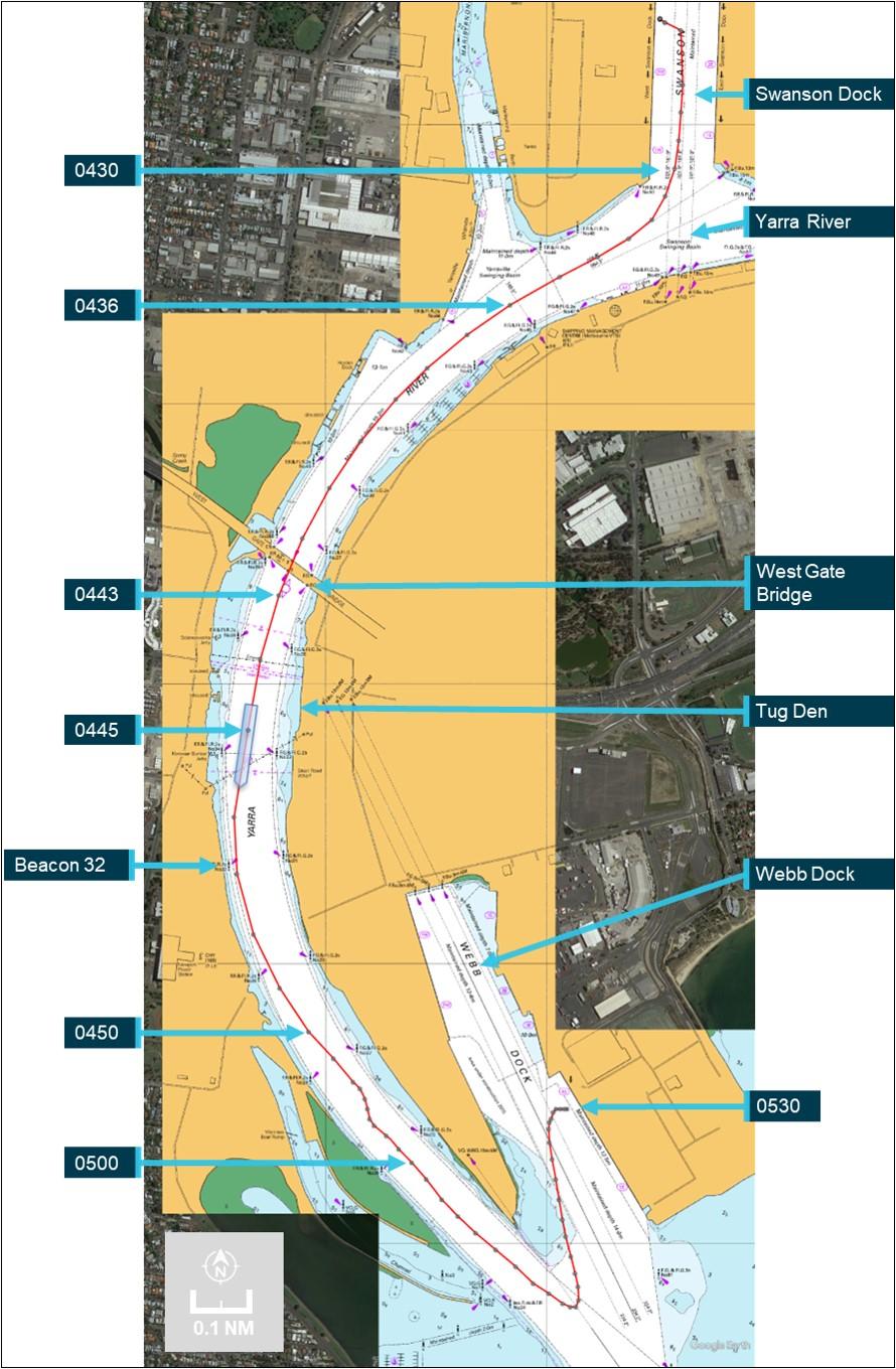
Position markers indicate location of ship’s main mast, about 181 m from the bow (atop the wheelhouse). Source: Australian Hydrographic Office, Google Earth, annotated by the ATSB
Further helm orders and helm movement indicated that the rudder was not responding. The master remained at the manoeuvring console and, after confirming with the pilot, reduced the main engine speed to slow ahead, and then (0444:50) to dead slow ahead. The master confirmed that the bow thruster was operational and suggested further slowing the ship (to less than 5 knots) to make the thruster effective.
At about this time, the master called the ECR and asked for the steering gear to be attended immediately. In response, the chief engineer called the electro-technical officer, who had returned to the accommodation, and directed them to go to the steering gear room. The electro-technical officer collected a radio and soon thereafter was informed by the master (via radio) that emergency steering was required.
Meanwhile, the chief mate and the helmsman went about fault finding and checked steering control modes, including non-follow-up (NFU).[9] Their attempts were unsuccessful and the rudder remained unresponsive to control inputs. At 0445, the pilot contacted Melbourne vessel traffic service (VTS) and reported that the ship had lost steering and requested immediate tug assistance. Both tugs that had been dismissed earlier were directed to return to the ship.[10]
The pilot then instructed the helmsman, using NFU, to put the rudder hard to port if and when possible. At 0445:26, the main engine was stopped. CMA CGM Puccini’s speed was 8 knots and it was turning to port at 1° per minute. The ship was now 26 m to starboard of track with its bow about 32 m from the 10 m depth contour (the edge of the navigable channel).
Shortly thereafter, the rudder was observed to move to 35° to port (wheel was hard to port). The main engine was restarted, and the bow thruster set full to port. At 0445:30, the ship’s rate of turn to port suddenly increased as its bow closed with the side of the channel. By 0445:44, the ship’s speed had reduced marginally (to 7.9 knots) and its swing to port had increased to 13° per minute, with the bow now less than 20 m from channel's edge. The pilot ordered the rudder midships and immediately after to starboard 20 to reduce the increasing swing to port with the aim of avoiding the ship’s stern closing and contacting the western bank or shoals (Figure 3).
At 0446:12, the ship was 58 m to starboard of the planned track with significant headway (7.7 knots) and turning rapidly to port (20° per minute) with the bow only about 12 m from the 10 m depth contour and shoal water. Hard starboard rudder and bow thruster full starboard were ordered and the rudder observed to move to about 20° to starboard. However, as CMA CGM Puccini was swinging to port, its stern was swinging in the opposite direction (to starboard) and contacted beacon 32. The impact resulted in damage to the beacon, which canted over about 20° from the vertical (cover photo). The ship’s side paintwork was scratched due to scraping against the beacon.
Following the contact, the helmsman advised that the wheel was hard starboard (as ordered) but the rudder angle was only 5° to starboard. At 0447, the ship’s speed had decreased to 7.2 knots and its swing to port had reduced (now 13° per minute). The ship was 67 m to starboard of track as the curve of its stern passed across the 10 m depth contour.
Meanwhile, both tug masters had been in contact with the pilot and the closer of the 2, SL Daintree, was instructed to make fast on the port shoulder. Svitzer Marysville was instructed to make fast aft through the centre lead. The ship’s speed was reducing (6.9 knots at 0447:26) and its turn rate was unchanged with the bow thruster kept full starboard to arrest the swing.
The master confirmed that steering control had not been restored. The ship’s bow was now in the middle of the channel and the stern clear of the channel’s edge. The engine was ordered dead slow astern at 0448:56, followed soon after by slow astern. The master ordered the rudder to be put midships and a series of astern engine movements reduced the ship’s speed to 4.5 knots.
Figure 3: CMA CGM Puccini’s track showing contact with Beacon 32
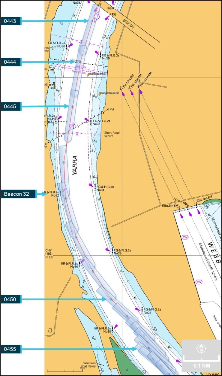
Source: Australian Hydrographic Office, Google Earth, annotated by the ATSB
At about 0451, the bow thruster was stopped and tug orders given to arrest CMA CGM Puccini’s headway. The ship had started swinging to starboard and at 0451 cleared the eastern side of the channel with its bow about 15 m from the channel edge. Headway had reduced to 2 knots and the ship continued to move away from the eastern bank, now turning to starboard at 3° per minute.
At 0454, with the ship temporarily stabilised along the centre of the channel, the pilot discussed moving the ship to Webb Dock (about 5 cables[11] downriver) with the ship’s bridge team and the tug masters. Once they had agreed on the proposed plan, the pilot advised VTS about the recovery plan.
Meanwhile, efforts to engage emergency steering locally from the steering gear room were ongoing with the electro-technical officer and the third engineer there. At 0456, they notified the bridge that the steering gear was being reconfigured for emergency steering.
By this time, the ship’s speed had decreased to about 1 knot and the 25-knot wind from the north‑north‑east was turning the ship to port. The pilot ordered dead slow ahead and, with the tugs assisting, began moving the ship towards Webb Dock. Shortly after, emergency steering was engaged and rudder orders given via the dedicated emergency telephone in the steering gear room.
At 0541, CMA CGM Puccini was made fast alongside Webb Dock East berth 4 without further incident. At the completion of movements, the electro-technical officer and third engineer reconfigured the steering from emergency to normal.
Inspections
Later that day various parties attended CMA CGM Puccini to inspect the ship’s steering gear. This included personnel from AMSA, the ship’s manager’s (CMA CGM), classification society (Bureau Veritas (BV)) and 2 independent service engineering companies to fault-find and test the steering gear. The ship was detained (by AMSA) as reasonably assumed as ‘being unseaworthy due to failure of steering and possible damage to the hull.’
An underwater hull examination by divers the following day, 26 May, found no hull damage. Additionally, the ship’s engineers inspected and tested the steering gear and systems and changed the hydraulic oil filters. Nothing abnormal was found.
Despite multiple, extensive inspections and tests by the ship’s engineers and the service engineers, the erratic behaviour of the steering gear could not be replicated and no fault was identified.
Later on 26 May, AMSA received confirmation from BV that the steering gear had been tested, no defect found and nor had there been any hull damage. Subsequently, AMSA released the ship from detention.
At 2028 that day, the ship was issued its port clearance and preparations were made to depart Melbourne the next morning.
Departure Melbourne
At 0630 on 27 May 2023, one hour’s notice was given to the engine room for departure and, at 0640, the steering gear was tested in bridge control without issue. At 0700, the pilot (the same pilot as during the incident) boarded. The master-pilot exchange was completed, and, among other things, a steering failure risk assessment prepared for this pilotage was discussed. Additional precautions prescribed by the Melbourne harbour master were in place and included in the risk assessment. These included having the electro-technical officer and an able seafarer standing by in the steering gear room for the pilotage.
CMA CGM Puccini’s unberthing and departure into Port Phillip Bay were completed without incident. Once sufficient sea room was available, the ship was taken out of the channel into open water in the bay, its speed increased to 16 knots and the steering tested with various rudder movements. The steering gear operated normally.
At 1150, the ship re-entered the channel to depart Melbourne. The pilotage continued without incident, the pilot disembarked at 1357 and the ship set course for Port Botany, New South Wales.
Melbourne to Brisbane
On 28 May, in preparation for arrival to Port Botany, and to meet Port Authority of New South Wales’ arrival requirements, CMA CGM Puccini’s crew tested the steering gear. The chief mate, duty mate, deck cadet, bosun and off-duty able seafarers were in the steering gear room. The master and duty able seafarer were on the bridge for the test.
These tests included changing over to emergency steering (local control). The chief mate reconfigured the steering machinery as previously shown by the third engineer. When an attempt to steer the ship was made, the steering began to behave erratically and did not respond exactly to the helm orders. At this time, the newly‑joined second engineer arrived to observe the tests. The engineer noticed that the system’s hydraulics were incorrectly configured and asked the chief mate to close the bypass valve of the (non-running) pump. Once the valve was closed, there were no further erratic rudder responses.
At 1912 that day, a pilot boarded. The pre-arrival declaration from the master to the Port Authority confirmed that the steering had been tested but made no mention of the Melbourne incident. The pilot had been made aware (informally) of the incident in Melbourne, though not of its nature, extent or resolution. Hence, during the master-pilot exchange, the pilot queried the master about the incident but received no additional information. The master, however, did inform the pilot that the steering gear room was being attended by the electro-technical officer and an able seafarer for the duration of the pilotage. With 2 tugs in attendance (the usual for such pilotages), the pilot conducted the ship into Port Botany. After it was berthed, the pilot submitted a report about the steering matter to the harbour master.
Subsequently, on 30 May, the ship departed Port Botany for Brisbane. The steering had been tested at 0450, with nothing abnormal observed, and at 0545 the (same) pilot boarded. As a result of the pilot’s earlier incident report, an additional tug was assigned for departure. The electro‑technical officer and an able seafarer stood by in the steering gear room during the pilotage, which was completed without incident and, at 0645, the pilot disembarked.
At 0630 on 1 June, the ship’s steering gear was tested before entering Brisbane and functioned normally. The electro-technical officer and an able seafarer again stood by in the steering gear room during the pilotage and the ship berthed without incident at 1318.
On 2 June, ATSB investigators attended the ship and as part of this investigation, inspected the steering gear and conducted tests and simulations. No defects with the steering gear systems were found.
CMA CGM Puccini departed Brisbane on 4 June without incident.
Context
CMA CGM Puccini
CMA CGM Puccini was built by Samsung Heavy Industries (Korea) in 2004. At the time of the incident, it was owned by CMA CGM, France, managed and operated by CMA CGM International Shipping, Singapore, and classed with Bureau Veritas (BV). The ship’s trading in recent years has regularly included Australian ports of call.
The ship had a length overall of 277.30 m and a beam of 40.0m. It had a gross tonnage[12] of 65,730 and deadweight[13] of 73,234 DWT at a draught of 14.526 m. It could carry 5,782 TEU including 3,168 on deck and 500 refrigerated containers. On arrival into Melbourne the ship was carrying 4,337 TEU (2,860 containers) and on departure 3,552 TEU (2,354 containers).
The ship was fitted with a Hyundai MAN B&W 10K98 MC-C main engine that delivered 57,075 kW through a fixed‑pitch, four-bladed, 8.70 m diameter, right-handed propeller. The ship’s manoeuvring speeds (in loaded condition) were 6.2 knots at dead slow ahead, 8.3 knots at slow ahead and 12 knots at half ahead.
CMA CGM Puccini was fitted with a semi-balanced, spade type rudder with an effective area of 52.18 m² and standard maximum working angles of 35° to port and starboard (see the section titled Steering gear for further details). The ship was also fitted with a 2,000 kW bow thruster. The bow thruster became ineffective once the ship’s speed increased to 5 knots.
Crew
CMA CGM Puccini had a multinational crew of 23 Romanian, Sri Lankan and Malaysian nationals. All were appropriately qualified and endorsed for the positions they held.
The deck department consisted of the master, 4 deck officers (chief mate, second mate and 2 third mates) and a deck cadet. The chief mate did not keep a navigation watch. The deck crew consisted of the bosun, 3 able seafarers and an ordinary seafarer.
The engineering department consisted of the chief engineer, 3 engineers (second, third and fourth engineers), an electro-technical officer, a reefer engineer (for refrigerated containers) and a refrigeration assistant, plus a fitter and 2 oilers.
The master was sailing with a Romanian master’s qualification issued in 2023. They had joined the ship for this posting in February 2023.
The chief mate was sailing with a Romanian chief mate’s qualification issued in 2018. Prior to joining CMA CGM Puccini as chief mate in 2021, and since 2016, they had sailed as second mate in the CMA CGM fleet of container ships. This was their fourth contract as chief mate on CMA CGM Puccini and they had joined in February 2023.
The chief engineer was an experienced seafarer with many years in the position. At the time of the incident, they were sailing with a Romanian chief engineer qualification issued in 2017. Recent experience, since 2017, had all been on CMA CGM container ships. This was the chief engineer’s first time on CMA CGM Puccini after their previous 4-month posting as chief engineer of the sistership CMA CGM Chopin and they had joined CMA CGM Puccini in April 2023.
The second engineer was sailing with a Romanian chief engineer qualification issued in 2016. They had sailed on 4 ships since 2021, all as second engineer, after spending time ashore in a CMA CGM shore management role. Recent experience was all on CMA CGM container ships. The second engineer joined in Melbourne, 2 days before the incident.
The third engineer was sailing with Sri Lankan engineering qualifications issued in 2017. Since 2017, the third engineer had sailed on 7 ships, all as third engineer. They joined the CMA CGM container ship fleet in 2018. This was the third engineer’s first posting to CMA CGM Puccini with a previous posting (9 months) as third engineer in its sistership CMA CGM Bellini. The third engineer joined CMA CGM Puccini in March 2023.
The electro-technical officer had Romanian qualifications as an electrical officer obtained in 2016. This was their tenth ship (all container ships) since 2016. The electro-technical officer joined CMA CGM Puccini in February 2023 and had had a previous 5‑month posting to the ship in 2022.
Pilot
The pilot assigned to CMA CGM Puccini first went to sea as a deck cadet in 2002 and went on to obtain an Australian master class 1 certificate in 2012. After working in several positions at sea and ashore, the pilot commenced training as a Melbourne marine pilot, with Auriga Pilots, in 2018. They obtained an unlimited pilot’s licence in 2022 and had piloted CMA CGM Puccini, and its sisterships, on multiple occasions, including with the master at the time of the incident.
Steering gear
The normal method of steering a ship is from the bridge (that is, remotely). The generally accepted use of the term ‘emergency steering’ refers to the method of steering when remote steering from the bridge fails. On most ships, including CMA CGM Puccini, emergency steering is local steering from the steering gear room.
Description
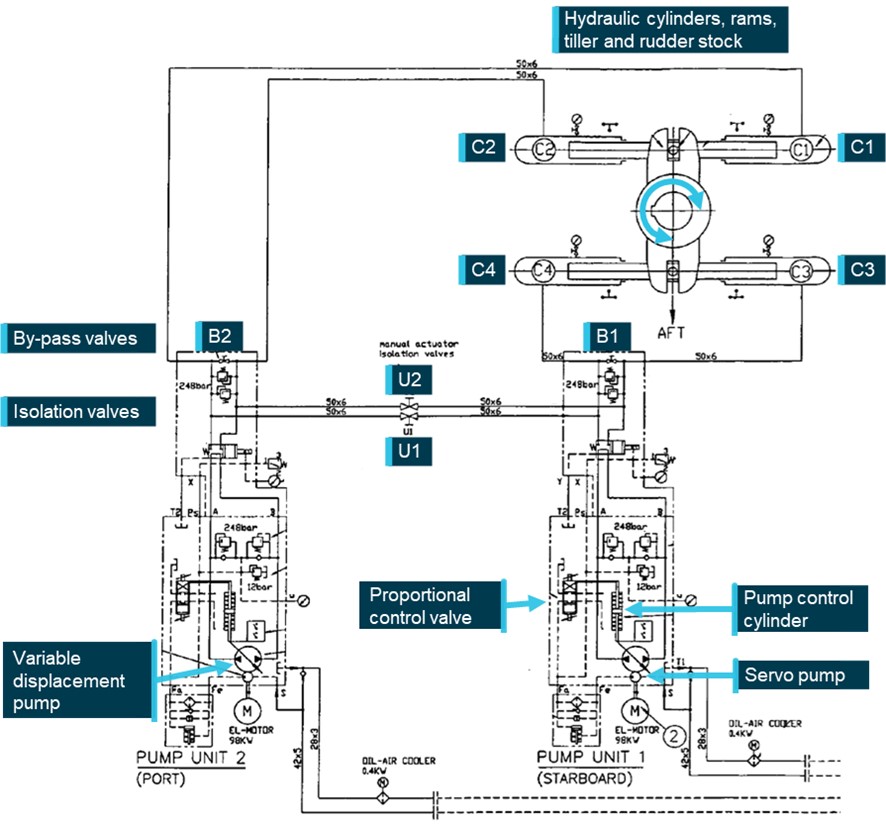
CMA CGM Puccini was fitted with a Samsung-Hatlapa,[14] Teleram type R4ST 700, 2-ram (300 mm diameter), 4-cylinder Rapson-slide electro-hydraulic steering gear with 2 identical power units. Rudder angle limits were set at 35° by electrical limit switches and 37° by mechanical stops.
The steering gear comprised 2 identical constant‑speed electric motors driving variable delivery piston pumps in a closed-loop hydraulic system (system relief valve setting was 250 kg/cm²). Each pump supplied bi-directional, infinitely‑variable hydraulic oil flow to/from 2 cylinders connected to a ram. This ram was then attached through a Rapson‑slide mechanism to the tiller arm, rudder stock and rudder. Pump flow rate and direction were controlled via a spring-loaded, self-centring pump control cylinder mounted as part of the pump housing, connected to the pump swashplate mechanism.
Each electric motor also drove a smaller, hydraulic auxiliary servo pump which provided 25 kg/cm² control oil to the machinery. An electric solenoid‑operated hydraulic proportional control valve altered control oil flow to/from either side of the pump control cylinder to adjust the swashplate angle and oil flow rate and direction at the pump, as required. The rudder position was thereby changed by altering the rate and direction of oil flow to or from the cylinders connected to the tiller (Figure 4).
Each pump was separated from the hydraulic circuit via an electrically‑operated automatic pump isolation valve. Under normal conditions, when the pump motor started, its automatic pump isolation valve operated and connected the pump oil lines to the greater hydraulic circuit. Both pump proportional control valves received signals from the control system (signal from the bridge steering console), which allowed both pumps to be operated in parallel supplying pressurised oil to the system. With 2 pumps running the system would respond more quickly.
Figure 4: Steering gear hydraulic diagram
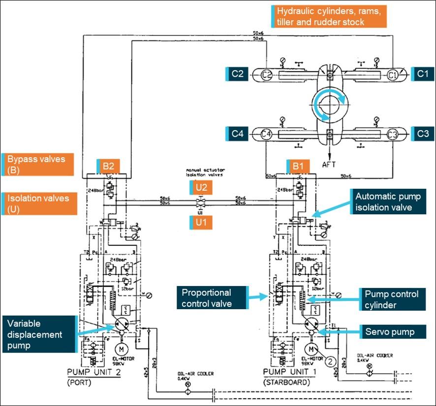
Source: CMA CGM, annotated by the ATSB
Other ancillary components, such as oil expansion and storage tanks, oil filtration and cooling systems and electrical control, switching and monitoring completed the steering machinery.
Hydraulic pump unit 1 (starboard) was connected to cylinders C3 and C4 and pump unit 2 (port) to cylinders C1 and C2. Manually operated valves were fitted in the hydraulics systems to allow flexible operation of the system:
- pump bypass valves (B1 and B2) provided connection between individual pump suction and discharge lines to allow oil flow between cylinders, across a (non-running) pump. The valves were painted red and had their valve handles fitted.
- isolation valves (designated U1 and U2) separated the 2 hydraulic circuits. The valves were painted red and the valve handles had been removed and were located adjacent to the steering gear in an area marked ‘Tools for emergency steering’. The valve handles were to be refitted and the valves operated as part of the ship ‘Steering gear failure with oil leakage’ procedure.
Brass plaques with operating instructions, a block diagram of the system and the valve position status matrix were permanently mounted adjacent to the steering machinery. A copy of CMA CGM Puccini’s steering gear failure procedure was mounted and available at the steering gear.
Normal operation
During normal operation either one or both pumps were running, supplying all 4 cylinders. Isolation valves (U1 and U2) were open, pump bypass valves (B1 and B2) were closed (Figure 5).
Figure 5: Single pump, 4-cylinder, normal operation of steering, to port and starboard
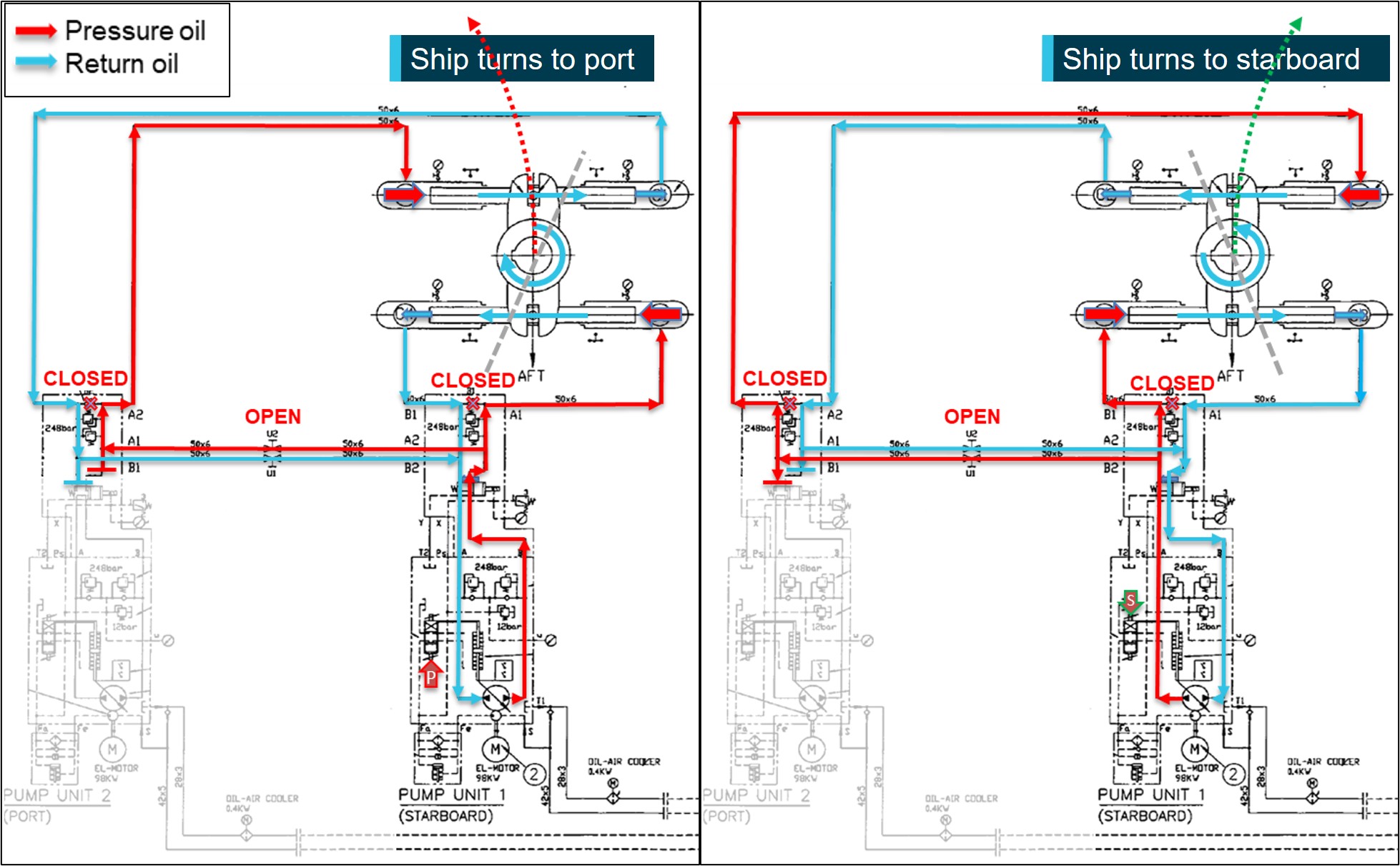
Single pump (#1) operation shown; diagram is similar for pump 2. Isolation valves (U1, U2) open, pump bypass valves (B1, B2) closed. Signal is received into the proportional valve altering the flow rate and direction of oil at the pump. System response will be improved (faster) with second pump operating in parallel. Source: CMA CGM, annotated by the ATSB
If the second pump was started, the run signal to the electric motor also activated the automatic pump isolation valve. This connected the second pump’s oil lines to the active hydraulic circuit. The control signal (from the bridge) now adjusted both pumps in parallel and the second pump boosted oil flow to the pressure line, increasing the speed of operation of the system.
Operation with one hydraulic circuit isolated
It was possible to separate the 2 hydraulic circuits and operate on one circuit (and pump) alone. In this case, the isolation valves were to be closed and the bypass valve on the non‑running pump was to be opened (Figure 6). This mode of operation was referred to in the shipboard procedures in relation to steering gear failure with oil leakage in one of the circuits.
Figure 6: Port rudder using pump 1 with hydraulic system 2 (pump 2, cylinders C1 and C2) isolated
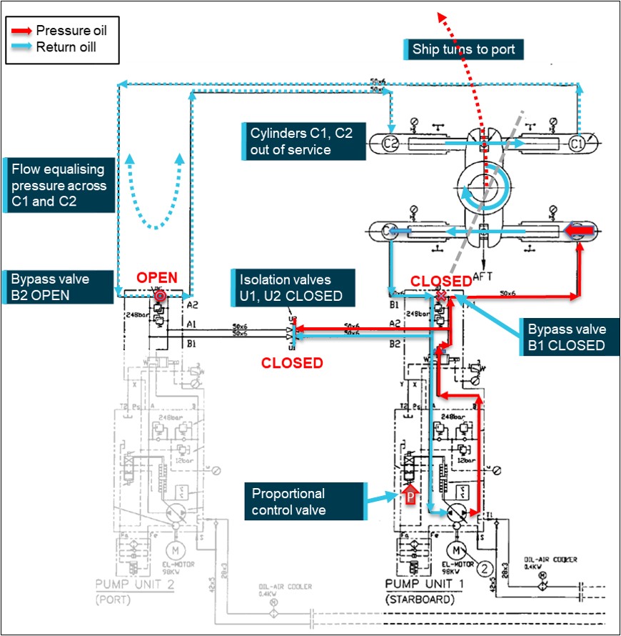
Hydraulic system 2 out of service, isolation valves (U1, U2) closed, pump 2 isolated, pump 2 bypass valve (B2) open to allow oil flow between cylinders C1 and C2 and prevent hydraulic locking. Source: CMA CGM, annotated by the ATSB
Remote operation
The manufacturer (Samsung-Hatlapa) provided machinery and equipment to design scope and, as a minimum, supplied an electro-hydraulic steering gear which could be operated locally from the steering gear room. Capability was provided for interfacing with a variety of possible remote operating systems available from the manufacturer or other third party equipment providers.
CMA CGM Puccini was fitted with a Sperry Marine, Navipilot 4000 heading control system for remote steering control from the steering console on the bridge. In remote operation, rudder position (steering) signals were sent from the console to the running pump(s) proportional control valve(s). The signal operated the valve(s) and adjusted the rudder position. Rudder position was monitored by sensors connected to the tiller boss (attached to the rudder stock).
Three modes of remote operation were available:
- Auto: The user input the desired heading, rate of turn or turn radius into the Navipilot control and display unit at the steering console. The software then adjusted the rudder angle to achieve the set value. Signals were sent to the solenoids of the proportional control valve to move the rudder in the desired direction. Feedback of rudder position from one of the independent rudder angle sensors was compared to the desired value. The control system compared the desired and actual values and adjusted the rudder angle until the difference between them (the error) reduced to zero.
- Follow-up (FU): Follow-up steering mode is closed-loop, hand steering from the bridge steering console. The desired rudder angle is set by the operator (e.g. helmsman) adjusting the position of the ship’s wheel. This set value is compared to the actual rudder position taken from the rudder angle sensor and the error used to generate a control signal to the appropriate solenoid of the proportional valve. The rudder is moved until the error is reduced to zero and the rudder position the same as that set at the steering wheel.
- Non-follow-up (NFU): This is open-loop, manual steering from the steering console. The operator uses a lever to manually send signals to the proportional valve to turn the rudder in the direction desired. When the lever is returned to the neutral position the signal stops, as does the rudder movement. The control loop is closed by the operator visually comparing the rudder position displayed on the rudder angle indicator with that desired and using the lever to move the rudder accordingly. On board CMA CGM Puccini, NFU control was available from the steering console, the manoeuvring panel, and both bridge wings.
Local control
As is common, local control of the steering was from the steering gear room. To change from remote to local control, the rudder position feedback signal to the steering console had to be isolated. This was achieved by selecting NFU on the steering console on the bridge.
Once the feedback signal was isolated, the steering could be controlled by manually operating the proportional control valve on the running hydraulic pump. Rudder position was displayed on a graduated scale by a pointer connected to the rudder. The operator manipulated the appropriate solenoid valve of the proportional valve until the desired rudder angle was achieved. A tool to assist operation of the solenoid valves was mounted in the area marked ‘Tools for emergency steering’, adjacent to the steering machinery.
It was normal to use one pump for local control, but the system did not require the second pump to be stopped to operate. In that case, the second variable delivery pump remained in the neutral position, with no throughput, and did not affect operation of the system.
Manufacturer instructions
The steering gear manufacturer’s ‘Instruction manual for steering gear’ described technical, operation, maintenance and spare parts requirements for the machinery.
The manual provided instructions for:
1. Standard operation, which covered:
a. operation from the bridge – instruction to change running pump every 24 hours
b. operation from the steering gear compartment – instructions to establish contact with the bridge, disconnect the solenoid valves from the autopilot and operate solenoid valves manually as required.
2. Emergency operation, which included instructions to:
a. Reduce ship speed to less than 70%
b. Choose one pump system for use
c. Configure system valves as per the valve position plate
d. Manually operate proportional solenoid valve as appropriate.
The emergency operation instructions also include actions to take for system alarms: pump alarm on the bridge, hydraulic locking and low oil level.
The valve position plate (Figure 7) provided a table displaying pump operation and valve positions (bypass and isolating valves) for 3 operating modes:
- Standard operation with 4 cylinders and one or both pumps
- Emergency operation with pump 1 only
- Emergency operation with pump 2 only.
A brass instruction plate and a separate brass valve position plate were attached to the steering machinery. The instruction plate was separated into 3 sections:
- at the top, a block diagram of the steering gear
- below this, operating instructions for standard and emergency operation as described above
- at the bottom, a copy of the table from the valve position plate.
Shipboard procedures
As part of mandatory safety management requirements,[15] the CMA CGM Group fleet operated an integrated management system (IMS) for operations across its fleet and related shore operations. The IMS included more than 500 procedures (cards) for common fleetwide tasks in various ‘manuals’. Ship‑specific cards were managed on board an individual ship with approval from shore management. The system on board CMA CGM Puccini included about 70 ship-specific cards of which the ones key to steering are summarised below.
- The bridge ‘departure checklist’ (Bridge manual card Bridge-051) was to be completed before departure and its completion recorded in the bridge logbook. The checklist included verifying the steering gear, including means of communication to the steering gear room, was operational. This required testing each pump and system operated individually and then together. The test required all pumps and rudder angle indicators to be checked while moving the rudder to hard over on both sides, as required by regulations.
- The navigation ‘preparation for arrival checklist’ (Bridge manual card Bridge-070A) required both steering systems operating with manual (follow-up) steering engaged. Its completion was to be recorded in the bridge logbook, with any items in the checklist not completed to be listed.
- The ‘steering gear failure checklist’ (Emergency manual card Emcy-030) detailed the checks to be followed in the event of steering failure. Immediate actions included engaging hand steering (manual) and starting the second steering motor. Where necessary, further actions included mustering the crew and transferring to local steering control.
- The ship-specific ‘steering gear and auto pilot control’ (Bridge-550 card) procedure related to using the bridge steering column controls fitted in CMA CGM Puccini and made passing references to operating the steering machinery. The procedure referred to FU as hand steering, and, when referring to NFU, stated ‘This position must be selected for steering from Steering gear room (Em’cy steering)’[16]
- The ship-specific ‘steering gear failure’ procedure (Engine-650) outlined, with illustrations, the actions to take in 2 different scenarios:
- Control from the steering gear room
This section detailed the changeover from remote steering to local control. NFU was to be selected on the steering console and the preferred steering motor selected. An explanation, with photographs, illustrated how to access and manipulate the solenoids for the steering pump proportional control valve to operate the steering. Requirements to verify communications using the emergency, sound-powered telephone and checking that the local gyrocompass repeater was synchronised with the one on the bridge were also included. - Steering gear failure with oil leakage
This section outlined the actions in the event of an oil leakage and the steering gear was to be operated using only one steering system and 2 cylinders. Users were advised to follow the maker’s instructions posted in the steering gear room. The procedure then stepped through the reconfiguration (manipulating the bypass and isolating valves as described in the Steering gear section above) of the machinery to steer the ship. Rudder movement was via manual manipulation of the proportional control valve solenoids as in local control. This procedure followed the valve reconfiguration as described by the steering gear manufacturer’s emergency operation with one pump procedure shown on the valve position plate.
Copies of the ‘steering gear failure’ card were posted adjacent to the bridge steering console and in the steering gear room.
CMA CGM documents confirmed that the ship‑specific steering gear failure procedure (Engine‑650) was contained in the company IMS index and used by ships fleetwide. Examples provided (from ships other than CMA CGM Puccini) contained similar language and detail to that outlined above. According to CMA CGM, this procedure met SOLAS[17] requirements and was to be displayed on the navigation bridge and in the steering compartment, as required.
- SOLAS required 3-monthly steering drills[18] and these were completed on board as required. The steering drills included testing steering control from the steering gear compartment, verifying the communications procedure with the bridge and verifying operation of alternative power supplies, as required by the regulation. The ‘Emcy-006 drill report form’ was to be completed with details of the drill conducted. The most recent such drill before this incident was recorded in March 2023, with the drill described as having been conducted as per the company Emcy-030 checklist and the SOLAS regulation. The steering gear failure (Engine‑650) procedure was explained by the chief mate and electro-technical officer. The third engineer was also present for this drill.
CMA CGM advised that ‘steering gear failure’ was the term officially used in the IMS and fleetwide. Other terms such as ‘emergency, local, hand or manual steering’ were not defined in company procedures.
On board steering procedural knowledge
Following the incident, the ATSB interviewed crewmembers to determine their understanding of the steering system. Interviews were conducted while the ship was alongside in Brisbane, 8 days after the incident in Melbourne.
The chief engineer described normal and emergency operation of the steering gear, including being able to describe the valves to be manipulated and the need to fit valve handles to the isolation valves. The chief engineer was present during the PSC inspection and recalled operating the steering gear locally, but did not note any operation of the manual valves.
The chief mate learned how to configure the steering gear for emergency steering from the third engineer. That is, with the bridge steering console mode set to NFU, in the steering gear compartment the non-running pump bypass valve was to be opened, and rudder position adjusted by manually operating the solenoids of the proportional control valve on the running pump. The chief mate applied this knowledge when conducting steering tests prior to arrival into Port Botany.
The electro-technical officer described having a general understanding of the steering gear operation, with a focus on the electrical component. Their understanding of the configuration of the machinery for emergency control was similar to that of the third engineer. They described deferring to the third engineer for the hydraulic system changes when reconfiguring the steering to ‘emergency’ control during the incident.
The third engineer described their understanding of steering gear operation. When asked to describe how to achieve emergency steering, the third engineer indicated that they followed the valve position plate as fixed to the steering gear and shown in the steering gear instruction manual (Figure 7). The third engineer described how, as per this plate, ‘emergency’ operation required one pump to be isolated and its bypass valve to be opened. Following on from this, with the bridge steering console mode in NFU, the rudder could be moved by manually operating the solenoids of the proportional control valve on the running hydraulic pump.
This was the procedure followed by the third engineer when reconfiguring the steering gear for emergency steering during the incident. However, the third engineer could not then explain why the isolating valves, shown in the valve position table to be closed for this ‘emergency’ mode of operation, would not be operated.
Figure 7: Steering gear manufacturer's valve position plate
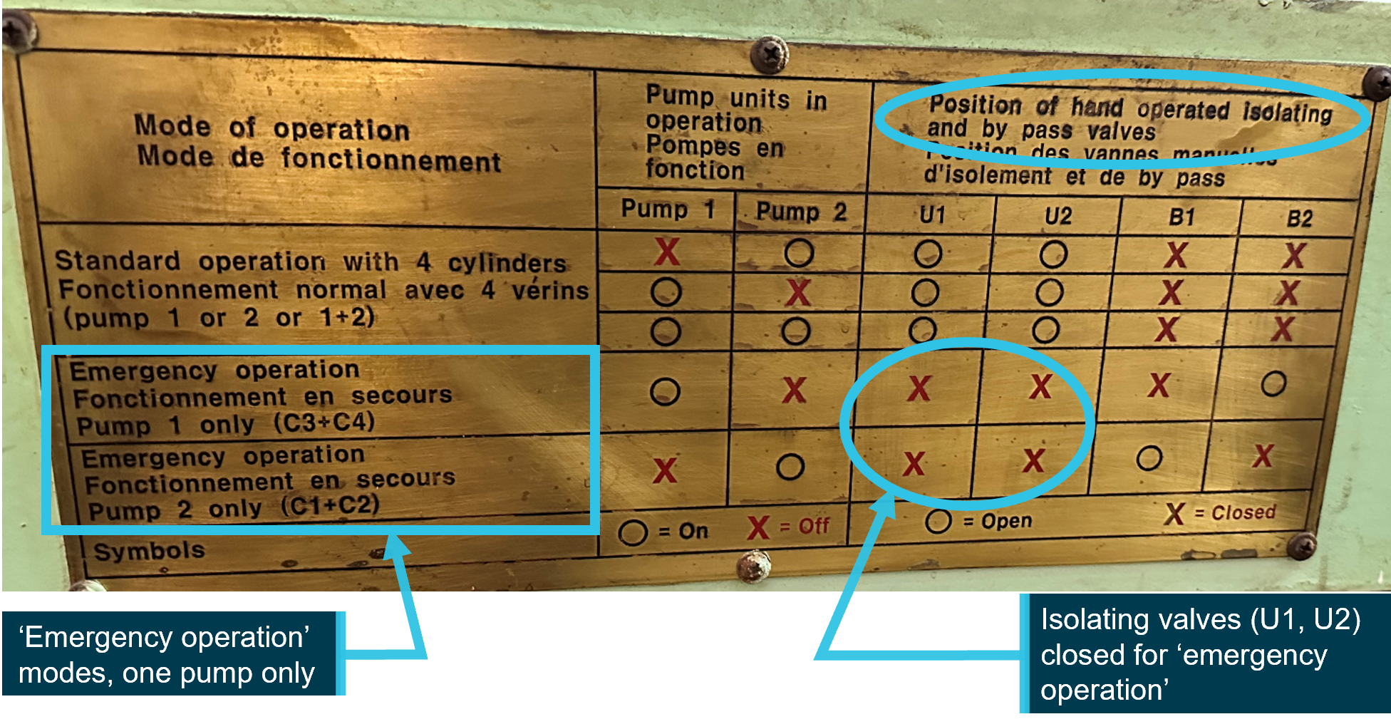
Source: CMA CGM, annotated by the ATSB
The chief mate, the electro-technical officer and the third engineer had all been present at the most recent steering gear drill.
While all persons interviewed showed some familiarity with how the steering gear operated, remotely and locally, none, including several senior officers, were able to accurately describe how the system operated. This was particularly so for steering from the steering gear room and relating to the need or otherwise for manual valve operation. This lack of knowledge was supported by the actions taken in relation to this incident and indicated that the depth of understanding was not as thorough as required.
International requirements
Steering gear regulations
SOLAS Chapter V, Regulation 26 described requirements for steering gear testing and drills. This regulation required the following:
- A pre-departure steering check and test by ship’s crew. This was to include machinery, system and control tests, a visual inspection of the steering gear, full movement tests and communications checks with the bridge.
- Simple operating instructions showing changeover procedures for remote steering gear control systems and steering gear power units (steering motor and pump etc) to be permanently displayed on the navigation bridge and in the steering gear room.
- All ships' officers concerned with the operation and/or maintenance of steering gear to be familiar with the operation of the steering systems fitted on the ship and with the procedures for changing from one system to another.
- Steering drills to be conducted at least every 3 months, as described above.
SOLAS Chapter II-1, Regulation 29 sets steering gear requirements such as rudder angle limits and speed of operation.
Training standards
The STCW code[19] sets the standards of competence for seafarers internationally. In relation to steering gear:
- Part A, Chapter II outlines standards regarding the master and deck department including:
- Section A-II/1 requires officers in charge of a navigational watch to demonstrate competence in steering control systems, operational procedures and changeover between manual and automatic modes and to manoeuvre the ship within safe steering system limits.
- Section A-II/2 requires masters and chief mates to have competence in responding to navigational emergencies with knowledge, understanding and proficiency in emergency steering through practical instruction, in-service experience and practical drills in emergency procedures.
- Part A, Chapter III sets standards regarding the engine department, including having demonstrated competence in operating and maintaining steering gear systems.
Post-incident steering gear tests
ATSB
Following initial investigation and analysis, ATSB investigators attended CMA CGM Puccini when it next called at Melbourne in July 2023 and tested the steering gear, including with one pump bypass valve open. With the bypass valve open, the rudder was moved through its full range of movement including from hard port to hard starboard and back. The steering was observed to operate as required and expected, and within the time required by the regulations.
Steering gear manufacturer
CMA CGM assessment of the incident and possible causes agreed with analyses completed and conclusions reached by the ATSB, including results from the post-incident tests outlined above. CMA CGM also commissioned the steering gear manufacturer to conduct further independent tests. The manufacturer’s tests identified that, with one bypass valve open:
- at low ship speeds (below about 8 knots), and low speed of water over the rudder, the hydrodynamic forces acting on the rudder (including the force as the rudder is moved and greater rudder surface area is exposed to the flow of water) did not affect steering gear operation
- at higher ship speeds (above about 8 knots) and increased water flow over the rudder, the hydrodynamic forces overcame the hydraulic forces and the steering gear would not operate correctly.
On this basis, CMA CGM concluded that the bypass valve was probably left open following testing for the PSC inspection.
Safety analysis
Introduction
In the early hours of 25 May 2023, the container ship CMA CGM Puccini was departing the port of Melbourne under the conduct of a harbour pilot. As the ship continued downriver, main engine power was increased and the rudder used to remain in the centre of the channel. Just after 0444, the bridge team noticed that the rudder was not responding exactly to the helm ordered. The ship turned wide in the channel as attempts were made to verify and restore steering. At about 0447, the ship closed on the western edge of the channel and contacted navigation beacon 32. The ship was then slowed and returned towards the middle of the channel. By 0454, it was stabilised in the channel with tug assistance and then conducted to nearby Webb Dock. The ship suffered minor hull paint damage and beacon 32 was significantly damaged.
The following analysis examines the events, actions and conditions leading up to and following the contact, particularly in regard to steering gear operating procedures and guidance. The analysis also considers the risks associated with ambiguities arising from steering terminology in common (industry) use and that used within the ship and the CMA CGM fleet.
|
Contributing factor During departure manoeuvring in the Yarra River, CMA CGM Puccini's rudder responded erratically and control of the steering was lost. As a result, the ship turned wide in the channel and contacted a navigational beacon. |
Loss of steering control
During manoeuvring on departure from Melbourne, as main engine speed was increased, and load on the rudder increased, control of the ship’s steering was lost. The only plausible explanation for the loss of steering control was that one of the steering pump bypass valves had been left open following recent testing (Figure 8).
|
Contributing factor Following steering tests conducted for port State control inspections on the day before the incident, one of the hydraulic pump bypass valves was left open. This resulted in the steering system hydraulics being incorrectly configured for normal operation. |
Figure 8: Steering gear hydraulics with both pumps running and one pump bypass valve open
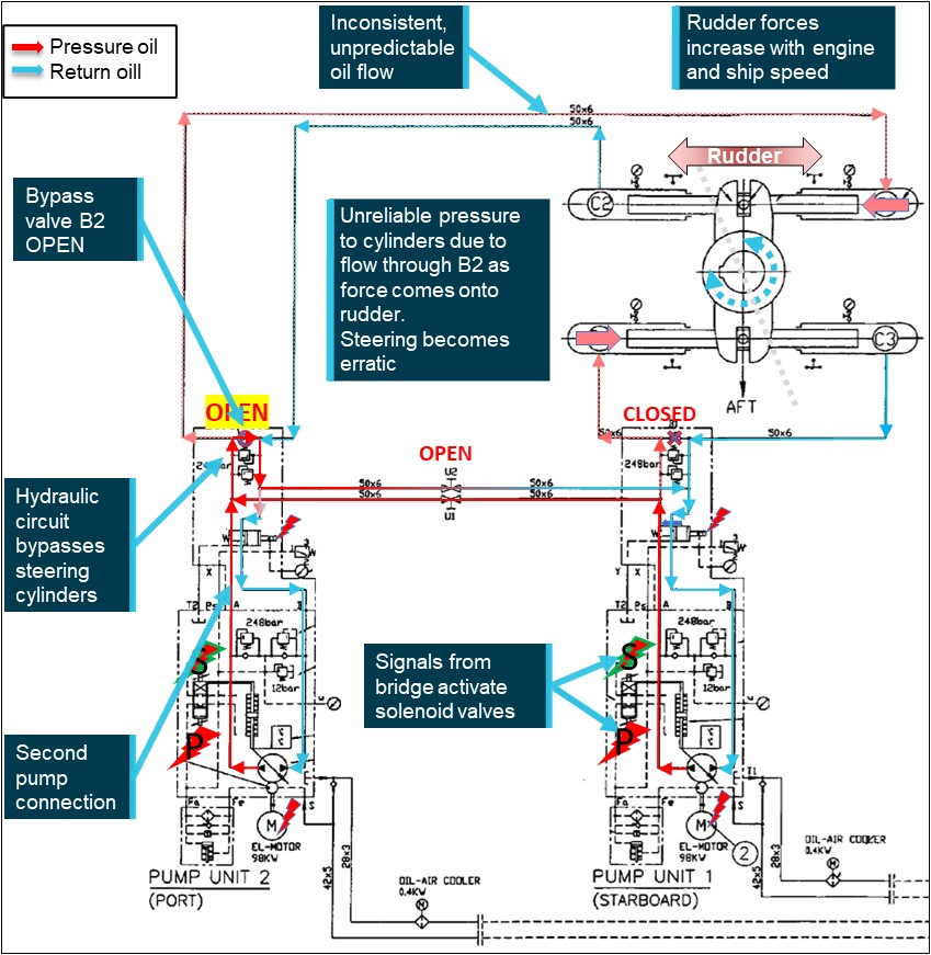
Source: CMA CGM, annotated by the ATSB
The steering pump bypass lines were about half the diameter of the system flow lines (Figure 9). The difference in pipe diameter allowed the majority of oil flow to pass to the hydraulic cylinders, with leakage through the open valve around the pump. With the ship alongside and with no water flow over the rudder, the load on the rudder was minimal and the hydraulics moved the rudder as expected and sufficiently well to pass the visual observations.
The open bypass valve would have slowed the speed of response but the system, with either, or both pumps running, was still capable of moving the rudder. This was probably the case during the PSC inspection, as well as during pre-departure steering checks.
Figure 9: Steering pump #2 bypass valve and system isolation valve arrangement
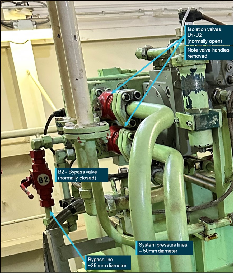
Source: CMA CGM, annotated by the ATSB
However, when the ship was underway and the main engine speed was increased, as the rudder was moved and a larger surface area was exposed to the water flow, the load on the rudder increased. At low speeds, the hydraulic system pressure and flow were sufficient to overcome the rudder loads. However, as the main engine was increased to half ahead, and the ship’s speed exceeded about 8 knots, the hydraulics were then adversely affected by the flow through the open bypass valve, leading to inconsistent, erratic response of the machinery. Control of the steering was subsequently lost, with the ship turning wide in the channel and making contact with the navigational beacon.
Following the incident, operational tests conducted with one bypass valve open and one (either) pump running confirmed that, while alongside, the steering system would move the rudder through its full range of operation, sufficient to pass visual inspection. The loss of positive response by the hydraulic system as the ship’s speed increased was confirmed by the steering gear manufacturer’s tests. The manufacturer’s report stated that:
…the sea water’s resistance does not affect steering gear under the low speed (below 8 knots) operation.
However, when increase speed above 8~10 knot then the hyd[raulic] pressure cannot keep pressure due to opened by-pass valve.
Therefore cannot operate steering gear properly.
|
Contributing factor The open bypass flow did not allow development of the required hydraulic system pressure to overcome the increased load on the rudder as the ship’s speed increased, resulting in erratic rudder response. |
Emergency steering
Seafarers are routinely warned that ‘any loss of steering may imperil the safety of the ship and life at sea’.[20] The critical importance of steering is highlighted in regulations[21] requiring:
- all ships' officers concerned with the operation and/or maintenance of steering gear to be familiar with the operation of the steering systems fitted on the ship and with the procedures for changing from one system to another. This includes the requirement for demonstrated competence by navigation officers in emergency steering, and change-over of steering control systems.
- regular and routine testing by the ship's crew of the ship's steering gear before departure. These checks and tests are often extended by ship procedures and/or port requirements to include pre‑arrival testing.
- emergency steering drills to be conducted at least once every 3 months and include direct control from the steering gear compartment and testing of alternative power supplies (emergency power).
- regular, routine and adequate inspection rounds of the steering machinery spaces.
Regulatory requirements are reflected in initial and continued seafarer training. These are also reinforced in ship and company procedures, requiring knowledge, proficiency and competence in steering system operation and maintenance, and all-of-crew training and emergency drills.
The term ‘emergency steering’ is widely used and accepted in the marine industry, and by regulators, as referring to steering from the steering gear room, or ‘local steering’. On board CMA CGM Puccini, in addition to its use in regulations, the term ‘emergency steering’ was found in procedures and in reference to emergency drills. However, following the incident, CMA CGM stated that ‘steering gear failure’ was the terminology used across its fleet’s documentation and other terms, such as ‘emergency steering’ were not used or defined. Consequently, no specific ‘emergency steering’ procedure, or definition, was used in ship‑specific and fleetwide procedures.
However, onboard CMA CGM Puccini, ‘emergency operation’ of the steering gear was used in the machinery manufacturer’s instruction manual. At interview, the third engineer, in explaining emergency steering, directed ATSB investigators to the valve position plate mounted on the steering gear and referenced in the steering gear instruction manual (Figure 7). The ‘emergency operation’ mode included in this instruction required reconfiguration of steering hydraulic system valves (pump bypass and system isolating valves) to separate the hydraulic systems and allow independent operation of each.
As a result of their understanding, the third engineer reconfigured the system valves when they manipulated the steering gear for ‘emergency steering’.
However, this understanding that ‘emergency steering’ required reconfiguring of system valves, was inconsistent with the general understanding that ‘emergency steering’ required the transfer of steering control from the navigation bridge to the steering gear compartment (local) (see the section titled Steering gear, local control for further information).
Regulations required that all relevant officers on board understood and were proficient in the requirements for and change-over to local operation of the steering gear. Such proficiency should have shown that to demonstrate steering from the steering compartment for the PSC inspection did not require the manipulation of steering hydraulics system valves. Similarly, subsequent reconfiguration of the hydraulics during the departure incident and before arrival to Port Botany was unnecessary.
The events, and the presence of senior officers at each, show that, collectively, the officers of CMA CGM Puccini did not have the required proficiency with steering gear operation and changer-over procedures. This had not been corrected by shipboard procedures or during routine shipboard operations including demonstration during steering gear emergency drills.
|
Contributing factor The responsible officers on board CMA CGM Puccini had an incomplete understanding of how the steering gear operated. This resulted in the incorrect configuration of the steering system hydraulics and erratic response of the rudder on multiple occasions. |
CMA CGM fleetwide steering gear guidance
The ship-specific steering gear failure procedure was used by all ships within the CMA CGM fleet. Further, commonly used steering terms, including ‘emergency steering’, were not defined within the company and the official term used was ‘steering gear failure’. The investigation found that, on board CMA CGM Puccini, there was a misunderstanding between the requirements for changeover of steering control from the navigation bridge (normal or remote steering) to the steering gear compartment (emergency or local steering) with the requirements for operation of the steering gear with oil leakage.
This misunderstanding manifested itself in the unnecessary reconfiguring of the steering system hydraulics when requested to demonstrate or change to local (emergency) steering. Furthermore, the possibility of such a misunderstanding was not restricted to CMA CGM Puccini as fleetwide procedures for steering gear failure contained similar language and detail and the terms used (and not used) were not explained. The use of multiple terms when referring to differing steering modes and operations in various procedures was ambiguous and confusing.
Following the incident, CMA CGM shared details of the incident with all ships in its fleet and then, in 2024, an article was published in the CMA CGM Group monthly QSSE (Quality Safety Security and Environment Management) report. This article was directed to Designated Persons Ashore (DPA) and briefly outlined the incident and the likely misconfiguration of the pump bypass valve as a cause. The article stated:
Based on…IMS Specific Card Engine-650 (Steering Gear Failure Procedure), the operation procedure during steering gear failure has been clearly defined. Please follow instruction step by step during each testing operation and ensure to reinstate valve’s setting back to normal operational condition.
However, the procedures in place and actions taken following the incident did not directly address the requirements for changing steering control from the navigation bridge to the steering gear room. Further, the terminology in use was not made clear and explained and, therefore, possible misunderstanding or confusion with common terms in use on board CMA CGM ships and within the industry remained.
|
Contributing factor The ship's managers' (CMA CGM) safety management system procedures and guidance for steering gear operation across its fleet were ambiguous and did not clarify the different terminology to those commonly used by the industry. This increased the risk of incorrect configuration of the steering gear, which occurred on board CMA CGM Puccini. (Safety issue) |
Findings
|
ATSB investigation report findings focus on safety factors (that is, events and conditions that increase risk). Safety factors include ‘contributing factors’ and ‘other factors that increased risk’ (that is, factors that did not meet the definition of a contributing factor for this occurrence but were still considered important to include in the report for the purpose of increasing awareness and enhancing safety). In addition ‘other findings’ may be included to provide important information about topics other than safety factors. Safety issues are highlighted in bold to emphasise their importance. A safety issue is a safety factor that (a) can reasonably be regarded as having the potential to adversely affect the safety of future operations, and (b) is a characteristic of an organisation or a system, rather than a characteristic of a specific individual, or characteristic of an operating environment at a specific point in time. These findings should not be read as apportioning blame or liability to any particular organisation or individual. |
From the evidence available, the following findings are made with respect to steering failure and contact with navigational beacon involving CMA CGM Puccini, port of Melbourne, Victoria on 25 May 2023.
Contributing factors
- During departure manoeuvring in the Yarra River, CMA CGM Puccini's rudder responded erratically and control of the steering was lost. As a result, the ship turned wide in the channel and contacted a navigational beacon.
- Following steering tests conducted for port State control inspections on the day before the incident, one of the hydraulic pump bypass valves was left open. This resulted in the steering system hydraulics being incorrectly configured for normal operation.
- The open bypass flow did not allow development of the required hydraulic system pressure to overcome the increased load on the rudder as the ship’s speed increased, resulting in erratic rudder response.
- The responsible officers on board CMA CGM Puccini had an incomplete understanding of how the steering gear operated. This resulted in the incorrect configuration of the steering system hydraulics and erratic response of the rudder on multiple occasions.
- The ship's managers' (CMA CGM) safety management system procedures and guidance for steering gear operation across its fleet were ambiguous and did not clarify the different terminology to those commonly used by the industry. This increased the risk of incorrect configuration of the steering gear, which occurred on board CMA CGM Puccini.(Safety issue)
Safety issues and actions
|
Central to the ATSB’s investigation of transport safety matters is the early identification of safety issues. The ATSB expects relevant organisations will address all safety issues an investigation identifies. Depending on the level of risk of a safety issue, the extent of corrective action taken by the relevant organisation(s), or the desirability of directing a broad safety message to the marine industry, the ATSB may issue a formal safety recommendation or safety advisory notice as part of the final report. All of the directly involved parties were provided with a draft report and invited to provide submissions. As part of that process, each organisation was asked to communicate what safety actions, if any, they had carried out or were planning to carry out in relation to each safety issue relevant to their organisation. Descriptions of each safety issue, and any associated safety recommendations, are detailed below. Click the link to read the full safety issue description, including the issue status and any safety action/s taken. Safety issues and actions are updated on this website when safety issue owners provide further information concerning the implementation of safety action. |
CMA CGM fleetwide steering system guidance
Safety issue number: MO-2023-002-SI-01
Safety issue description: The ship's managers' (CMA CGM) safety management system procedures and guidance for steering gear operation across its fleet were ambiguous and did not clarify the different terminology to those commonly used by the industry. This increased the risk of incorrect configuration of the steering gear, which occurred on board CMA CGM Puccini.
Safety action not associated with an identified safety issue
| Whether or not the ATSB identifies safety issues in the course of an investigation, relevant organisations may proactively initiate safety action in order to reduce their safety risk. The ATSB has been advised of the following proactive safety action in response to this occurrence. |
Additional safety action by Ports Victoria (port of Melbourne)
Following this incident, towage requirements under Harbour Master’s Directions for the port of Melbourne were strengthened so that all SOLAS commercial vessels transiting the Yarra River do so with harbour tugs in attendance.
In addition to updated towage requirements, specific directions were added for ships which experience a main engine or steering failure.
Glossary
| AMSA | Australian Maritime Safety Authority |
| DPA | The International Safety Management (ISM) Code requires a ship’s managers to have a Designated Person Ashore (DPA) who should aim to ensure the ship’s safe operation and provide a link between all those on board and the highest level of management ashore. |
| DWT | Deadweight tonnage is a measure of how much weight a ship can carry including cargo, fuel, ballast, fresh water, crew, passengers, and provisions. It is the difference between the displacement and the mass of empty vessel (lightweight) at any given draught. |
| ECR | Engine control room |
| FU | Follow-up is a steering mode in which rudder movement is controlled using the ship’s wheel in the navigation bridge. The desired rudder angle is set using the wheel and the control system adjusts the rudder position until the desired angle is achieved. |
| GT | Gross tonnage is a measurement of the enclosed internal volume of a ship and its superstructure with certain spaces exempted. |
| IMO | International Maritime Organization. (www.imo.org) |
| IMS | Integrated management system |
| ISM Code | International Safety Management Code – an international standard for the safe management and operation of ships and for pollution prevention. |
| NFU | Non-follow up is a steering mode in which movement of the rudder to port or starboard is controlled using a lever. The lever is released when the rudder reaches the required angle. |
| PSC | Port State Control is the inspection of foreign ships in national ports to verify that the condition of the ship and its equipment comply with the requirements of international regulations and that the ship is manned and operated in compliance with these rules. (IMO) |
| SOLAS | The International Convention for the Safety of Life at Sea, 1974, as amended. |
| STCW Code | Seafarer’s Training, Certification and Watchkeeping Code, International Maritime Organization, 1995 |
| TEU | Twenty-foot equivalent unit – a standard shipping container. The nominal size of a container ship in TEU refers to the number of standard containers it can carry. |
| VTS | Vessel traffic service. A VTS is any service implemented by a competent authority, designed to maximise the safe and efficient movement of water‑borne traffic within the jurisdiction. |
Sources and submissions
Sources of information
The sources of information during the investigation included:
- the master and crew of CMA CGM Puccini
- CMA CGM
- the marine pilot for departure Melbourne
- Auriga Pilots Melbourne
- Ports Victoria – port of Melbourne
- Port Authority of New South Wales
- Australian Maritime Safety Authority
- Transport Malta
- Normarine Services
- MacGregor
- Bureau Veritas
Submissions
Under section 26 of the Transport Safety Investigation Act 2003, the ATSB may provide a draft report, on a confidential basis, to any person whom the ATSB considers appropriate. That section allows a person receiving a draft report to make submissions to the ATSB about the draft report.
A draft of this report was provided to the following directly involved parties:
- the master, chief mate, chief engineer, electro-technical officer, third engineer of CMA CGM Puccini
- CMA CGM
- Australian Maritime Safety Authority
- Transport Malta
- the pilot at the time of the incident
- Auriga Pilots Melbourne
- Ports Victoria
Submissions were received from:
- CMA CGM
- Ports Victoria
The submissions were reviewed and, where considered appropriate, the text of the report was amended accordingly.
Purpose of safety investigationsThe objective of a safety investigation is to enhance transport safety. This is done through:
It is not a function of the ATSB to apportion blame or provide a means for determining liability. At the same time, an investigation report must include factual material of sufficient weight to support the analysis and findings. At all times the ATSB endeavours to balance the use of material that could imply adverse comment with the need to properly explain what happened, and why, in a fair and unbiased manner. The ATSB does not investigate for the purpose of taking administrative, regulatory or criminal action. TerminologyAn explanation of terminology used in ATSB investigation reports is available here. This includes terms such as occurrence, contributing factor, other factor that increased risk, and safety issue. Publishing informationReleased in accordance with section 25 of the Transport Safety Investigation Act 2003 Published by: Australian Transport Safety Bureau © Commonwealth of Australia 2025 Ownership of intellectual property rights in this publication Unless otherwise noted, copyright (and any other intellectual property rights, if any) in this report publication is owned by the Commonwealth of Australia. Creative Commons licence With the exception of the Commonwealth Coat of Arms, ATSB logo, and photos and graphics in which a third party holds copyright, this report is licensed under a Creative Commons Attribution 4.0 International licence. The CC BY 4.0 licence enables you to distribute, remix, adapt, and build upon our material in any medium or format, so long as attribution is given to the Australian Transport Safety Bureau. Copyright in material obtained from other agencies, private individuals or organisations, belongs to those agencies, individuals or organisations. Where you wish to use their material, you will need to contact them directly. |
[1] In 2016, Port of Melbourne (the entity) was awarded a 50-year lease of the port of Melbourne by the Victorian Government and provides strategic management of the port’s commercial operations and assets.
[2] The Beaufort scale of wind force, developed in 1805 by Admiral Sir Francis Beaufort, enables sailors to estimate wind speeds through visual observations of sea states. Force 4 indicates moderate winds, 11 to 16 knots.
[3] Speed limit in the Yarra River Channel upstream of the West Gate Bridge was 6 knots.
[4] A nautical mile of 1,852 metres.
[5] One knot, or one nautical mile per hour, equals 1.852 kilometres per hour.
[6] Speed limit in the Yarra River Channel downstream of the West Gate Bridge was 8 knots.
[7] Rudder angle orders are direction and rudder angle in degrees. Port 10 equals an order for the rudder to be moved to 10° to port.
[8] Under the West Gate Bridge, the Yarra River Channel is 153 m wide (CMA CGM Puccini had a beam of 40.00 m).
[9] In non-follow-up (NFU) steering mode, movement of the rudder to port or starboard is controlled using a lever. The lever is released when the rudder reaches the required angle.
[10] Both tugs were nearby (less than a cable (0.10 NM) away), SL Daintree following just astern of the ship and Svitzer Marysville was off to port in the tug den, having arrived shortly before.
[11] One cable equals one tenth of a nautical mile or 185.2 m.
[12] Gross tonnage (GT) is a measurement of the enclosed internal volume of a ship and its superstructure with certain spaces exempted.
[13] Deadweight tonnage (DWT) is a measure of how much weight a ship can carry including cargo, fuel, ballast, fresh water, crew, passengers, and provisions.
[14] In 2013 Hatlapa became a MacGregor brand and part of Cargotec Corporation. The MacGregor brothers developed the first steel hatch cover in 1929.
[15] The ISM (International Safety Management) Code requires that companies establish safety objectives and develop, implement and maintain a safety management system.
[16] The ship-specific procedure Bridge-550 was a normal operational procedure and not an emergency procedure. The NFU guidance referred to ‘emergency steering’ and directed the user to Emcy-030 procedure card.
[17] SOLAS is the International Convention for the Safety of Life at Sea, 1974, as amended.
[18] SOLAS Chapter V, Regulation 26 Steering gear: Testing and drills
[19] Seafarer’s Training, Certification and Watchkeeping Code, International Maritime Organization, 1995.
[20] For example: STCW Part A, Part 4-2 Principles to be observed in keeping an engineering watch
[21] See the report section titled International requirements