What happened
On 18 August 2021, an amateur-built Stolp Acroduster II SA-750, registered VH-YEL, departed Caboolture Airfield, Queensland for an aerobatic flight, with the pilot being the sole occupant. A short time later, the aircraft sustained an in-flight break-up. The pilot was fatally injured and the aircraft was destroyed.
What the ATSB found
The ATSB found that the centre section of the upper wing was located away from the main aircraft wreckage. Technical examination of the attachment points identified fatigue cracking on the eye bolts located in the upper wing forward position on the left and right cabane struts. The fatigue cracking had initiated in the thread root of each eye bolt at its termination into the cabane strut. The left eye bolt fracture surfaces were corroded, that indicated the left eye bolt had failed some time before the accident flight. Fatigue cracking was also identified in the left roll brace where it secured to the same attachment points. The weakened eye bolts and roll brace subsequently fractured, which led to structural instability of the centre wing section, and an in-flight break-up of the aircraft wing structure.
The fatigue cracks were located in areas that would not be easily identifiable during standard maintenance inspections without disassembly of the relevant wing attachment points. Further, fatigue cracks were identified on the same aircraft type, in the same eye bolt and roll brace positions 2 decades before this accident. Despite this, there was no provision for product improvements to identify emerging design issues and to implement design change or additional maintenance inspections, nor was this required for aircraft in the experimental category.
What has been done as a result
In August 2021, the ATSB notified the Civil Aviation Safety Authority, the United States (US) National Transportation Safety Board, the US Federal Aviation Administration, the US Experimental Aircraft Association (EAA), and the aircraft design owner of the initial finding that fatigue cracking had been identified within the upper wing centre section attachment eye bolts. The ATSB also contacted the owner of the only other Stolp Acroduster II SA-750 on the Australian civil aircraft register and informed them of the issue.
In November 2021, the ATSB issued a preliminary report and safety advisory notice (SAN) AO‑2021-032-001 to inform aircraft type owners of the circumstances of the accident and the fatigue crack issue. The FAA, EAA and the design owner also provided information to aircraft owners with a link to the ATSB’s preliminary report and SAN.
Safety message
Aircraft owners and maintainers of experimental amateur-built aircraft should consider conducting additional detailed inspections that exceed the minimum standards in areas of the aircraft that are critical to the safety of flight. Further, Acroduster service history has shown that elements of the upper centre wing attachment joint have a predisposition to cracking. Care should be taken during pre-flight and scheduled inspections, being particularly attentive for the identification of cracks/corrosion/fretting.
The investigation
| Decisions regarding whether to conduct an investigation, and the scope of an investigation, are based on many factors, including the level of safety benefit likely to be obtained from an investigation. For this occurrence, a limited-scope investigation was conducted in order to produce a short investigation report and allow for greater industry awareness of findings that affect safety and potential learning opportunities. |
The occurrence
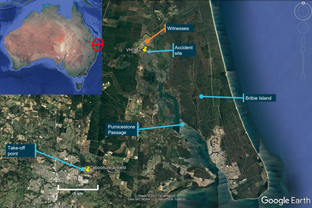
On 18 August 2021, at 0852 local time, an experimental amateur-built Stolp Acroduster II SA-750 aircraft, registered VH-YEL, departed the Caboolture airfield, Queensland, for a local aerobatic flight. The pilot was the sole occupant.
Shortly after, the crew of a helicopter operating in the vicinity, witnessed red and white debris falling from the sky. After searching the immediate area, the helicopter crew identified the main wreckage of VH-YEL.
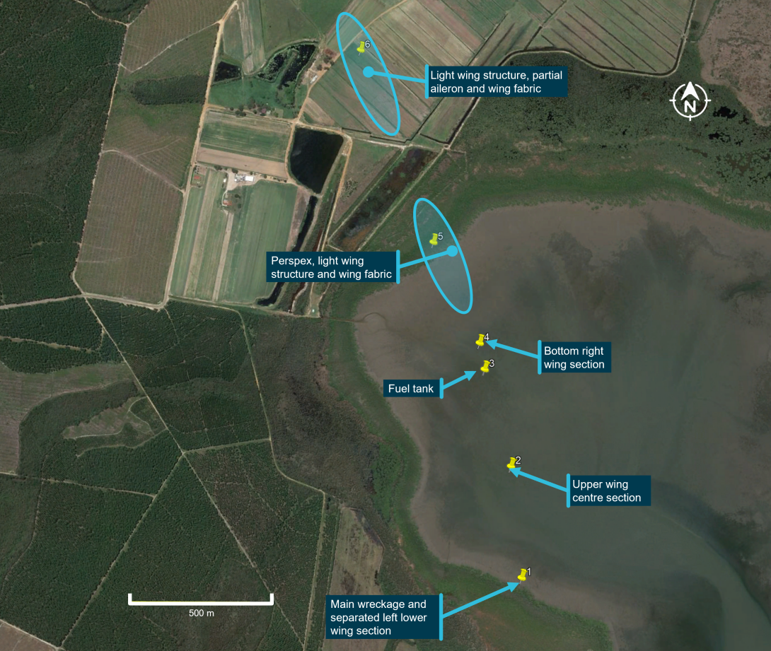
The majority of the wreckage came to rest inverted in tidal wetlands, close to the mainland shoreline of Pumicestone Passage, adjacent to Bribie Island (Figure 1). The aircraft was destroyed, and the pilot was fatally injured.
Initial assessment of the aircraft wreckage distribution by the ATSB at the accident site, indicated that the aircraft had sustained an in-flight break-up. The main aircraft wreckage and other components were recovered from the accident site and taken to a secure facility for detailed examination by the ATSB.
Figure 1: Aircraft departure point and accident location
Source: Google Earth, annotated by the ATSB
Context
Pilot information
The pilot held a valid Private Pilot Licence (Aeroplane) with 674.2 hours total flight time, including 108 flight hours conducted in VH-YEL. They also held a Private Pilot Licence (Helicopters) with an additional 102.9 hours flight experience. The pilot held the following ratings and endorsements:
- single-engine aeroplane class rating
- aerobatics and spinning flight activity endorsement
- manual pitch propeller control and tail wheel undercarriage design feature endorsements.
A review of the pilot’s logbook indicated that they had predominately focussed nearly all their flying since June 2016 on the conduct of aerobatics in a variety of different higher-performing single‑engine aircraft, including the accident aircraft.
The pilot held a valid Class 2 Aviation Medical Certificate with no restrictions.
Aircraft information
Experimental amateur-built aircraft
An amateur-built aircraft is an aircraft, the major portion (more than 50%) of which has been fabricated and assembled by a person who undertook the construction project solely for their own education or recreation (Advisory Circular AC-21.4(2) Amateur-built Experimental Aircraft – Certification). An amateur-built aircraft can be built from scratch based on an original design or established plans, or from a kit. Pilots and passengers of these aircraft operate under the premise of informed participation and accept the risk that these aircraft may not meet the same airworthiness safety standards as certified aircraft.
General information
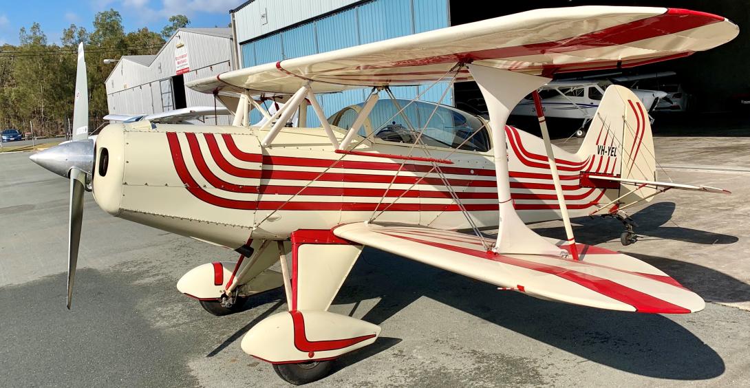
The Stolp Acroduster II SA-750 is a 2-seat amateur-built aerobatic bi-plane rated to +/- 9 g.[1] The aircraft was first introduced in 1971 as a plans-built aircraft, available from the Starduster Corporation in the United States. The current design owner (Aircraft Spruce) advised the ATSB that the plans for all Starduster Corporation aircraft had not been modified since first produced. The aircraft fuselage is constructed of welded steel tube and the wings incorporate wooden structure with steel tube internal supports. The majority of the aircraft is covered in fabric. It is powered by a 4-cylinder piston engine driving a 2-blade fixed pitch propeller (Figure 2).
Figure 2: VH-YEL Stolp Acroduster II SA-750
Source: Supplied
There are several other plans-built Starduster Corporation aircraft variants developed by the same designer that share similar design features, such as the Starduster and single seat Acroduster (SA-700). However, only the Acroduster series aircraft share the same upper wing attachment points. There were about 130 Acroduster SA-700/750 aircraft that were completed with 2 of them being on the Australian register. Some components for the aircraft were able to be purchased as kits or raw materials.
VH-YEL details
The aircraft’s plans were supplied from the Stolp Starduster Corporation in 1976 and the aircraft was constructed in the United States with a serial number of T-02. The aircraft was first registered as N97177 and first flew in 1981. It was disassembled and shipped to Australia in 2003. At that time, the aircraft had accumulated about 430 flight hours.
The aircraft was re-registered in Australia in 2007 as VH-YEL and was operated under the experimental category.[2] The aircraft was purchased by the accident pilot on 9 July 2019. It was maintained in accordance with the Civil Aviation Safety Authority maintenance schedule 5[3] and, at the time of the accident, had accumulated about 717 flight hours. The last periodic maintenance inspection was conducted on 27 August 2020 at 687.3 hours total time‑in‑service, with the next inspection due 9 days after the accident.
Wing attachment and bracing description
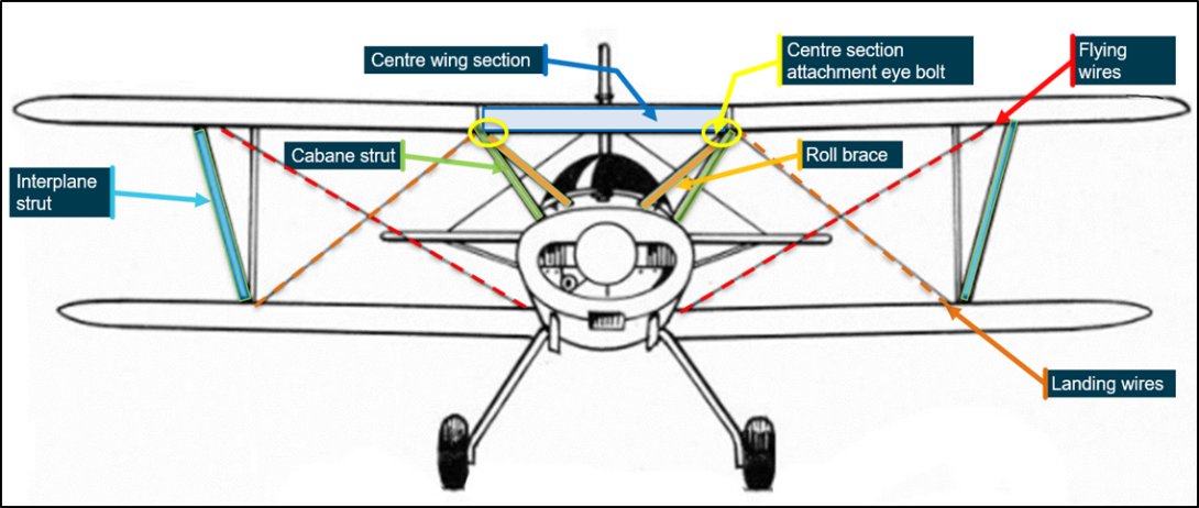
The lower wings of the Acroduster SA-700/750 were directly attached to the lower fuselage at 2 wing root attachment points on each side. The upper wings incorporated the left, right and centre sections (Figure 3). The centre section was attached to the fuselage by eye bolts (yellow) that then connected to the forward cabane struts (green) and roll braces (light orange). The wings were externally braced against each other using flying wires (red), landing wires (dark orange), and interplane struts (blue). In-flight, the lower wing outboard sections were supported by the upper wing outboard sections through the interplane struts and flying wires.
Figure 3: Wing bracing and attachment
Source: Starduster, annotated by the ATSB
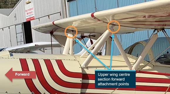
The cabane struts and roll braces were provided to support and attach the centre section of the upper wing to the fuselage. Eye bolts had been manufactured to thread into the upper portion of each cabane strut and completed the attachment between the upper wing centre section and the struts (Figure 4). The eye bolts were adjustable in length through their threaded section.
Figure 4: Upper wing centre section attachment
Source: Supplied, annotated by the ATSB
Technical support and eye bolt inspection requirements
There was no in-service technical support for the aircraft type provided by the design owner (Aircraft Spruce), nor was there required to be by regulations for aircraft in the experimental category. Such support would typically include:
- the communication and analysis of service difficulties, defects, design issues and or technical failures of components
- detailing specific type maintenance inspection requirements based on known design issues
- providing technical assistance for product improvements to identify emerging design issues and to implement design change.
The only method to identify and mitigate design issues with the aircraft was via word of mouth, magazine articles, amateur builder associations, or on-line aircraft forums where owners could discuss safety issues and design problems among themselves.
Apart from the requirement to complete a general inspection of the wing attachment points and wing structure periodically for condition and security, the aircraft type did not have a specific detailed inspection schedule for the eye bolts or roll braces to ensure their ongoing airworthiness.
In addition, the aircraft type did not have a specified life‑limit to replace the eye bolts at set flight hours and/or cycles, rather, they were an on‑condition replacement.
Meteorological information
Closed circuit television footage at Caboolture airfield showed there was little to no wind, good visibility, and broken[4] cloud with no rain at the time the aircraft departed. This was consistent with the Bureau of Meteorology graphical area forecast, which further indicated wind speeds of 17‑20 kt from the south, south‑south-east between 1,000-5,000 ft. Therefore, weather was not considered to be a contributing factor to the accident.
Aircraft radar surveillance information
Recorded surveillance data was obtained from Airservices Australia. As the aircraft was not fitted with a transponder, only primary radar returns[5] were available. The coverage will detect aircraft at, or above heights depending on the aircraft’s proximity to radar coverage and terrain shielding. Due to the limitations of primary radar and terrain shielding, there were gaps in the radar recording and the aircraft’s altitude, speed and timing data was not available.
However, there was limited radar data in respect to an aircraft departing Caboolture and a flight path consistent with VH-YEL. This included termination of the flight in the immediate vicinity of the accident site. The ATSB’s analysis of the recorded flight path data showed that the aircraft was conducting several minutes of aerobatic manoeuvring leading up to and likely during the in-flight break‑up sequence.
Wreckage and impact information
The aircraft wreckage was located on tidal mud flats and farmland, it was spread over a distance of about 2.4 km. The trail was oriented in a south-east to north-west direction consistent with wind direction on the day.
The main wreckage consisted of the fuselage, tail, and outer-wing sections still attached to the fuselage by the flying and landing wires. The left lower inboard wing section had separated from the aircraft but was located adjacent to the main wreckage. The upper wing centre section was located about 500 m away from the main wreckage. The majority of the remaining scattered debris consisted of light wooden sections of wing structure, wing skin fabric, panels and windshield fragments (Figure 5).
Figure 5: Wreckage trail distribution over mud flats and farmland
Source: Google Earth, annotated by the ATSB
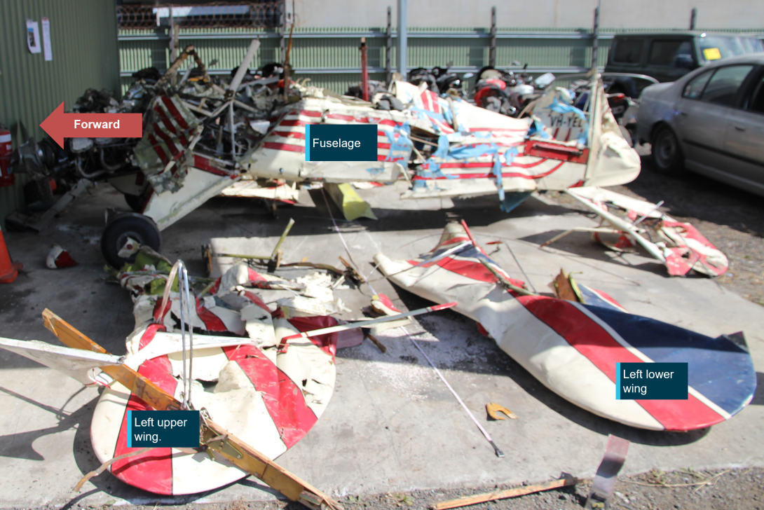
The main wreckage was recovered by barge at the changing of the tide and was transported to a secure storage facility for examination by the ATSB (Figure 6). Reconstruction of the sections of recovered aircraft identified that:
- the majority of the parts were accounted for with the exception of the right interplane strut
- the aircraft flight controls had no pre-impact defects
- the fuselage, wings, flying and landing wires had no pre-impact defects
- the forward cabane strut upper wing attachment point eye bolts to the centre-wing structure had fractured and displayed evidence of pre-existing fatigue cracking
- there was no evidence of propeller rotation at impact, however, the engine most likely stopped from fuel starvation during the in-flight break-up sequence.
Figure 6: VH-YEL as recovered and partially reassembled
Source: ATSB
Upper centre wing attachment points
Technical examination of the upper centre wing attachment – summary
Both forward cabane struts and roll braces, and the attaching hardware were cleaned and treated against corrosion during the wreckage recovery process. They were removed from the aircraft and sent to the ATSB’s technical facilities in Canberra for detailed examination. For further detail refer to the materials analysis report at Appendix A. The examination identified:
- The left and right eye bolts were cadmium plated, had rolled threads, and were likely made of 4140 alloy steel.
- The eye bolts had no observable manufacturing defects.
- There were fatigue cracks in a fore/aft direction through 35% of the left eye bolt threaded cross section with the remaining material fractured in overload.
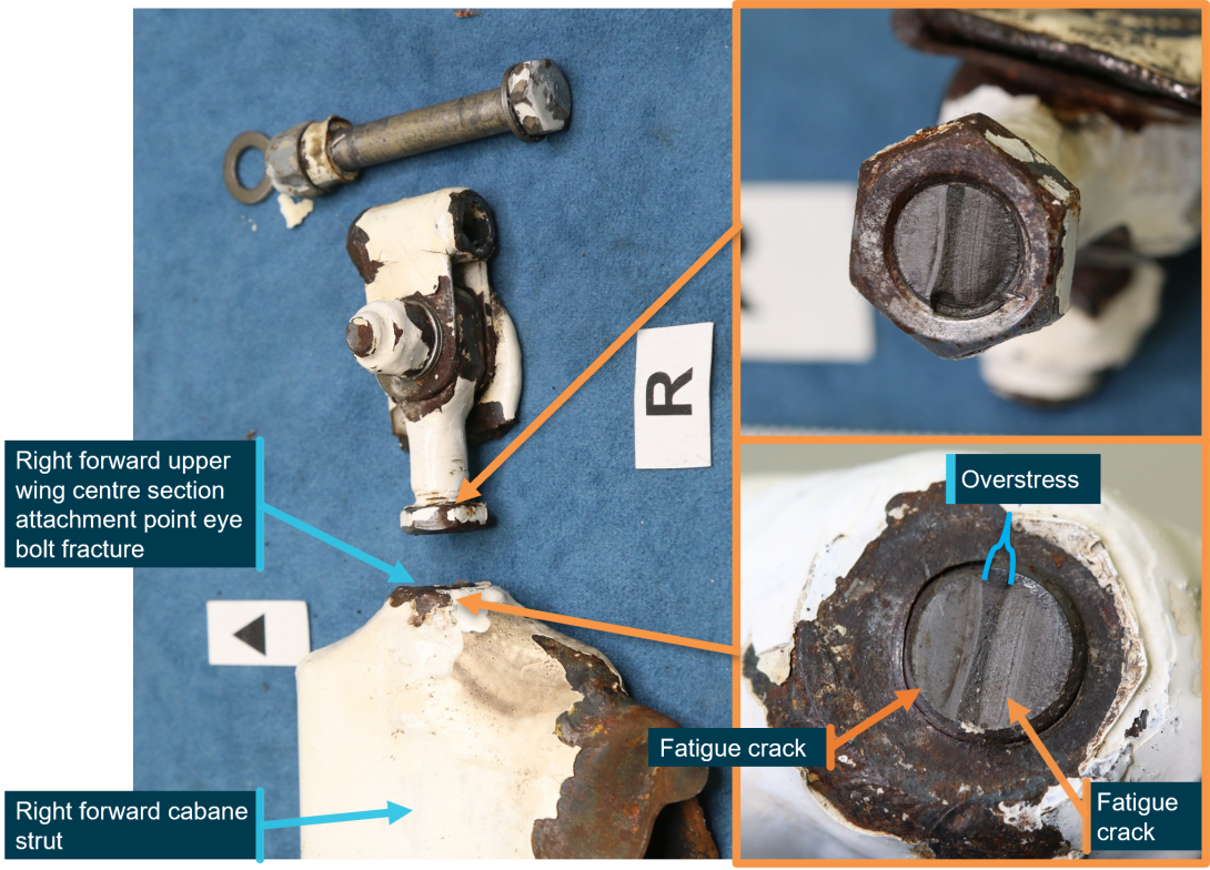
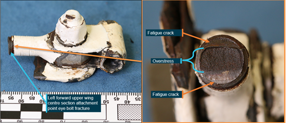
- There were uniaxial fatigue cracks in a fore/aft direction through 85% of the right eye bolt threaded cross section with the remaining material fractured in overload (Figure 7).
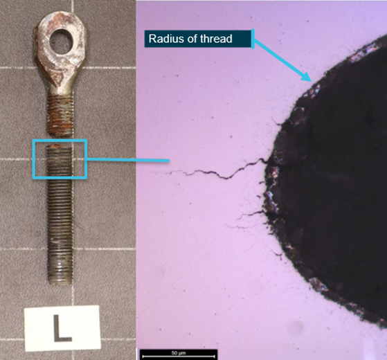
- There were several areas of additional micro-cracking present in the threaded portion of the forward eye bolts.
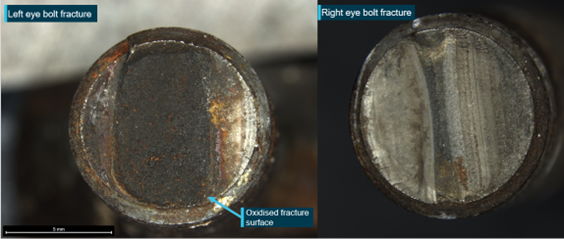
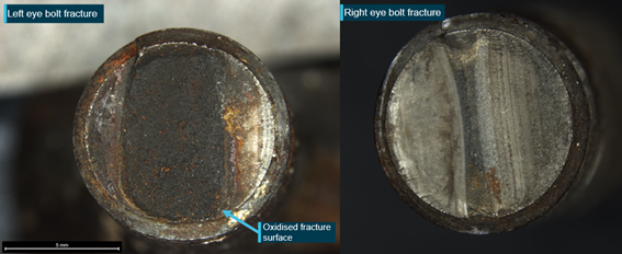
- The left eye bolt fracture surfaces had significant corrosion when compared to the right eye bolt fracture surfaces. This indicated that the left eye bolt had completely fractured some time before the accident flight (Figure 8).
- Visual examination of both roll braces indicated that they had fractured at their upper connection.
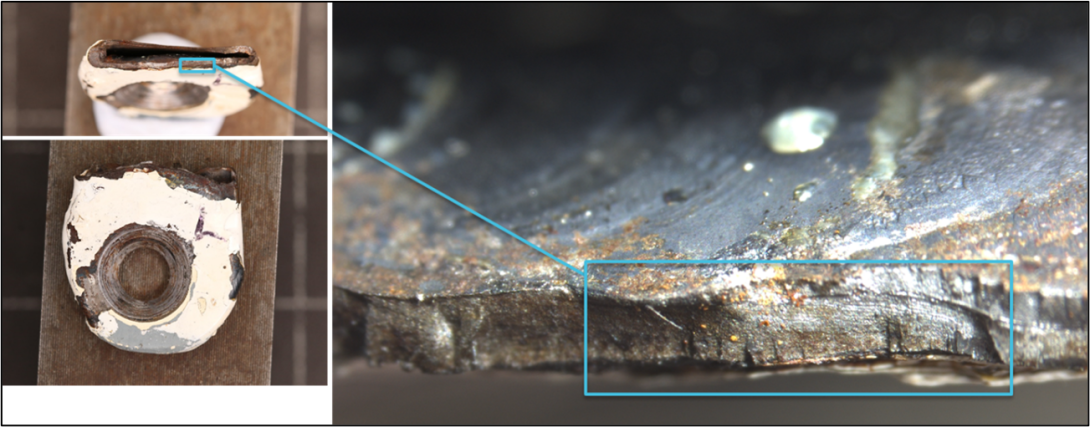
- The left roll brace fracture surface that was coincident with the position of the upper cabane strut eye bolts had fatigue cracks through 60% of its cross-section.
- Due to the development of corrosion damage to the fracture surfaces, it could not be ascertained if the right roll brace had also developed fatigue cracking.
Figure 7: Right eye bolt, cabane strut and fracture surface
Source: ATSB
Figure 8: Corrosion level differences between left and right eye bolt fracture surfaces
Source: ATSB
The location of the crack on the right forward cabane strut eye bolt was directly under the securing nut, making it imposssible to identify the fatigue crack without dissassembling the attachment point and removal of the eye bolt. The location of the crack on the left forward cabane strut was directly above the securing nut and would have been difficult to identify while it was forming in the threaded section without dissassembly and removal of the eye bolt from the cabane strut.
Eye bolt history
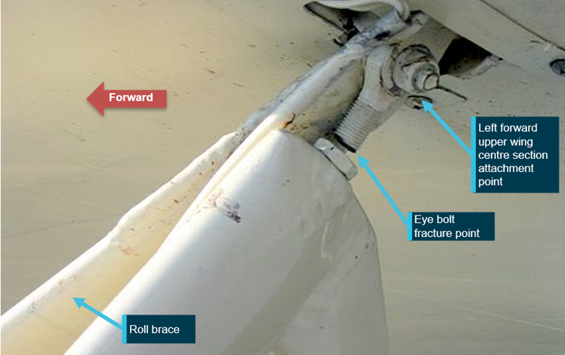
A subject matter expert familiar with the early design and development of the aircraft type indicated that there has been a history of cabane strut eye bolt cracking in the same area of the threaded section as occurred with VH-YEL. They provided the ATSB with an image taken 2 decades before this incident of an Acroduster SA-750 where a left forward upper wing cabane strut eye bolt fractured completely through its threaded section. That fracture was in the same location as VH-YEL. The left roll brace was the only remaining structure providing support to that section of the wing (Figure 9). It could not be determined how long prior, or for how many hours the aircraft had flown with the failed eye bolt.
Figure 9: Previous Acroduster SA-750 with fractured wing attachment eye bolt
Source: Supplied, annotated by the ATSB
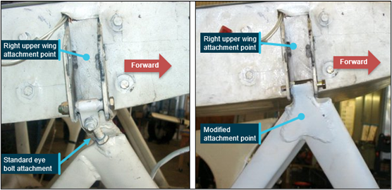
The ATSB was further advised that some owners of Acroduster aircraft made modifications to the upper wing attachment points. The modification removed the eye bolts and replaced them with a welded structure, which attached directly to the upper wing attachment point, effectively strengthening the attachment points (Figure 10). The ATSB notes that the modification shown was not approved by the aircraft design owner and had been added by experimental amateur-built owners. Advice on such modifications should be sought from a suitably qualified aeronautical engineer on any design changes undertaken.
Figure 10: Right-side upper wing centre section attachment point with a standard eye bolt attachment (left) and a modified attachment (right)
Source: Supplied, annotated by the ATSB
Roll brace history
The Starduster Magazine had been produced as a technical document to assist amateur builders of Starduster company aircraft including the Acroduster aircraft. In the April 1980 edition, the author reported that while completing an aircraft inspection, cracks were identified in the roll brace and the cabane strut. Notably:
The most significant repair was on the Cabane struts, sheet 5, items 4 and 5. One of them was cracked, and the brace strut [roll brace] on that side was carrying no load.
As such, the author provided a cautionary note:
If you are already flying your machine, we recommend that you keep a careful eye on these sway [roll] braces, and carefully inspect them both visually and by shaking, before your first flight of the day. You should change them at the next annual inspection.
The article stated that a modification had been made to replace the steel tube roll braces with stainless steel material that was the same type as the flying wires. The last edition of Starduster Magazine was produced in October 1985.
Safety analysis
Introduction
While conducting an aerobatic flight, the aircraft sustained an in-flight break-up and a subsequent collision with the terrain. The pilot was fatally injured and the aircraft was destroyed. Adverse weather was not identified as a factor in the accident flight.
The following analysis examines what contributed to the in-flight break-up sequence and technical support, design, and maintenance inspection considerations.
In-flight break-up sequence
The aircraft wreckage was distributed over 2.4 km, with the centre wing section found about 500 m away from the main wreckage. The ATSB’s metallurgical examination of the forward left and right upper wing centre section attachment eye bolts (eye bolts) from VH-YEL did not identify any manufacturing defects or anomalies outside of the limited design specifications provided. However, the ATSB’s inspection found areas of significant pre-existing fatigue cracking in the threaded portions of the eye bolts. There was also significant corrosion on the fracture surfaces of the left eye bolt, when compared to the right eye bolt. This indicated the left eye bolt had failed some time before the accident flight.
Further, inspection of the left roll brace also identified areas of fatigue cracking. It was likely that, when the left eye bolt failed, the flight loads transferred to the adjacent structure, which was the left roll brace. This increased the fatigue inducing flight loads acting on the roll brace. A previous failure of an eye bolt that occurred on another Acroduster aircraft showed that aircraft flight loads could be supported by the respective roll brace.
Subsequently, it was likely that the right eye bolt and left roll brace fatigue cracks propagated to a critical size and that the remaining material was no longer able to sustain normal flight loads and consequently failed in overstress. They, along with the previously failed left eye bolt initiated the in‑flight break-up sequence.
Detection of the cracks
In this accident, the fatigue cracks on the cabane struts formed in an area of the eye bolts that were obscured by the securing nuts and threads of the eye bolts. Therefore, the cracks would not have likely been readily identifiable during standard maintenance inspections without disassembling the attachment points. However, as the last periodic inspection occurred about 1 year prior to the accident, it could not be determined if the cracks would have been present at that time.
Aircraft design and maintenance
As discussed above, the ATSB’s examination found fatigue cracking in both eye bolts and the left roll brace. An expert familiar with the Acroduster design had stated that there was a history of eye bolt cracking as previously evidenced on another aircraft. Similarly, the Starduster Magazine, which had ceased publishing in 1985, had mentioned incidents of roll brace cracking.
Consequently, some Acroduster owners had modified the attachment points to remove the eye bolts and replaced the roll braces with bracing wires. Those design improvements were made at a local level by individual aircraft owners, rather than through direct and broad reaching technical support provided by the design owner. Without design owner tracking and analysis of historic in‑service component and structural design issues:
- broad reaching structural design improvements will not be made
- additional maintenance inspections to identify defects in areas with known issues will not be implemented
- time/cycle component retirement life assessments will not be conducted.
In this case, the aircraft was provided to the builder in a basic kit form, with a set of design plans that had not changed since they were originally produced about 50 years ago. Further, there was no explicit requirement to inspect the eye bolts or roll braces in detail, despite being a known area for fatigue cracking and on-condition component with no specified replacement interval.
Therefore, without a mechanism for identifying product improvements, Acroduster owners may not be aware of possible design issues and enhancements made by others.
Findings
|
ATSB investigation report findings focus on safety factors (that is, events and conditions that increase risk). Safety factors include ‘contributing factors’ and ‘other factors that increased risk’ (that is, factors that did not meet the definition of a contributing factor for this occurrence but were still considered important to include in the report for the purpose of increasing awareness and enhancing safety). In addition, ‘other findings’ may be included to provide important information about topics other than safety factors. These findings should not be read as apportioning blame or liability to any particular organisation or individual. |
From the evidence available, the following findings are made with respect to the in-flight break-up accident involving a Stolp Acroduster II SA750, registered VH-YEL, on 18 August 2021.
Contributing factors
Other factors that increased risk
- The eye bolt fatigue cracks formed in areas that would not be easily identifiable during the periodic maintenance inspections without the requirement for removal of the eye bolts from the cabane struts. This reduced the opportunity to identify fatigue cracks before they propagated to a critical size.
- There was no provision for product improvements to identify emerging design issues and to implement design change or additional maintenance inspections, nor was this required for aircraft in the experimental category.
Safety actions
| Whether or not the ATSB identifies safety issues in the course of an investigation, relevant organisations may proactively initiate safety action in order to reduce their safety risk. All of the directly involved parties are invited to provide submissions to this draft report. As part of that process, each organisation is asked to communicate what safety actions, if any, they have carried out to reduce the risk associated with this type of occurrences in the future. The ATSB has so far been advised of the following proactive safety action in response to this occurrence. |
Safety action by the ATSB
Shortly after the accident, the ATSB notified the Civil Aviation Safety Authority, the United States National Transportation Safety Board and Federal Aviation Administration, the kit plane design/material provider and the Experimental Aircraft Association that fatigue cracking had been identified within the upper wing centre section attachment eye bolts. The ATSB also contacted the owner of the only other Stolp Acroduster II SA-750 on the Australian civil aircraft register and informed them of the fatigue cracking.
Further, the ATSB released a safety advisory notice (AO-2021-032-SAN-001) with the preliminary report to inform aircraft type owners of the circumstances of the accident and the fatigue crack issue. The notice stated that:
The Australian Transport Safety Bureau advises all owners, operators and maintainers of Stolp Acroduster SA‑700/750 aircraft to consider the safety implications of the initial findings of this investigation regarding the fatigue cracking on forward cabane strut upper-wing centre-section attachment eye bolts, and take action where considered appropriate to ensure that their aircraft remain airworthy.
Safety action by the Experimental Aircraft Association
In November 2021, the United States Experimental Aircraft Association released a notice on its website informing its members of the Acroduster accident and linking the notice to the ATSB preliminary report and safety advisory notice.
Safety action by design owner (Aircraft Spruce)
In November 2021, the design owner issued a safety advisory notice to every purchaser of Starduster and Acroduster design plans since 2003. The notice informed customers about the fatigue cracking and provided a link to the ATSB preliminary report.
Safety action by the United States Federal Aviation Administration
In November 2021, the United States Federal Aviation Administration issued a notice to more than 280,000 web subscribers informing them of the wing attachment point fatigue cracks and providing a link to the ATSB preliminary report and safety advisory notice.
Sources and submissions
Sources of information
The sources of information during the investigation included the:
- aircraft design owner (Aircraft Spruce)
- aircraft design subject matter expert
- Experimental Aircraft Association
- United States National Transportation Safety Board
- United States Federal Aviation Administration
- various experimental aircraft forums
- Airservices Australia
- Civil Aviation Safety Authority.
Submissions
Under section 26 of the Transport Safety Investigation Act 2003, the ATSB may provide a draft report, on a confidential basis, to any person whom the ATSB considers appropriate. That section allows a person receiving a draft report to make submissions to the ATSB about the draft report.
A draft of this report was provided to the following directly involved parties:
- aircraft design owner (Aircraft Spruce)
- aircraft design subject matter expert
- Experimental Aircraft Association
- United States National Transportation Safety Board
- United States Federal Aviation Administration
- Airservices Australia
- Civil Aviation Safety Authority.
There were no submissions received.
Appendix A: Materials examination of the wing structure
Scope
The work scope was limited to examining the cabane struts and associated components for evidence of defects or pre-existing conditions that may have contributed to the structural break-up of the upper wing. The following fragments from the aircraft were examined in further detail:
- forward attachment eye bolts from the cabane struts to the upper centre wing
- left and right cabane strut
- left and right roll brace.
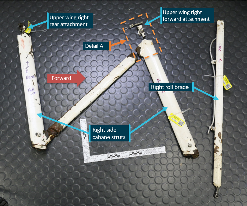
Figure A1 shows the right cabane struts and roll brace. The area notated as Detail A (also see Figure A2) shows the fractured upper wing attachment point.
Figure A1: Right cabane struts, roll brace and upper wing attachment points
Source: ATSB
Technical examination of retained components
Eye bolt examination
The ATSB’s laboratory examination confirmed that fatigue cracks had developed in the forward eye bolts for both the left and right cabane struts. The examination determined that the cracking had initiated in the thread root region along the threaded shank of each bolt. Distinctly opposing features on the fracture surfaces indicated that the stresses leading to crack growth were likely from fore/aft uniaxial bending of each bolt during service.
The fatigue cracking had extended through approximately 85% of the right eye bolt and about 35% of the left eye bolt cross-section prior to ductile overstress fracture. (Figure A2 and A3).
Figure A2: Right cabane strut forward upper wing attachment eye bolt showing evidence of significant fatigue cracking through the threaded portion (Detail A from Figure A1)
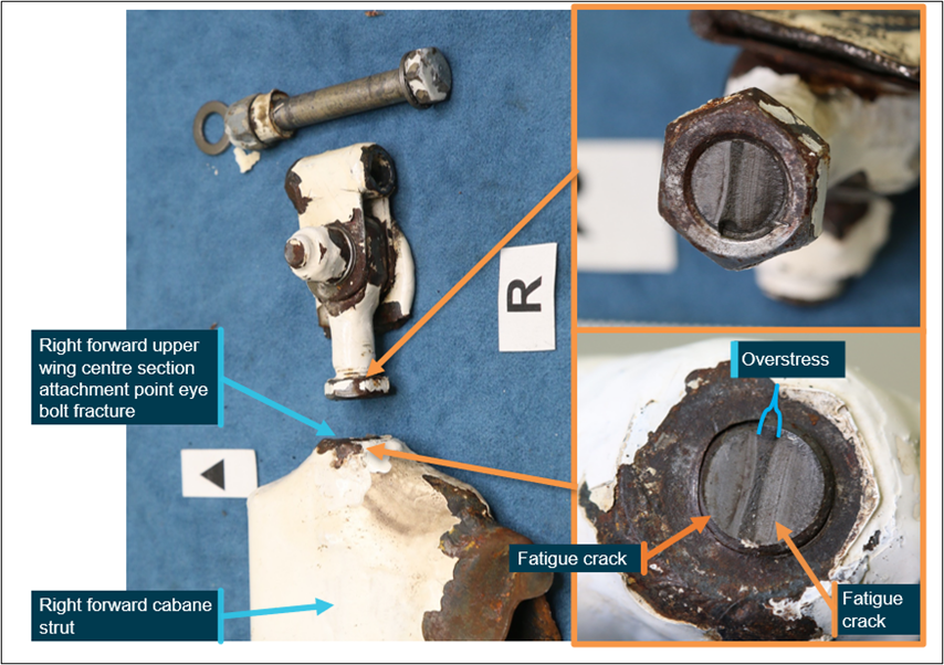
Figure A3: Left cabane strut forward upper wing attachment eye bolt showing evidence of fatigue cracking through the threaded portion
Source: ATSB
The use of a scanning electron microscope during the fracture surface examination confirmed that fatigue cracking for both eye bolts had initiated in the thread root region at multiple locations. There was no specific damage to the threads in either the left or right eye bolt that might have otherwise provided an initiating defect. Ratchet marks were identified within the thread root. Each ratchet mark was initially a micro-crack that then linked to form a broader crack front. The presence of many ratchet marks on each of the fracture surfaces was an indicator that the bolts were probably quite highly stressed from operation of the aircraft.
The scanning electron microscope examination also identified the presence of additional micro-cracking in the thread root region of each bolt that extended further along the shank. The extent of cracking was later confirmed by metallurgical sectioning of the left eye bolt whereby numerous smaller penetrating cracks had developed along the bolt shank threads (Figure A4).
Figure A4: The fractured left eye bolt and a corresponding metallurgical cross-section that shows additional microcracking had developed within the threads of the bolt shank
Source: ATSB
An optical comparison between the fracture surfaces of the left and right eye bolts identified notable differences between each bolt. The left eye bolt had significantly more corrosion and associated oxidation of the majority of the fracture surface, when compared with right eye bolt (Figure A5). That physical difference provided evidence to identify that the left eye bolt had likely been the first to fracture, followed sometime later by fracture of the right eye bolt.
Figure A5: Eye bolt fracture surfaces showing the difference in the level of corrosion between the left and right eye bolt
Source: ATSB
Eye bolt specifications
There were no engineering drawings or associated material specifications available to support the metallurgical examination of the eye bolts. However, they were consistent in appearance to the 3/8-in ‘special bolts’ reported by the aircraft design owner to have been intended for use in the Acroduster cabane struts. It was further indicated to the ATSB that the eye bolts were manufactured at a United States metal fabrication shop from a 4140 low-alloy steel, heat treated, and then cadmium plated.
ATSB’s metallurgical analysis of the eye bolts from VH-YEL determined that:
- they were chemically consistent with a low-alloy steel that was likely to be 4140 (or a close equivalent alloy)
- contained a microstructure of tempered martensite that was consistent with the application of a quench hardening and tempering heat-treating process at the time of manufacture
- on measurement the bolts had an average Vickers hardness of 356.4 HV0.1, which after conversion showed a tensile strength of 166 ksi (1,144 MPa), and that value was in the correct strength range for a 4140 steel in the quenched and tempered condition
- each bolt had been cadmium plated
- the bolt threads had probably been rolled (not machine or die cut)
- no metallurgical defects or other damage was evident surrounding the fatigue crack origins.
Based on this evidence, it was likely that the fractured eye bolts from VH-YEL were those originally manufactured for use for the aircraft type. In addition, there were no metallurgical defects identified that might have otherwise predisposed the bolts to premature fatigue cracking.
Roll brace examination
Visual examination of both roll braces that had been attached to their respective cabane strut showed that they had fractured at the upper connection to the trunnion joint. Each fracture location was coincident with the position of the upper cabane strut eye bolts. ATSB’s laboratory examination identified that the left roll brace had fractured with about 60% of its cross-section showing features consistent with fatigue (such as crack progression markers and a flat surface profile) (Figure A6). The remainder of the fracture was one of ductile overstress.
The right roll brace contained an almost identical fracture profile, however, due to the extent of corrosion development, no salient features could be identified to conclude whether the strut contained fatigue cracks prior to its final fracture.
Figure A6: Optical examination of the roll brace from the left cabane strut showed indications of pre-existing fatigue in the welded region
Source: ATSB
Purpose of safety investigationsThe objective of a safety investigation is to enhance transport safety. This is done through:
It is not a function of the ATSB to apportion blame or provide a means for determining liability. At the same time, an investigation report must include factual material of sufficient weight to support the analysis and findings. At all times the ATSB endeavours to balance the use of material that could imply adverse comment with the need to properly explain what happened, and why, in a fair and unbiased manner. The ATSB does not investigate for the purpose of taking administrative, regulatory or criminal action. TerminologyAn explanation of terminology used in ATSB investigation reports is available here. This includes terms such as occurrence, contributing factor, other factor that increased risk, and safety issue. Publishing informationReleased in accordance with section 25 of the Transport Safety Investigation Act 2003 Published by: Australian Transport Safety Bureau © Commonwealth of Australia 2023
Ownership of intellectual property rights in this publication Unless otherwise noted, copyright (and any other intellectual property rights, if any) in this report publication is owned by the Commonwealth of Australia. Creative Commons licence With the exception of the Coat of Arms, ATSB logo, and photos and graphics in which a third party holds copyright, this publication is licensed under a Creative Commons Attribution 3.0 Australia licence. Creative Commons Attribution 3.0 Australia Licence is a standard form licence agreement that allows you to copy, distribute, transmit and adapt this publication provided that you attribute the work. The ATSB’s preference is that you attribute this publication (and any material sourced from it) using the following wording: Source: Australian Transport Safety Bureau Copyright in material obtained from other agencies, private individuals or organisations, belongs to those agencies, individuals or organisations. Where you wish to use their material, you will need to contact them directly. |
[1] G load: the nominal value for acceleration. In-flight, g load represents the combined effects of flight manoeuvring loads and turbulence, and can have a positive or negative value.
[2] Experimental category aircraft include all amateur-built aircraft that are not certified designs.
[3] A generic maintenance schedule designed by the Civil Aviation Safety Authority for aircraft that either had no manufacturer’s maintenance schedule or had an inadequate maintenance schedule.
[4] Cloud cover: in aviation, cloud cover is reported using words that denote the extent of the cover – ‘broken’ indicates that more than half to almost all the sky is covered.
[5] Primary radar is a system where a ground-based antenna transmits a radar pulse, then listens for the small amount of return energy that is reflected from an aircraft. The time delay between the transmission of the pulse and the receipt of the reflected return is a measure of the range. This is effective within a short range from the radar head. Regardless of whether an aircraft has a transponder, primary radar will detect an aircraft’s position, height and approximate airspeed.


