What happened
On 17 March 2017, a Saab 340B aircraft, registered VH-NRX, was operated by Regional Express (Rex) as flight RXA768 on a routine passenger flight from Albury, New South Wales (NSW) to Sydney, NSW. On board the aircraft were 16 passengers and three crew.
About 102 km (55 NM) south-west of Sydney Airport, the crew noticed uncommanded engine indications and began the necessary checklists. While undertaking the checklist items, the crew experienced minor vibrations from the right engine. These vibrations worsened as the checklist progressed and became visually evident to the first officer. As a result, the crew commenced the engine shutdown procedure. During the procedure, the propeller separated from the aircraft. The crew made a PAN PAN[1] call to air traffic control, and completed the engine shutdown procedure. The aircraft landed without incident at Sydney Airport.
On 21 March 2017, the NSW Police Aviation Support Branch located the propeller in an area under dense forest about 19 km (10 NM) south-west of Sydney Airport.
What the ATSB found
An inspection of the aircraft by the ATSB at Sydney Airport identified that the propeller gearbox (PGB) propeller shaft had fractured, leading to the separation of the propeller. Subsequent laboratory analysis of the propeller shaft revealed that the failure occurred as a result of a fatigue crack that had initiated from the PGB propeller shaft flange dowel pin hole.
The ATSB found that the manufacturer’s maintenance documentation did not include specific inspection procedures to detect fatigue cracking of the propeller shaft. In addition, the operator’s inspection worksheets did not provide for the recording of inspection findings as defined within documented procedures. Consequently, this may not have provided for the best opportunity to ensure potential defects were identified, recorded and monitored.
What's been done as a result
Following the occurrence, the engine manufacturer (General Electric) released a number of service bulletins (SB 72-0530 and SB 72-0531) requiring immediate inspection of the PGB propeller shaft. Changes were also made to the engine maintenance manuals to include more ongoing detailed inspections of this area. Additionally, the United States Federal Aviation Administration, issued airworthiness directive AD 2018-03-13, on 14 February 2018, which required initial and repetitive visual inspection and fluorescent-penetrant inspection (FPI) of the main propeller shaft for affected engines.
Safety message
This occurrence highlighted how non-life-limited components such as a propeller shaft may still develop defects and fail in-flight. Appropriate training, the use of checklists and effective crew interaction, provide the best opportunity for a positive outcome in the event of such a failure affecting flight safety. Additionally, operators are reminded of the importance of having worksheets that accurately reflect the requirements and intentions of associated maintenance documentation.
__________
On 17 March 2017, a Saab 340B aircraft, registered VH-NRX was operated by Regional Express (Rex) as flight RXA768 on a routine passenger flight from Albury, New South Wales (NSW) to Sydney, NSW. On board the aircraft were 16 passengers and three crew.
About 109 km (55 NM) south-west of Sydney Airport, the crew noticed a slight fluctuation on the right engine torque gauge. The captain manipulated the power levers and condition lever to see if that could rectify the condition. When those actions were unable to stop the fluctuations, the crew proceeded to action the uncommanded engine operation procedures. While undertaking the checklist items, the crew experienced minor vibrations from the right engine. These vibrations worsened as the checklist progressed and became visually evident to the first officer. As a result, the crew commenced the engine shutdown procedure. During the engine shutdown procedure, at 1149 AEDT[2], the propeller separated from the aircraft. The crew made a PAN PAN[3] call to air traffic control, and completed the engine shutdown procedure. The aircraft landed without further incident at Sydney Airport.
Figure 1: The aircraft, VH-NRX, at Sydney Airport after the incident showing the point of separation of the propeller in close-up

Source: Grahame Hutchison and ATSB (modified)
An inspection of the aircraft by the ATSB at Sydney Airport identified that the propeller shaft had fractured, leading to the separation of the propeller.
On 21 March 2017, the NSW Police Aviation Support Branch (PolAir) located the propeller in an area under dense forest about 19 km (10 NM) south-west of Sydney Airport. The propeller was found with the flange section of propeller shaft secured to the propeller assembly and a fracture through the propeller shaft (Figure 2).
Figure 2: The separated propeller from VH-NRX
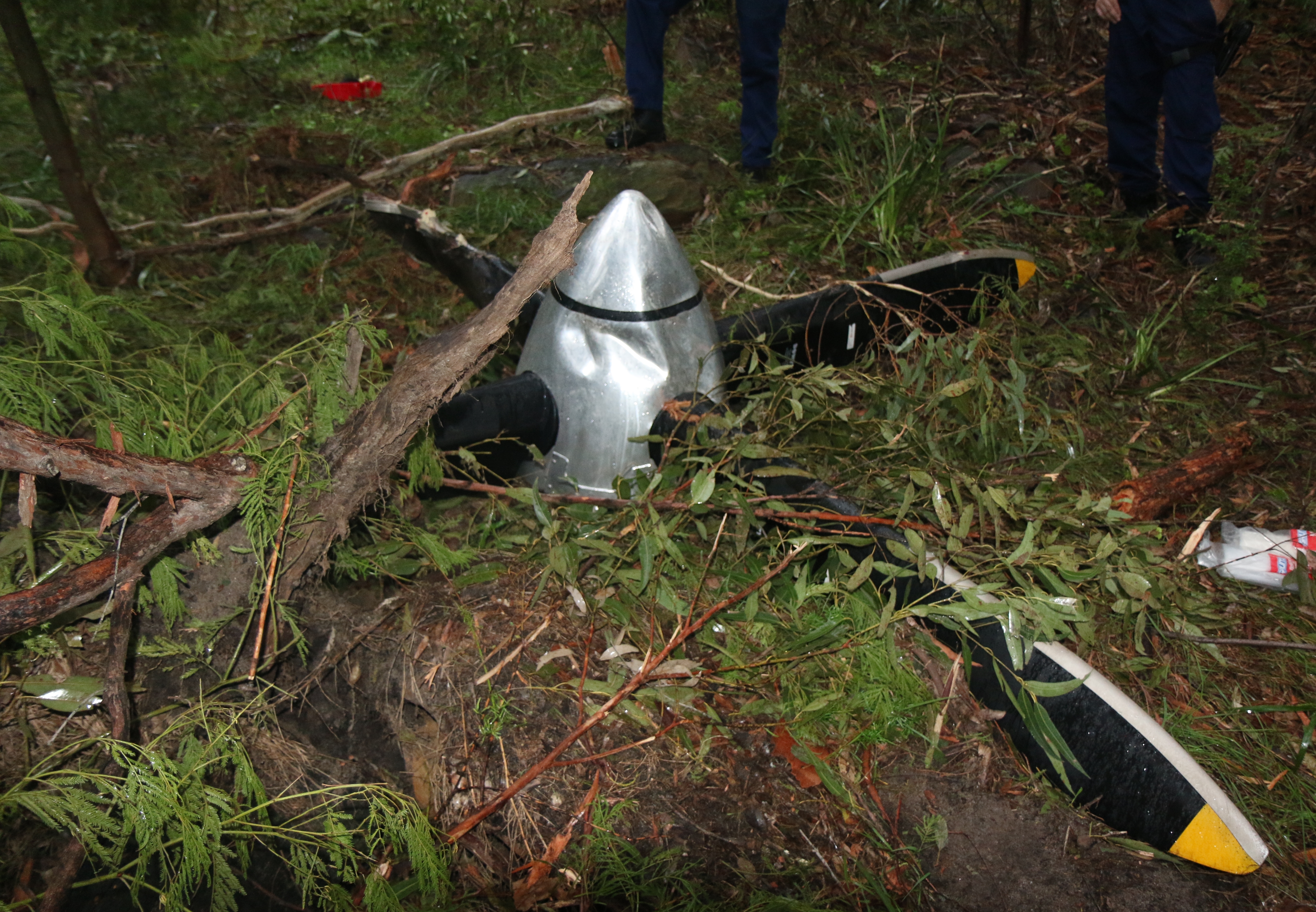 This image shows the propeller as found in bushland by PolAir about 19 km (10 NM) south-west of Sydney Airport.
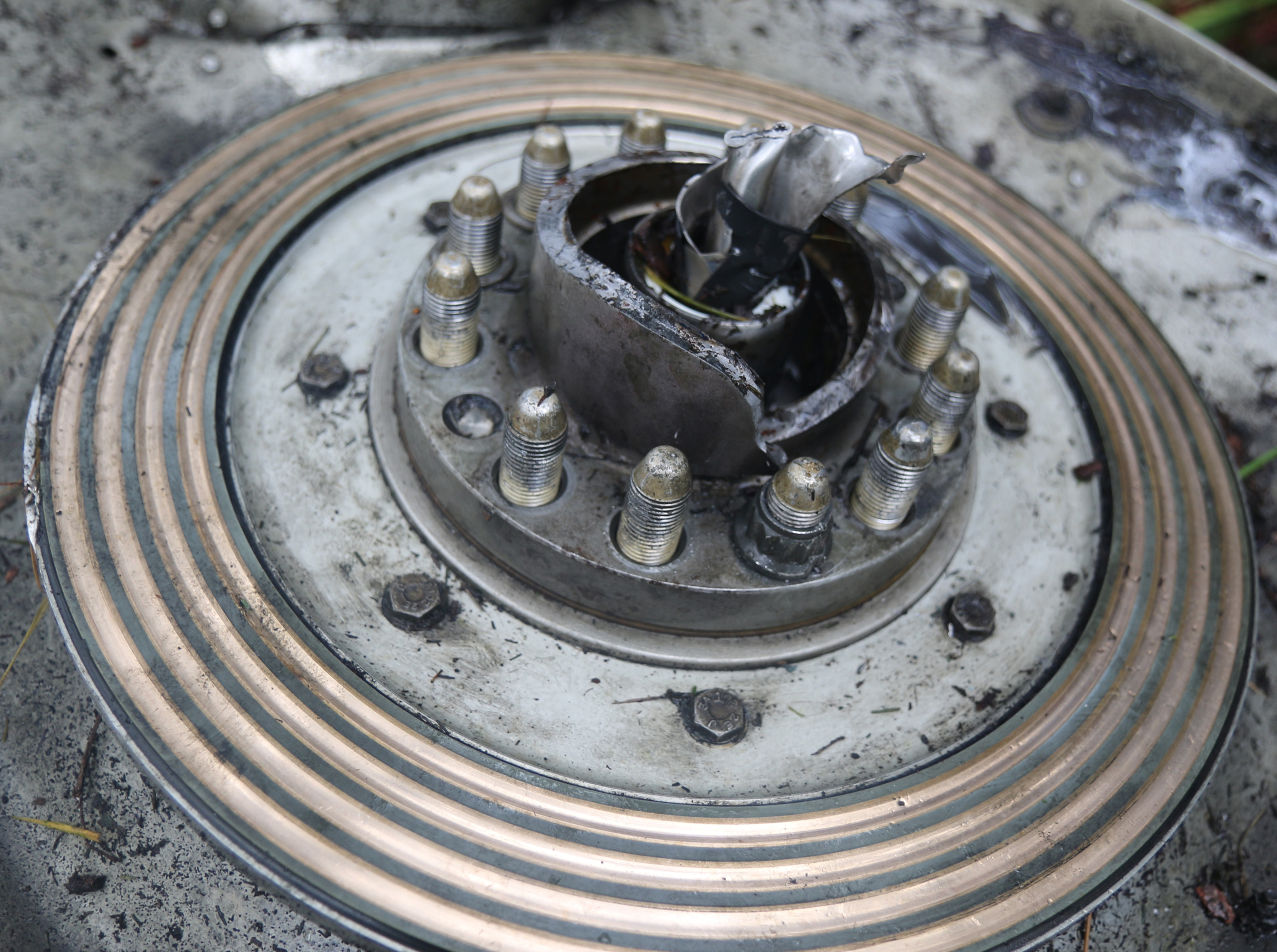
This shows the propeller flange still attached to the rear of the propeller. Note that the attachment nuts were in the process of being removed by ATSB investigators onsite, in order to release the flange.
Source: ATSB
__________
Recorded information
The ATSB downloaded and analysed data from the aircraft’s flight data and cockpit voice recorders (FDR and CVR, respectively). The data confirmed the crew had identified problems with the right engine torque gauge approximately 10 minutes before the failure of the propeller shaft and were in the process of actioning the relevant checklists when separation of the propeller from the aircraft occurred.
Personnel information
Both the captain and first officer held valid Class 1 medical certificates, and were appropriately qualified to conduct the flight. The captain had a total aeronautical experience of 6,631 hours, with 2,788 hours flying Saab 340 aircraft. The first officer had a total aeronautical experience of 1,683 hours with 1,410 hours flying Saab 340 aircraft.
Crew actions
Following the onset of the torque gauge fluctuations, the flight crew used the relevant the checklists, and worked together well as a crew. The crew did not divert from the checklists, and used additional services from air traffic control to manage the aircraft. The crew did not make any rapid decisions, and ensured that all options were considered before action was taken, including consideration of the go-around requirements due to weather.
Aircraft and engine information
The aircraft was a Saab 340B aircraft, serial number 340B-291, manufactured in 1991 and first registered in Australia in October 2004. At the time of the occurrence, the airframe had accumulated 39,625 hours and 43,112 flight cycles total time in service.
The aircraft was fitted with two General Electric (GE) CT7-9B turboprop engines. The CT7 engine consists of a modular power unit and a propeller gearbox (PGB). The engine can be fitted with a Dowty or Hamilton Sundstrand propeller.
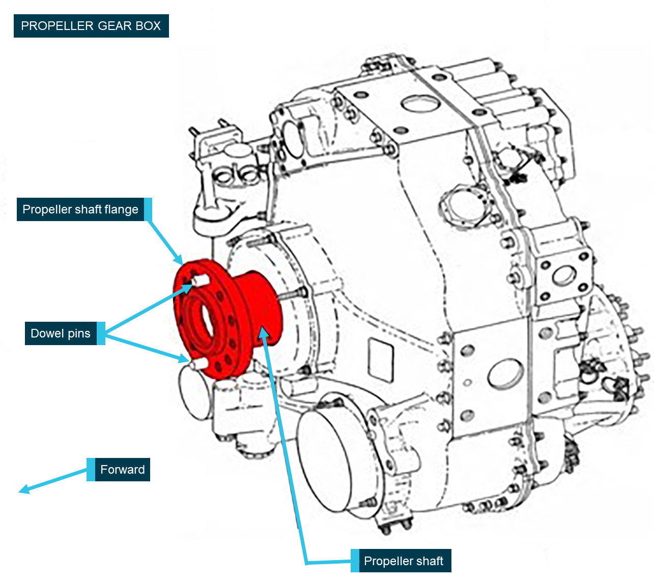
The propeller separated due to cracking between the propeller main shaft and the flanged region (Figure 3) on the right side PGB.
Figure 3: Propeller gearbox schematic highlighting the recovered section of the propeller shaft
Source: GE Aviation, modified by ATSB
The operator imported the event PGB module—serial number UDAG0153—from an international operator in December 2015. It entered service in Australia in March 2016 following fitment to the event engine—serial number (ESN) 785150—on 8 March 2016 on another company aircraft. The assembly—ESN 785150 and PGB UDAG0153—with Dowty propeller SN DRG/7635/91 was fitted to the right side of VH-NRX on 16 November 2016. At the time of the occurrence, the PGB had accumulated 46,406 hours (TSN) and 42,872 flight cycles since new (CSN).
Propeller shaft examination
Failure of the propeller occurred as a result of cracking between the propeller main shaft and the flanged region.
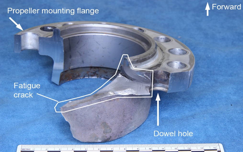
The propeller was found attached to the forward-facing (mating) flange by 12 self-locking nuts and two dowel pins, which are a press fit into the dowel pin holes. Following removal of the bolts, the fractured section of the propeller shaft was removed. The dowel pins were still installed in their respective dowel pin holes, and the non-metallic gasket/shim located between the propeller shaft flange and the propeller hub did not exhibit any wear or damage. The flange section of the propeller shaft was sent to the ATSB’s Canberra facilities for further examination (Figure 4).
Figure 4: Separated shaft section in their as-received condition
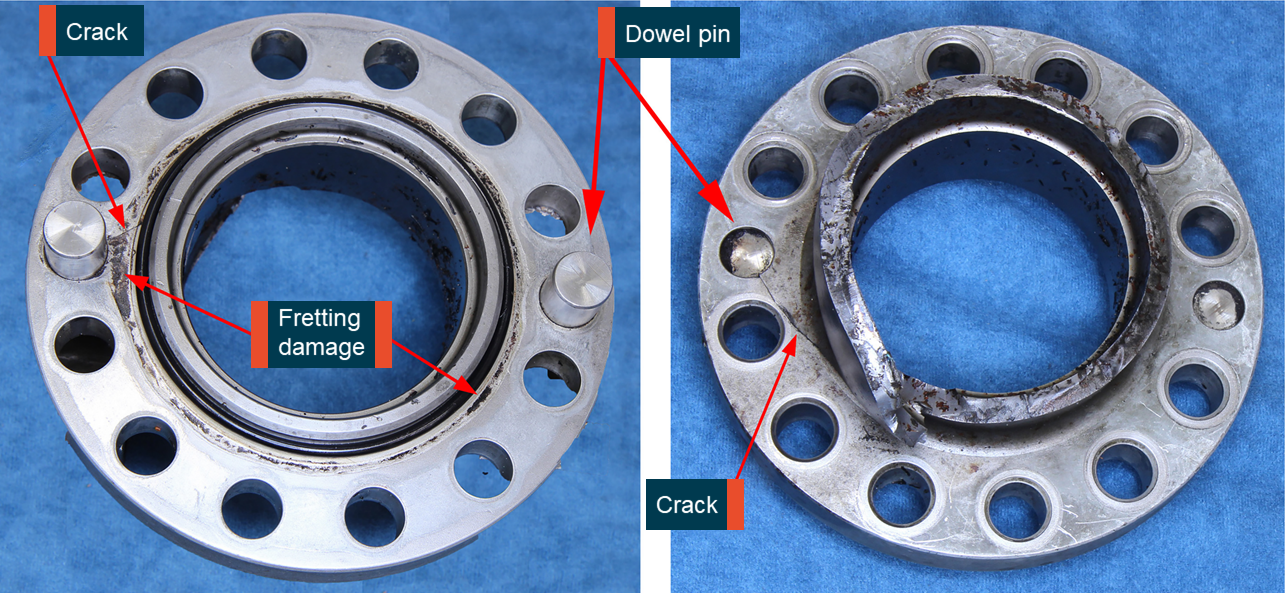
Image shows that cracking was observed near one of the dowel pins and the fretting discolouration observed on the propeller side of the flange. Source: ATSB
Examination of the propeller flange section of the fractured shaft revealed cracking emanating from one of the dowel pin holes (Figure 4). The cracking had progressed through the flange thickness, transitioning into the shaft portion at an angle indicative of torsional loading, and ultimately resulted in shaft separation. The shaft fracture had deformed in a radial direction, which exposed some of the fracture face, and evidence of beachmarks typical of fatigue (cyclic) cracking were observed (Figure 5).
Figure 5: Section of the exposed propeller shaft showing beachmarks
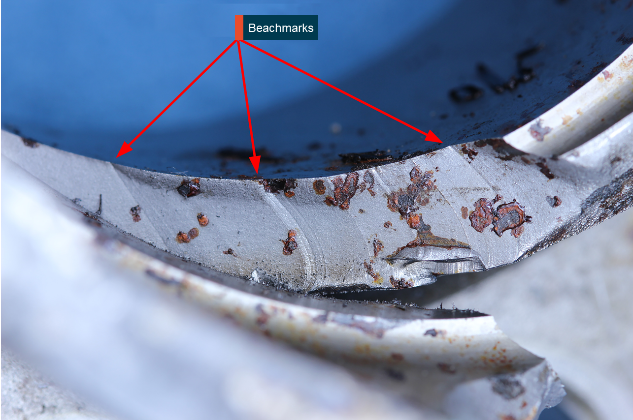
Image shows the beachmarks on the fracture surface, which was indicative of a fatigue failure mechanism. Source: ATSB
Local fretting damage and corrosion was observed around the forward flange surface circumference with the more severe damage observed directly inboard of the dowel pin hole at the crack location. Remaining flange thickness in the more heavily fretted region measured 0.684 inch (17.37 mm), which was 0.03 mm below the minimum manual limit requirement of 0.685 inch (17.40 mm). An oily dark residue was present around the retention lip feature of the dowel pin hole.
Similar shaped discoloration patterns to those observed on the propeller shaft forward flange were present on the gasket/shim; however, negligible wear was measured in these regions. Gasket/shim thickness measured 0.060 inch (1.524 mm) in two areas, indicating fretting wear on the steel propeller shaft likely occurred prior to the introduction of this particular gasket/shim. The gasket/shim is retained with the propeller during the removal/installation procedure, and the maintenance manual does not contain any information on when it is required to be changed. As such, there was no record of when this gasket/shim had been installed on that propeller.
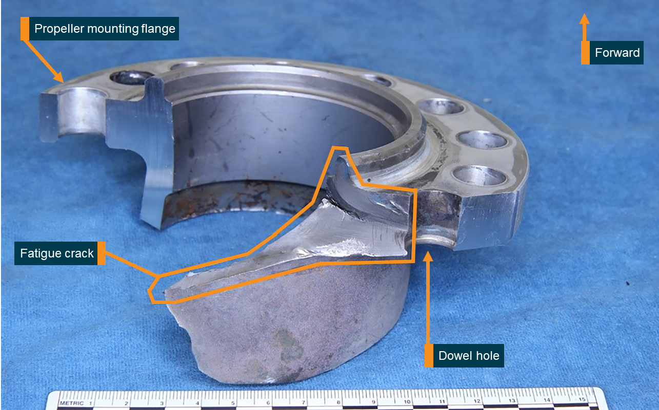
Following the initial visual examination, the sample was sectioned through the dowel pin holes in order to expose the fracture surface (Figure 6). Once opened, a discoloured initial fracture region consistent with fatigue was observed towards the forward flange face along with some discoloration of the dowel pin itself. The fatigue fracture itself had completely progressed through the flange thickness.
Figure 6: Section of the propeller shaft showing the fatigue crack progressing into the shaft
Source: ATSB
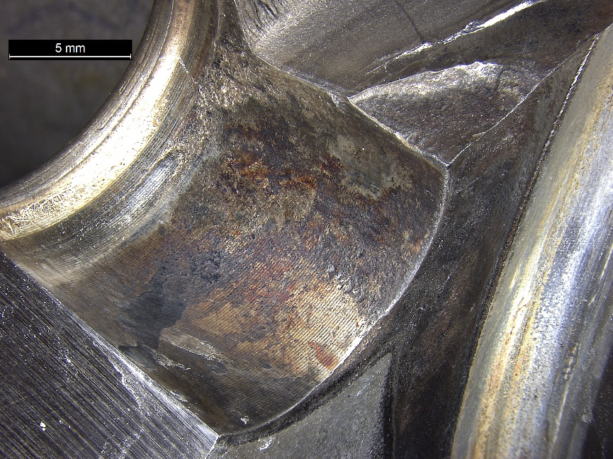
The dowel pin bore was corroded in parts (shown in Figure 7), and corrosion pitting was found near the fracture. Cadmium (Cd) plating, normally present on the forward flange face, dowel pin hole surfaces and exposed propeller shaft, was missing within the dowel pin hole, with the exception of several streaks near the aft end of the hole.
Figure 7: Corrosion observed within the bore of the dowel pin hole
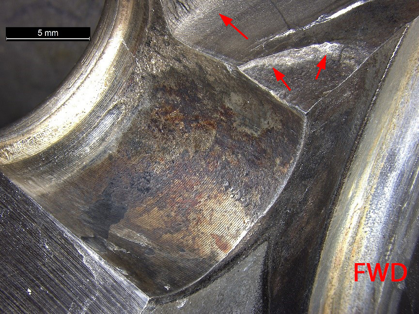
Image show corrosion in bore, along with crack originating at the forward corner of the dowel pin hole (arrowed) Source: ATSB
Manufacturer’s materials failure analysis
Following the visual examinations and preliminary sectioning at the ATSB facilities, the fractured components were returned to the engine manufacturer for additional analysis and testing. Examination in a scanning electron microscope confirmed the presence of corrosion product immediately below the initial fracture region along with shallow, trough-shaped features (Figure 8). Corrosion pitting was observed along the edge of the initial fracture leading to a rounded appearance. Spectral imaging (energy dispersive x-ray analysis) of the dowel pin hole and fretted region on the propeller shaft flange forward face also confirmed the absence of original cadmium (Cd) plating. The corrosion product consisted of iron (Fe), oxygen (O) (consistent with a steel corrosion product) sulphur (S) and residual cadmium (Cd).
Figure 8: Scanning electron microscope image of the internal surface of the dowel pin hole and initial fracture surface
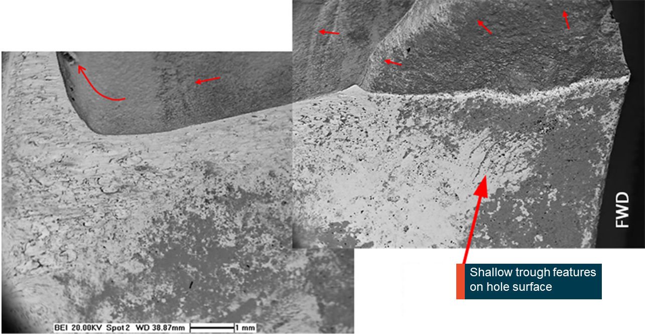
Source: GE
The propeller shaft flange was then sectioned to perform a microstructural examination of the fracture surface and the adjacent area. No microstructural anomalies were observed, and the microstructure was tempered martensite, consistent with the material type in the correctly processed condition. However, the metallographic sections showed significant general surface corrosion, pitting corrosion and secondary cracking in the area adjacent to the primary fracture surface. Many of the shallow secondary cracks identified during a step polishing examination were filled with corrosion product (Figure 9). The presence of multiple shallow crack features supported crack initiation towards the forward dowel pin hole area.
Figure 9: Metallographic cross section adjacent to the fracture surface showing secondary cracking
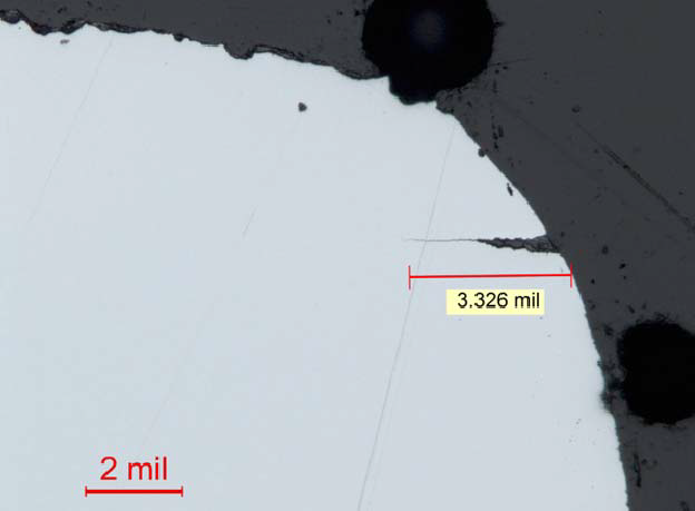
The micrograph shows the secondary cracking extending from the dowel pin hole in the region adjacent to the primary fracture surface. Also, note the corroded initial fracture surface at the top of the image, and the rounded fracture edge. Note that 2 mil is approximately equal to 50 µm. The crack length in the image is approximately 84 µm in length. Source: GE
Due to the badly corroded condition of the initial fracture surface, the engine manufacturer was unable to establish a definitive contributing factor for crack initiation. It was considered that corrosion within the dowel pin hole was a strong contributor. However, stress analysis performed by the manufacturer confirmed low alternating stresses in dowel pin hole area. For a flaw of 3.8mm x 3.8mm, with nominal assumptions, it was predicted that there would be no crack propagation. That is, corrosion pitting down to depth observed in the dowel pin hole on its own, would not cause crack propagation.
Mechanisms that would increase the dowel pin load such as loss of clamp between the flange faces could assist in crack initiation. While the torque values were not recorded during flange removal from the recovered propeller, bolt tensions were observed to be similar for all bolts and were consistent with expectations. Additionally, while the operator did not record torque values as part of their propeller removal process (nor were they required to per the propeller maintenance manual), they did not report experiencing any instances of low bolt tension during the propeller removal process.
The presence of that significant secondary corrosion did, however, support either an initially slower moving crack or a crack that had arrested for some unquantifiable period allowing the corrosion to occur. The remaining, less damaged portion of the fracture surface was consistent with lower alternating stress, high cycle fatigue (HCF) mechanisms, ultimately leading to shaft separation.
Propeller gearbox maintenance
Maintenance of the PGB propeller shaft was on-condition, meaning no mandated maintenance activities were specified, as it was a non-life-limited component. There were no records of shop visits for repair of PGB UDAG0153. There were also no records of animal strikes or propeller events.
The maintenance documentation did require ongoing inspection of the main propeller shaft whenever the gearbox was returned for maintenance. The GE maintenance manual SEI-576 72-10-00 also stated that whenever the propeller flange was exposed, for example, a propeller change, it was to be inspected for the following:
- nicks, burrs and scratches
- usable limits: any number, 0.15 inch (0.38 mm) deep maximum
- corrective action: remove high metal
- elongated holes
- usable limits: none allowed
- corrective action: replace gearbox
- dowel deformation
- usable limit: not permitted
- corrective action: replace gearbox
- missing cadmium plating on:
- forward face of the flange
- usable limit: any amount with no corrosion
- corrective action: replace gearbox
- forward face of the flange
- other locations
- not permitted, if base metal visible
- corrective action: repairable, brush with cadmium
- wear on the face of the flange
- usable limit: flange thickness at worn area must be 0.685 inch (17.40 mm) minimum
- corrective action: replace gearbox.
The most recent opportunity for the flange to be inspected was at a propeller change on 20 October 2016, approximately 5 months and 437 hours / 516 flight cycles prior to the occurrence. No rejectable issues were reported. The inspection was included in the operator’s propeller removal/installation worksheet, HM-26 Revision 5. One entry related to inspection of the flange, stated:
Carry out visual inspection of PGB propeller drive shaft flange (MRB 721003)
The worksheet contained a single box to be signed and dated at the completion of the task.
MRB 721003 was a task in the aircraft Maintenance Review Board report, which specified a ‘Visual inspection of the PGB propeller drive shaft flange during exposure at propeller maintenance’ and referred to GE MM SEI 576 72-10-00.
This particular PGB was subject to Airworthiness Directive AD 94-17-16 and Service Bulletin SB 72-A0350, Engine – General – Recommended Inspection of Propeller Shafts for Possible Inclusions. The service bulletin and supporting airworthiness directive required a one-time ultrasonic inspection of the propeller shaft flange outer diameter (OD) fillet radius and inner diameter (ID) bore to look for subsurface metallurgical defects on a suspect population of propeller shafts. The inspection was carried out on UDAG0153 on 8 February 1994 with no findings reported.
Propeller balancing
The manufacturer’s maintenance documents required a static balance of the propeller following overhaul (7,500 hours or 5 years) or major repair. The operator’s system of maintenance also required periodic dynamic balancing of propellers every 2,000-flight hours of operation. There was no requirement from the manufacturer to perform a dynamic balance upon installation of the propeller following an overhaul.
The occurrence propeller was statically balanced on 19 October 2016, at 1,361.8 hours since overhaul (TSO), as a result of fitment of a new de-ice boot. Following this maintenance activity, the propeller was fitted to PGB UDAG0153, which was installed on another company aircraft, VH-ZLX. The entire assembly (engine, PGB and propeller) was then moved to VH-NRX on 16 November 2016.
Other occurrences
The same propeller gearbox design was fitted to multiple variants of the CT7 engine (5A2, 7A1, 9B, 9C, and 9C3) on Saab 340 and EADS CASA[4] CN-235 aircraft. On 21 November 1991, a Comair Saab 340A aircraft experienced an in-flight propeller separation event near Buffalo, New York, United States. The National Transportation Safety Board (NTSB) examined that occurrence (NTSB No. NYC 92-I-A035) and concluded that the propeller shaft fractured as result of a fatigue crack that had initiated at an inclusion near the flange radius. Following the occurrence, GE mandated a fleet wide ultrasonic inspection to look for metallurgical inclusions at that location. They also changed the design of the shaft to include a larger radius at the fillet, which led to a reduction in stresses at that location.
__________
The in-flight loss of propeller involving Saab 340B VH-NRX at 19 km (10 NM) south-west of Sydney, New South Wales (NSW), on 17 March 2017, was the result of the fracture of the propeller shaft on the right engine propeller reduction gearbox (PGB). The shaft fracture led to the separation of the propeller from the aircraft. The flight crew performed an uneventful single-engine landing at Sydney Airport. The crew showed a high level of professionalism in their response to the engine failure and loss of a propeller. The crew demonstrated high levels of communication and coordination, and promptly applied checklists and procedures. As such, this analysis will focus on the failure of the propeller shaft.
Propeller shaft separation
The shaft failed as a result of a fatigue crack propagation that initiated at a dowel pin hole. The crack then propagated into the shaft in a torsional manner, before failing in overstress.
Extensive corrosion and fretting was observed on the PGB propeller shaft forward flange surface. The initial fracture surface adjacent to the dowel pin hole corner exhibited a darker surface from corrosion and debris product compared to the remaining fracture. The corroded condition of the initial fracture surface suggested the fatigue crack had been present for a significant period. However, the time from when it initiated could not be quantified. The portion of the fracture slightly beyond the heavily corroded region was smeared, but also exhibited significant pitting corrosion. Higher magnification examination in these areas revealed general fracture morphology consistent with lower alternating stress, high cycle fatigue (HCF) crack propagation mechanisms.
Due to the corroded condition of the initial fracture surface, a definitive root cause for crack initiation could not be established, although corrosion within the dowel pin hole was believed to be a strong contributor to crack initiation. Analysis by General Electric indicated that the initiation of fatigue cracking of the flange may be associated with a combination of factors that include:
- the accumulation of significant operational hours for the PGB
- the development of pitting corrosion damage within the dowel pin bore and at the front face of the propeller flange
- progressive wear and subsequent surface damage of the hub flange at stress-critical regions surrounding the dowel pin
- possible dowel pin load increase due to reduced clamping force.
Propeller gearbox maintenance requirements
At the time of the occurrence, there were no specific requirements in the manufacturer’s maintenance documentation for routine inspection within the dowel pin bores and cracking in that location. A failure in a similar location in 1991 prompted a one-off ultrasonic inspection for inclusions in the area, however, there were no ongoing inspections required.
While the maintenance manual did specify some general inspection and measurement of the propeller flange, there was no specific task to look for cracks, such as a magnetic particle or dye penetrant inspection. These techniques were only utilised when the PGB was disassembled for maintenance at a workshop specifically approved by the engine manufacturer. As such, any cracking or corrosion within the dowel pin hole may go undetected during routine maintenance.
Operator maintenance procedures
The operator was following the directions set out in the manufacturer’s maintenance documents. The operator demonstrated that they had previously rejected two PGB’s in 2007 and 2011 due to corrosion and missing cadmium plating on the propeller shaft and/or flange.
A single direction to inspect the PGB propeller drive shaft flange was included in the propeller removal/installation worksheet, HM-26 Revision 5, in accordance with the manufacturer's maintenance procedures. However, a number of deficiencies were identified in the worksheet, which meant the aircraft maintenance engineers may not have been given the best opportunity to detect a growing crack in the PGB shaft flange area. This is because:
- The worksheet referred to a visual inspection; however, the task in the maintenance manual was not solely a visual inspection. If wear was observed on the face of the flange, the flange thickness required measurement and it could be no less than 0.685 inch (17.40mm).
- The brief nature of the task description meant that there were no specific instructions on how the task should be carried out. For example, the method of flange thickness measurement was not specified on the form.
- There was no space on the worksheet to record any findings, such as recording the flange thickness measurements or if the cadmium (Cd) plating was worn and a repair required.
From the evidence available, the following findings are made with respect to the propeller separation event involving a 340B aircraft, registered VH-NRX (NRX), which occurred about 10 NM south-west of Sydney, New South Wales (NSW) on 17 March 2017. These findings should not be read as apportioning blame or liability to any particular organisation or individual.
Safety issues, or system problems, are highlighted in bold to emphasise their importance. A safety issue is an event or condition that increases safety risk and (a) can reasonably be regarded as having the potential to adversely affect the safety of future operations, and (b) is a characteristic of an organisation or a system, rather than a characteristic of a specific individual, or characteristic of an operating environment at a specific point in time.
Contributing factors
- The propeller shaft failed as a result of a fatigue crack that had initiated at the dowel pin hole and propagated through the shaft until it could no longer transmit the required loads.
- The engine manufacturer did not have specific inspection procedures in the maintenance documents of the propeller shaft to detect a fatigue crack originating from the dowel pin hole. [Safety Issue]
Other safety factors
- The form used by Regional Express during a propeller removal and installation, HM-26 Revision 5, included the task to inspect the propeller gearbox, but did not provide for recording of inspection findings as defined within documented procedures. Consequently, this did not provide for the best opportunity to ensure potential defects were identified, recorded and monitored.
Other findings
- The flight crew used checklist management and crew resource management effectively. These factors combined to contribute to a positive outcome for the aircraft.
- The ATSB and the engine manufacturer, General Electric, were unable to determine conclusively the reason for the fatigue crack initiation and propagation.
The safety issues identified during this investigation are listed in the Findings and Safety issues and actions sections of this report. The Australian Transport Safety Bureau (ATSB) expects that all safety issues identified by the investigation should be addressed by the relevant organisation(s). In addressing those issues, the ATSB prefers to encourage relevant organisation(s) to proactively initiate safety action, rather than to issue formal safety recommendations or safety advisory notices.
Depending on the level of risk of the safety issue, the extent of corrective action taken by the relevant organisation, or the desirability of directing a broad safety message to the [aviation, marine, rail - as applicable] industry, the ATSB may issue safety recommendations or safety advisory notices as part of the final report.
Lack of inspection method to detect fracture
Safety issue number: AO-2017-032-SI-01
The engine manufacturer did not have specific inspection procedures in the maintenance documents of the propeller shaft to detect a fatigue crack originating from the dowel pin hole.
Additional safety action
Whether or not the ATSB identifies safety issues in the course of an investigation, relevant organisations may proactively initiate safety action in order to reduce their safety risk. The ATSB has been advised of the following proactive safety action in response to this occurrence.
Regional Express
Following the occurrence, Regional Express (Rex) undertook a large number of actions, both in the immediate aftermath and as more information became available on the nature of the failure.
- Five aircraft with the same series PGB and shafts were immediately removed from service for further examination.
- The fleet-leader inspections of 12 nominated PGB’s were completed as per service bulletin SB 72-0530, by 16 June 2017.
- Inspections in accordance with service bulletin SB 72-0531 were completed on 14 February 2018 (71 inspections).
- The Rex Safety Management Group also approved completing the service bulletin inspection for all Rex fleet PGB’s that were outside of SB 72-0530 and SB 72-0531. As of 4 July 2018, Rex has completed a further 23 PGB inspections. On 28 February 2018, the FAA issued AD 2018-03-13, which was effective to the CT7 PGB and required the GE SB to be carried out on all PGB’s regardless of the TSN. Due to the existing propeller maintenance practices Rex had implemented and service bulletin scheduling in place, Rex was already compliant with the requirements of AD 2018-03-13. They also adjusted the scheduling of certain PGB inspections to match the AD compliance timeframe.
- The previous operator of the PGB was contacted to obtain historical details of operation and maintenance.
- During inspection of the propeller shaft in accordance with SB 72-0531, onsite training, including instruction from the manufacturer’s CT7 platform lead principal engineer, was conducted with line maintenance supervisors and other licensed aircraft maintenance engineers (LAMEs). In addition, computer based training (CBT) with specific reference to inspection of the propeller shaft was set up for all B1 LAMEs. The CBT will be recurring every 2 years.
- The operator performed a review of the maintenance practices for propeller removal/installation as described in their worksheets, HM-26, HM-27 and HM-15. As a result, the operator identified areas of improvement and changes to the worksheets have been implemented. The worksheets have been amended to include additional inspection steps for the PGB propeller shaft based on the latest GE service bulletin, SB 72-0531. A Notice to Engineers (NOTEM) was issued to all Saab Engineers on 3 July 2017 to advise them of the worksheet revisions.
- Established in-house capability to carry out the manufacturer's corrosion prevention process (cadmium (Cd) plating) through procurement of the necessary materials and equipment and training of engineering staff.
- An assessment of propeller balance maintenance practices were carried out and some modifications implemented including;
- Introduction of a periodic oil change task for the Hamilton Sundstrand[5] propeller hub.
- A requirement to carry out a dynamic balance on each occasion that a Hamilton Sundstrand propeller blade or hub is installed.
- Issuing instructions to engineers with a policy to achieve blade-shimming clearance at the lower end of the available range when installing Hamilton Sundstrand propeller blades.
- Initiation of a review of the propeller balance policy for the Dowty propeller.
Civil Aviation Safety Authority
The Civil Aviation Safety Authority conducted two audits on the operator following the event; the first was carried out from 3-11 May 2017; the second on 10-11 July, specifically looking at the propeller maintenance practices of the organisation.
__________
Sources of information
The sources of information during the investigation included the:
- flight crew
- aircraft operator (Regional Express)
- engine manufacturer (General Electric)
- aircraft manufacturer (Saab)
- Federal Aviation Administration (USA)
Submissions
Under Part 4, Division 2 (Investigation Reports), Section 26 of the Transport Safety Investigation Act 2003 (the Act), the Australian Transport Safety Bureau (ATSB) may provide a draft report, on a confidential basis, to any person whom the ATSB considers appropriate. Section 26 (1) (a) of the Act allows a person receiving a draft report to make submissions to the ATSB about the draft report.
A draft of this report was provided to Regional Express, Civil Aviation Safety Authority (CASA), General Electric, National Transportation Safety Board (NTSB), Saab, and the Swedish Accident Investigation Authority.
Submissions were received from Regional Express, CASA, General Electric and NTSB. The submissions were reviewed and where considered appropriate, the text of the report was amended accordingly.
Purpose of safety investigationsThe objective of a safety investigation is to enhance transport safety. This is done through:
It is not a function of the ATSB to apportion blame or provide a means for determining liability. At the same time, an investigation report must include factual material of sufficient weight to support the analysis and findings. At all times the ATSB endeavours to balance the use of material that could imply adverse comment with the need to properly explain what happened, and why, in a fair and unbiased manner. The ATSB does not investigate for the purpose of taking administrative, regulatory or criminal action. TerminologyAn explanation of terminology used in ATSB investigation reports is available here. This includes terms such as occurrence, contributing factor, other factor that increased risk, and safety issue. Publishing informationReleased in accordance with section 25 of the Transport Safety Investigation Act 2003 Published by: Australian Transport Safety Bureau © Commonwealth of Australia 2018
Ownership of intellectual property rights in this publication Unless otherwise noted, copyright (and any other intellectual property rights, if any) in this report publication is owned by the Commonwealth of Australia. Creative Commons licence With the exception of the Coat of Arms, ATSB logo, and photos and graphics in which a third party holds copyright, this publication is licensed under a Creative Commons Attribution 3.0 Australia licence. Creative Commons Attribution 3.0 Australia Licence is a standard form licence agreement that allows you to copy, distribute, transmit and adapt this publication provided that you attribute the work. The ATSB’s preference is that you attribute this publication (and any material sourced from it) using the following wording: Source: Australian Transport Safety Bureau Copyright in material obtained from other agencies, private individuals or organisations, belongs to those agencies, individuals or organisations. Where you wish to use their material, you will need to contact them directly. |


