What happened
On 19 November 2015, at about 1455 Eastern Standard Time (EST), a Jabiru J430 aircraft, registered VH-SZQ (SZQ), departed Kingaroy for Goondiwindi, Queensland (Qld). The pilot was the only person on board the private flight.
Earlier that day, the pilot had departed Bundaberg, Qld, where the aircraft engine had undergone maintenance that involved the installation of six new engine cylinder barrels and new piston rings. To ensure that the new cylinders barrels and rings would wear together to form a good seal, the pilot adjusted the engine RPM about every 15 minutes and closely monitored the engine oil pressure, oil temperature, cylinder head temperature (CHT) and exhaust gas temperature (EGT) gauges. Each of the six cylinders had a CHT and EGT sensor installed.
During the cruise at about 6,500 ft, and about 40 minutes after departing Kingaroy, abeam Dunmore, the pilot heard a noise coming from the aircraft engine, which then started to vibrate. The pilot moved the engine throttle control to the idle position, and about 8 seconds later the pilot heard a metallic noise and the engine stopped.
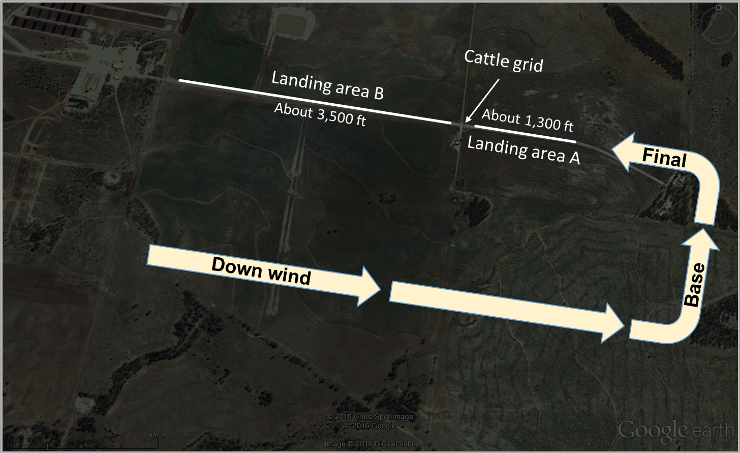
The pilot established the aircraft in a glide and looked for a suitable forced landing area. An airstrip was identified on an electronic world aeronautical chart (WAC), about 4 NM to the left of track, which the pilot initially navigated towards. The pilot was unable to locate the strip and subsequently turned towards a property where they could see people, houses, sheds and a highly visible white road (Figure 1).
Figure 1: Map showing the relevant features of the landing area

Source: Google earth, modified by the ATSB
At about 4,000 ft, the pilot selected a landing area on the road between the houses and a cattle grid (landing area A in Figure 2). SZQ entered on the downwind leg for a left circuit with the final approach towards the west. The pilot identified power lines close to the road (landing area A) and as they were unsure if they crossed the road, selected the road beyond the cattle grid as the land area (landing area B in Figure 2). The pilot completed the downwind and forced landing checks, and left the electrical master switch on to adjust the flap position when required.
At about 50 feet on final approach, the pilot was able to see that the power lines were far enough away from the road of landing area A that they would not be a hazard, and elected to land on the initial landing area selected. The pilot selected full flap and selected the electrical master switch off. The pilot side-slipped[1] the aircraft to descend quicker. Consequently, the pilot realised that the aircraft’s speed was too fast to land on landing area A and extended to the second landing area, landing area B, and climbed slightly to clear the cattle grid.
The left main landing gear collided with the grid and failed, partially remaining attached to the aircraft. The pilot flared for a landing and the left landing gear dug into the ground and swung the aircraft to the left. The aircraft subsequently collided with a fence and came to a stop about 100 m beyond the cattle grid. The pilot exited the aircraft. The pilot was not injured. The aircraft was substantially damaged.
Figure 2: Diagram representing the circuit pattern and landing areas

Source: Google earth, modified by the ATSB
Pilot comment
The pilot reported that there was thick smoke in the area from fires some distance away. The smoke only affected the horizontal visibility, which was reduced to 6 km. The wind was light with no obvious signs to determine the local wind direction. The temperature was about 28 ⁰C.
The pilot indicated that there was about 12 minutes from when the engine stopped to landing so they had time to analyse the situation. The pilot felt prepared for the forced landing due to the quality of the flight instruction they had received over the years. The pilot reported that no distress call was broadcast to air traffic control.
The pilot reported that prior to the departure from Bundaberg, three circuits were conducted in SZQ. After landing, maintenance personnel inspected the engine and no defects were reported. The pilot did not notice any issues with the engine prior to the failure.
The pilot indicated that the engine total time in service since new was about 756 hours and the time since a bulk strip/rebuild was about 187 hours.
Engine certification
The aircraft was an amateur-built Jabiru J430 and was operated as an experimental aircraft, issued with an experimental certificate. The original equipment manufacturer (OEM) (Jabiru Aircraft) manufactured the aircraft engine. The engine was installed on the aircraft in 2006 at the time of the aircraft build. In 2013 during an engine bulk strip/rebuild, part of the engine was modified with the installation of non-OEM parts resulting in the engine having a unique configuration. As the aircraft was an amateur-built aircraft, the original owner/builder certified for the installation of those parts. The annual inspection of the engine that was conducted prior to the most recent maintenance was conducted at an aircraft maintenance organisation.
Examination of the failed engine at the engine OEM
The failed engine was first examined at the engine OEM, and the Civil Aviation Safety Authority (CASA) was present at the examination. The engine examination identified the reason for the engine failure as a defect in the valve train where the valve head had made contact with the piston, resulting in significant secondary damage to the number 6 piston and cylinder. The three most likely reasons for the failure were identified by CASA as:
- The most recent maintenance event introduced a foreign body or dislodged existing deposits (of carbon) into the system, allowing debris to enter the valve guide/stem resulting in a sticking valve with the subsequent resulting damage of piston to valve contact.
- A sticking number 6 exhaust valve due to reduced clearances between the valve guide/stem. The effect of thermal expansion with non-OEM parts suggests that there is a possibility that original design clearances were not maintained.
- Incorrect clearances within the valve train, resulting in overheating of the valve stem and subsequent necking and cracking at the base of the stem, releasing the valve head into the cylinder. This was assessed as the least likely failure mode, as the levels of observed blackening (overheating) under the rocker covers was considered to be of a degree that would not result in this type of failure.
The examination concluded that the damage observed had the hallmarks of a sticking valve as opposed to a burned valve. Due to the substantial secondary damage destroying most of the evidence, an absolute conclusion could not be made.
Engine examination at the organisation that assisted in the last maintenance on the engine
The organisation that assisted the original owner/builder to bulk strip/rebuild the engine in 2013, and assisted in the most recent maintenance, conducted a second separate examination of the failed engine and noted the following:
-
- In 2013, the original owner/builder was provided assistance to bulk strip/rebuild the engine (builder assist bulk strip/rebuild), and some CAMit Aero Engine (CAE) components were installed. This did not include replacing the pistons.
- The maintenance immediately prior to the engine failure was to fit new CAE cylinder barrels and rings and engine oil inhibiting jets to the intake ports. The new owner (not the original owner/builder) advised that the engine EGT was too high and a different carburettor main fuel jet was installed.
- The number 6 cylinder failed resulting in the engine stopping.
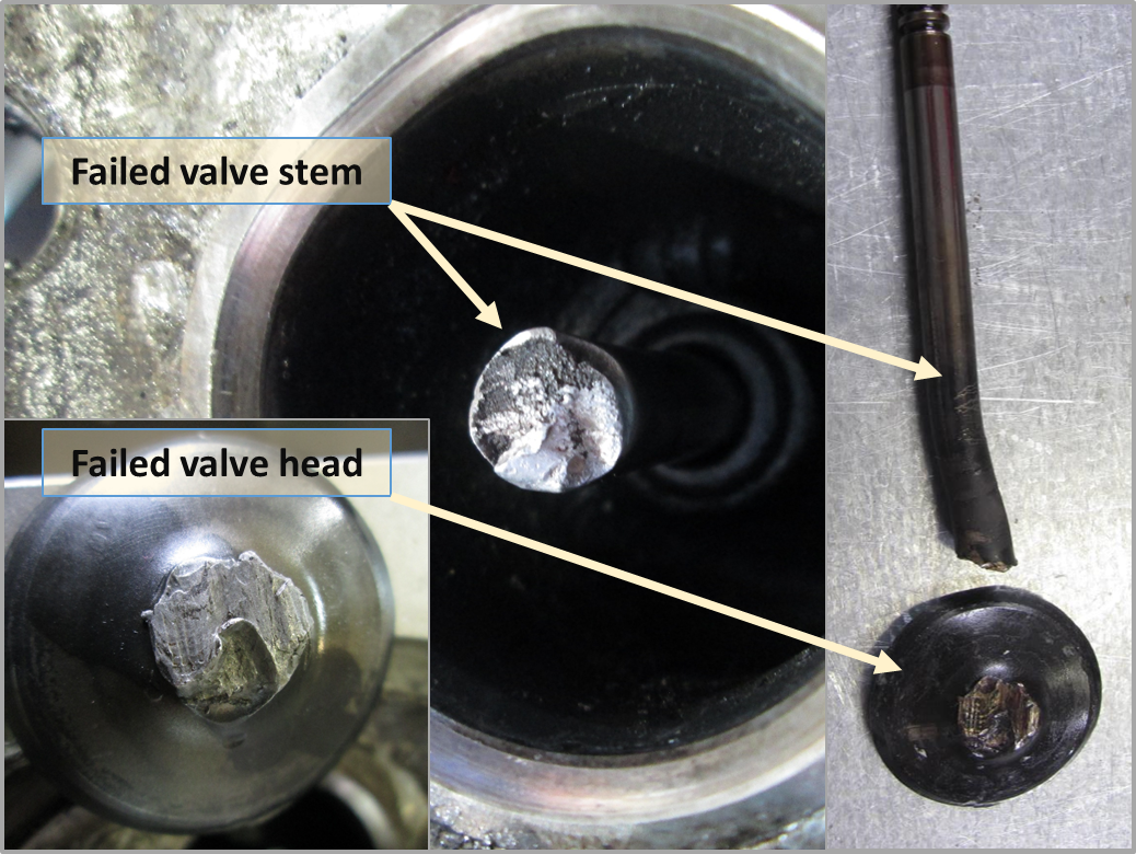
- The head of the number 6 exhaust valve was separated from the stem. The valve stem fracture area had severe mechanical damage after its separation but there was no sign of a fatigue fracture. The valve stem was ‘S’ bent in the semi-closed position which would indicate that the valve was not fully open when a possible mechanical collision with the piston was encountered. There was no evidence of significant heat damage to the valve stem (Figure 3).
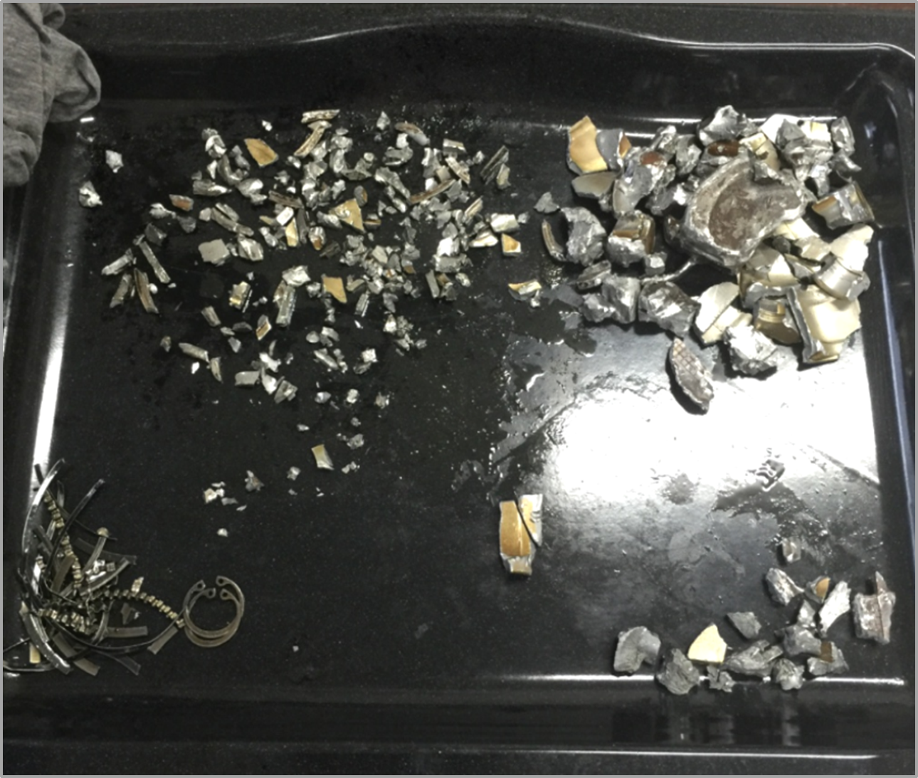
- The number 6 piston had completely dis-integrated (Figure 4).
Figure 3: Failed valve head and valve stem

Source: Organisation that assisted in the last maintenance, modified by the ATSB
Figure 4: Recovered parts of the number 6 piston

Source: Organisation that assisted in the last maintenance
- No damage was observed in the valve train such as bent pushrods or damaged rocker arms and adequate clearance was evident in the valve guide.
- It is possible that this engine had been run at a high EGT during maximum power settings since the engine bulk strip/ rebuild.
- Four small pieces of piston skirt were identified and showed signs that they were fractured before the failure. The shiny, peened surface of the fracture faces appeared to indicate cyclic compressive forces to a crack surface during engine operation.
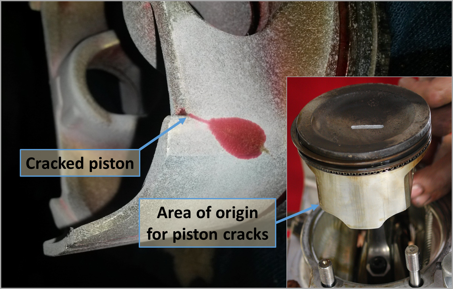
- An inspection of the remaining pistons for evidence of cracks revealed that the five other pistons were also cracked before the engine failed (Figure 5). The cracks all initiate at a stress raiser between the piston skirt and the piston-pin boss web. This stress raiser is machined into the piston during original manufacture for jigging purposes.
- It is most likely that an initial partial failure of the number 6 piston skirt allowed piston debris to lodge between one side of the head of the valve and the valve seat. The next stroke of the piston would then collide with the partially closed valve bending the valve head about the obstruction and generating enough leverage to fracture the head off the valve stem; initiating the final destruction of the cylinder components.
- The high EGTs reported would indicate that detonation[2] could have been encountered on multiple occasions, which would apply excessive stress at the stress raisers on the piston skirts.
Figure 5: Location of crack detected in all five pistons and example of crack location shown on a piston assembly

Source Organisation that assisted in the last maintenance and CASA, modified by the ATSB
Engine fuel type
The owner reported that the aircraft’s engine had been operated for a period of time on Australian premium unleaded motor spirit (MOGAS) of 95 RON (Research Octane Number). A little while prior to the accident, the owner identified a Jabiru service letter Alcohol, Lead, Compression Ratio: Fuel Guidance JSL007-6 effective date 12 August 2015 and has since only been using Australian aviation gasoline (AVGAS). The service letter is applicable to experimental models, in all models and variants of Jabiru engines and is available from the Jabiru website.
The service letter discussed that when burning a fuel in a piston engine, one of the most important characteristics of the fuel is how much load it can take without detonation. Detonation results in excess temperature and pressure in the engine and in extreme cases can break pistons or cause other damage very quickly. The service letter notes that operators use MOGAS at their own risk and recommends where possible the use of AVGAS. AVGAS is a fuel specifically designed for aircraft use and is subject to very strict documentation and quality assurance. The vast majority of MOGAS blends have lower octane ratings and are therefore less resistant to detonation than AVGAS blends. Many automotive MOGAS blends rely on highly volatile components. During storage, those volatiles can be lost rapidly and the fuel’s performance can degrade significantly in a relatively short period. The service letter notes that it is possible for MOGAS to lose several points from its octane rating while stored, leaving the engine vulnerable to detonation.
The organisation that assisted in the last maintenance indicated that it is possible that light detonation on previous flights may have overstressed the piston at the stress raiser and initiate a fatigue failure of the number 6 piston. The examination of the engine pistons and cylinders did not extend to analysing the combustion deposits for evidence of detonation from previous flights.
Safety action
Whether or not the ATSB identifies safety issues in the course of an investigation, relevant organisations may proactively initiate safety action in order to reduce their safety risk. The ATSB has been advised of the following proactive safety action in response to this occurrence.
Organisation that assisted in the last maintenance
As a result of this occurrence, the organisation that assisted in the last maintenance has advised the ATSB that they are taking the following safety actions:
- All CAE pistons will be modified to minimise the stress raiser that was found in the non-CAE pistons installed on SZQs engine, which will reduce the detonation sensitivity of the pistons.
- A survey of CAE engine owners will be conducted asking questions relating to their engine EGTs to gauge the risk of similar failures.
- Maintenance advice to check all reused pistons for cracks and to modify the stress raiser will become standard practice.
- A test engine has been subjected to similar conditions to enable more accurate failure mode analysis in the future.
Safety message
Pilots should consider the effect an in-flight engine failure at different altitudes has on the time available to manage that failure and identify a suitable forced landing area. In this instance, the pilot had about 12 minutes from the engine failure to landing and was able to consider the options, with enough time to manoeuvre towards a different area (road on property) when the first was not suitable. Regularly updating forced landing options during a flight is particularly important in the event of a time critical situation.
CASA Flight Safety Australia magazine July-August 2007 article Emergency: staying in control is available from the CASA website. The article discusses that reporting an emergency is important when time permits, just in case not everything goes to plan. It is not an inconvenience: it’s what air traffic controllers are trained and qualified to do. They are skilled in dealing with emergencies and providing professional appropriate assistance. Where emergency situations arise, an early in-flight emergency notification will assist in expediting the desired outcome – a safe landing.
The accident also highlights the importance to owners and operators to remain aware of information published by the aircraft and engine manufacturer.
The ATSB has recently published an analysis of reported engine failures: Engine failures and malfunctions in light aeroplanes (AR-2013-107) and is available from the ATSB website. That report found that over the six years between 2009 and 2014, there were 322 engine failures or malfunctions involving single-engine piston aeroplanes up to 800 kg maximum take-off weight. Valve train related fractures were one of the most common failures found.
Aviation Short Investigations Bulletin - Issue 49
Purpose of safety investigationsThe objective of a safety investigation is to enhance transport safety. This is done through:
It is not a function of the ATSB to apportion blame or provide a means for determining liability. At the same time, an investigation report must include factual material of sufficient weight to support the analysis and findings. At all times the ATSB endeavours to balance the use of material that could imply adverse comment with the need to properly explain what happened, and why, in a fair and unbiased manner. The ATSB does not investigate for the purpose of taking administrative, regulatory or criminal action. TerminologyAn explanation of terminology used in ATSB investigation reports is available here. This includes terms such as occurrence, contributing factor, other factor that increased risk, and safety issue. Publishing informationReleased in accordance with section 25 of the Transport Safety Investigation Act 2003 Published by: Australian Transport Safety Bureau © Commonwealth of Australia 2016
Ownership of intellectual property rights in this publication Unless otherwise noted, copyright (and any other intellectual property rights, if any) in this report publication is owned by the Commonwealth of Australia. Creative Commons licence With the exception of the Coat of Arms, ATSB logo, and photos and graphics in which a third party holds copyright, this publication is licensed under a Creative Commons Attribution 3.0 Australia licence. Creative Commons Attribution 3.0 Australia Licence is a standard form licence agreement that allows you to copy, distribute, transmit and adapt this publication provided that you attribute the work. The ATSB’s preference is that you attribute this publication (and any material sourced from it) using the following wording: Source: Australian Transport Safety Bureau Copyright in material obtained from other agencies, private individuals or organisations, belongs to those agencies, individuals or organisations. Where you wish to use their material, you will need to contact them directly. |
__________
- Flight manoeuvre where the flight path is inclined downwards and there is a steady loss of height without significant change in airspeed. The longitudinal axis of the aircraft is markedly displaced from the flightpath.
- Detonation is the uncontrolled explosion of the fuel/air mixture in the combustion chamber of a piston engine cylinder, as distinct from an even and progressive burning. Light to medium detonation may result in some mechanical damage.


