Sequence of events
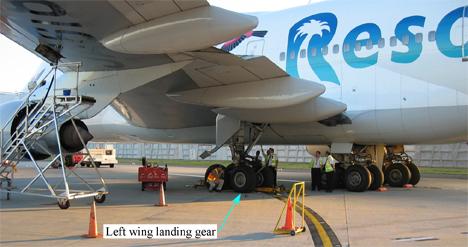
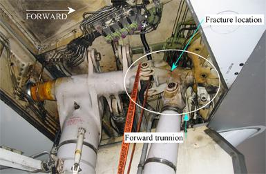
At about 1200 Eastern Standard Time on 30 May 2005, a Boeing Co 747-300 (747), registered JA8184, was being pushed back from its gate at Sydney International Airport for a scheduled passenger flight to Osaka, Japan. During pushback, the ground staff heard a loud cracking noise. The pushback was stopped and an inspection by the ground crew identified a structural failure in the left wing landing gear forward trunnion fork (trunnion), as shown in Figure 1 and 2. After an on-site inspection by the Australian Transport Safety Bureau (ATSB), the aircraft was moved to a hangar for maintenance and the fractured component was removed from the aircraft and sent to the ATSB for a detailed examination.
Figure 1 : Left wing landing gear
Figure 2: Looking up and outboard into wing landing gear well
Examination of fractured trunnion
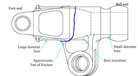
The trunnion had sustained a complete through-section fracture, located approximately mid-way between the ball-end and the fork-end (Figure 3).
Figure 3 : Fracture location on trunnion
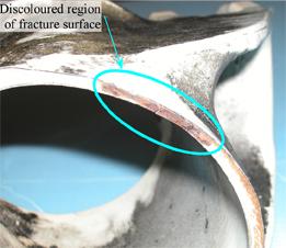
A general inspection of the fractured trunnion revealed a discoloured (orange/brown) region on the fracture surface (Figure 4) in the upper outboard region. The corroded nature of that region, compared with the adjacent bright fracture surfaces, indicated the presence of a pre-existing defect, and that the trunnion had been cracked for a period of time prior to the final failure during the pushback.
Figure 4 : Fracture surface
The fractured component was examined in a metallurgical laboratory under the supervision of the ATSB. Chemical analysis of a sample taken from the trunnion near the fracture showed that the material met the specification for AISI/SAE 4340M alloy steel. Metallographic examination confirmed a fine-grained lightly tempered martensitic microstructure, typical of the 4340M alloy in the hardened and tempered condition. The inner and outer surfaces were also observed to have been finished with a metallic type plating and painted with a surface primer and topcoat.
Hardness measurements taken indicated that the material had an ultimate tensile strength of approximately 275,600 psi (1900 MPa).
Wall thickness measurements taken around the fractured trunnion circumference showed that the minimum local wall thickness of 0.137 inches (3.48 mm) corresponded with the corroded and discoloured area of cracking.
A detailed technical examination of the corroded region identified two transverse fatigue cracks originating at the inner surface of the trunnion bore (noted as C1 and C2 in Figure 5). The cracks had initiated approximately 11mm apart and had joined to form a single crack. This crack continued to grow until the final fracture occurred during the pushback.
Figure 5 : Fatigue crack development
Crack C2 presented well defined fatigue progression marks, including several distinct regions of fatigue and corrosion (Figure 6). The region bounded by the red dotted line was a distinct region of heavily corroded fatigue cracking and was about 4 mm long and 1.6 mm deep.
Figure 6 : Fatigue progression and corrosion marks
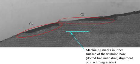
Close examination of the origins in the inner wall of the trunnion found that crack C1 had initiated from multiple closely spaced origins at the root of a machining groove, giving the appearance of a longer crack following the machining groove (or mark). Crack C2 had also originated at the root of a machining groove from multiple closely spaced origins, but over a much smaller distance before aligning with the principal stress plan1, resulting in the apparent difference in the planes of the cracks as shown in Figure 7. The plane of the initial cracks in both C1 and C2 were approximately parallel and were aligned with the machining grooves in the inner surface.
Figure 7 : Plane of crack origins
The inner and outer surfaces did not have a consistent surface roughness. Well defined machining marks were observed in the large diameter bore and to a lesser extent on the small bore. However, the outer surface and the taper region in the bore were relatively smooth without defined machining marks. The well-defined machining marks on the large and small diameter bore blended into the smoother surface of the taper region (that is, there was no abrupt change in surface roughness).
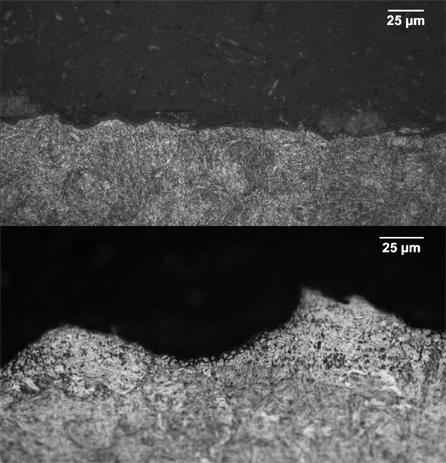
Examination of the surface microstructure in the region of the cracks revealed that the smooth regions (outer surface and taper section) had a thin layer of deformed material typical of a cold working process such as shot peening2. The area of surface deformation in the taper region ran out just before the radius (a few millimetres from the cracks). Figure 8 shows the differences in the surface roughness at a microscopic level (scale is 25µm, or 0.025 mm).
Figure 8 : Smooth surface (upper); surface with distinct machining marks (lower)
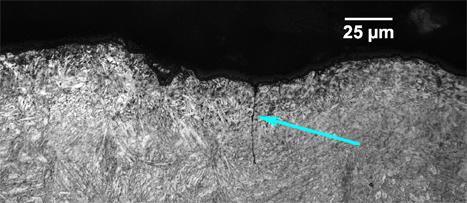
The sections taken from adjacent to the primary cracks for micrographic examination contained multiple independent fatigue cracks of various sizes. One example is shown in Figure 9. Each of these cracks originated in the root of the machining groove and were associated with shallow intergranular penetrations, which also existed in the roots of the machining grooves (Figure 8).
Figure 9 : Secondary fatigue crack indicated by arrow
Component manufacture
The landing gear trunnion was manufactured to the aircraft manufacturer's specifications by an approved external supplier. Both the supplier and the aircraft manufacturer informed the ATSB that the trunnion was manufactured at some time prior to 1975; however, the original manufacture documentation (including the manufacture plan and conformance records) was destroyed in 1994. The trunnion specifications were supplied by the aircraft manufacturer. Those documents included construction drawings and process specifications.
In the trunnion specifications, the aircraft manufacturer specified the use of 4340M steel, heat treated to an ultimate tensile strength of 275,000 to 300,000 psi. Therefore, the material used in the manufacture of the failed component met the steel alloy and strength requirements of the design.
The minimum allowable wall thickness specified3 for the trunnion at the location of the failure was 0.180 inches (4.57 mm). Therefore, the minimum wall thickness measured at the crack of 0.137 inches (3.48 mm) was 0.043 inches (1.09 mm) thinner than the design allowed.
Component maintenance
The maintenance documents supplied by the aircraft operator indicated that the trunnion had been fitted to five aircraft and had amassed a total of 25,095 landing cycles during its service life. The records also showed that the trunnion had been overhauled by the operator's component repair workshop on four occasions (Table 1). The landing gear assembly had an overhaul interval of 8 years or 12,000 cycles, whichever occurred first. Therefore, the landing gear was not due for overhaul for another 4 years, or 9,509 cycles.
Table 1 : Overhaul history
Overhaul |
Date |
Total cycles at overhaul |
| 1 |
October 1979 |
3,517 |
| 2 |
November 1987 |
14,069 |
| 3 |
March 1992 |
16,508 |
| 4 |
October 2001 |
22,604 |
The overhaul records showed that on each occasion, the trunnion had undergone repair work. The documents indicated that the repairs were limited to the lugs and were within the repair limits permissible by the aircraft manufacturer. There was no record of any repair work carried out in the bore of the trunnion or on the outer surface in the region of the bore diameter transition.
Comparison of the overhaul instructions maintained by the operator with those supplied by the aircraft manufacturer confirmed that the operator's workshop maintained the correct instructions for the overhaul. The overhaul instructions for the component did not require a dimensional check for wall thickness or a specific check for surface finish (roughness) in the bore.
As one of the first processes in the overhaul, the protective finishes (including metallic plating) were removed from the surface of the trunnion. These finishes are removed using a chemical process, some of which, including water for cleaning, can have a corrosive effect on the trunnion material.
The overhaul procedure for the landing gear components required that the component undergo a magnetic particle inspection (MPI) to detect any defects, including cracks, that may have developed during service. The manufacturer did not provide specific instructions on how to perform the MPI on this particular component but provided a general process that the operator was to use as the basis for a component specific process. Neither the overhaul procedure nor the MPI process directed the MPI technician's attention to the radius in the bore diameter transition as a possible location for cracking. The MPI process used was capable of highlighting cracks of less than 0.5mm.
The overhaul records provided by the operator indicated that an MPI of the component was carried out at each overhaul. The MPI procedure defined by the operator was in accordance with the aircraft manufacturer's recommended procedure. It used the equipment and materials recommended by the manufacturer and specified sufficient examinations to highlight any cracks in the component. The overhaul records indicated that the item had been found satisfactory on each occasion, suggesting that no cracks had been detected.
The component maintenance manual for the repair of high-strength steel landing gear parts directed the operator to obtain advice from the manufacturer if cracks were detected during the MPI. The manufacturer did not have a record of any request for advice relating to the failed component.
The crack was in a location that was not readily viewable during a normal visual ground check. There was no requirement to perform a detailed inspection for cracks in the body of the trunnion between overhauls.
- The principal stress plane is a plane that the stress in the part acts perpendicular to. In this case, the principal stress plane was not aligned with the machining marks.
- Shot peening is a process where small 'shot' beads are fired against the surface of a component producing a residual compressive surface stress and a thin layer of deformed material. This process has been demonstrated to increase the fatigue life of high-strength steel components.
- In the manufacture drawings for the component.


