At 0803 Western Standard Time on 24 April 2005, an Airbus Industrie A340-212 (Airbus) aircraft, registered ZS-SLA, with a crew of 11 and 219 passengers, landed short of the displaced threshold on runway 21 at Perth Airport, Western Australia. The aircraft was on a scheduled flight from Johannesburg, South Africa. The pilot in command was the handling pilot for the approach and landing at Perth.
At 0803 Western Standard Time on 24 April 2005, an Airbus Industrie A340-212 (Airbus) aircraft, registered ZS-SLA, with a crew of 11 and 219 passengers, landed short of the displaced threshold on runway 21 at Perth Airport, Western Australia. The aircraft was on a scheduled flight from Johannesburg, South Africa. The pilot in command was the handling pilot for the approach and landing at Perth.
The displaced threshold was required during Stage 3 of works involving the reconstruction of runway 06/24 and taxiway intersections at Perth airport. On 1 December 2004, the airport operator issued Method of Working Plan (MOWP) YPPH 01/04 which described the proposed works. The MOWP was distributed to air operator users of Perth Airport, including the operator of the Airbus.
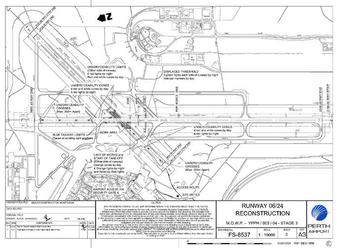
The MOWP provided information that Stage 3 works included reconstruction of the runway 03/21 intersection. The Stage 3 works were scheduled between 0130 and 0930 on each programmed workday. During the Stage 3 work periods, the threshold of runway 21 was displaced 1,331 m to the south, and the glidepath component of the runway 21 instrument landing system was not available. A temporary precision approach path indicator (PAPI) was also installed on the eastern side of runway 21 to provide visual guidance for a 3-degree approach to the touchdown zone for the displaced threshold. The temporary PAPI was 395 m to the south of the runway 21 displaced threshold. Refer to Appendix A for a diagram of the displaced threshold arrangements for Stage 3 of the works.
The PAPI system consisted of a bar of four light-emitting units adjacent to runway 21. Each unit of a PAPI system produces a light beam that is divided into an upper white and a lower red sector. A pilot sees the four individual lights in a combination of red and white depending on his vertical position in relation to the approach slope. If an aircraft is descending on the correct approach slope, a pilot will see red beams of light projected from the two inner boxes, and white beams projected from the two outer boxes. If the aircraft is too high in relation to the approach slope, the pilot will see white beams of light projected from all four boxes. Conversely, if the aircraft is too low in relation to the approach slope, the pilot will see red beams of light projected from all four boxes.
The MOWP included information that visual ground aids associated with the works would be supplied, marked, and located in accordance with the Civil Aviation Safety Authority (CASA) Manual of Standards Part 139 Aerodromes.
CASA also published a Manual of Operational Standards. Part 3 of that manual related to aerodromes, and included the following advice in the introductory material relating to the marking of displaced thresholds:
During a landing approach, a pilot attempts to create a standard approach situation using information from, among other things, cockpit instruments, glideslope guidance and runway aspect and markings. When a pilot sees the runway picture he/she expects to see during his/her scan of these inputs, any unobtrusive temporary markings outside his/her normal areas of concentration may not cue him sufficiently to make him react to them. Temporarily displaced threshold markings must compete with normal threshold markings, centreline markings, fixed distance and touchdown zone markings, visual glidepath information and all the other visual inputs which tend to guide a pilot to a touchdown zone close to the approach end of the visual runway. These existing cues must be disrupted and the temporary markings made obvious enough to direct the pilots attention to the displaced threshold.
Paragraph 3.3.1.1 of the CASA Manual of Operational Standards stated that temporarily displaced thresholds on runways that do not display permanent threshold markings shall be marked by V-bar markers on each side of the runway. During the Stage 3 works, four red and white cone-shaped unserviceability markers were placed over the threshold markings, and four red and white cone-shaped unserviceability markers were also placed across runway 21, immediately to the north of the intersection of taxiway D with runway 21. Four unserviceability crosses were placed on runway 21 between the permanent threshold and the intersection of taxiway D. Unserviceability crosses were also located adjacent to the runway between the intersection of taxiway D and the intersection of runway 06/24. The portion of runway 21 between the intersection of taxiway D and the displaced threshold was available for aircraft to taxi to the take-off point. That portion of the runway surface was not marked with unserviceability crosses. There were, however, unserviceability crosses adjacent to the shoulders of that portion of the runway.
The MOWP included details of the notice to airmen (NOTAM) to be issued for each stage of the works. The works safety officer was responsible for initiating the appropriate NOTAMs, through the Australian NOTAM Office, 48 hours before the commencement of a particular works stage. The Stage 3 NOTAM included details of the linear displacement of the threshold of runway 21, and that the displaced threshold would be marked by five green lights on either side of the runway and also with V-bar markers. The NOTAM included information that the runway 21 glidepath was not available. It also included information about the location of the temporary PAPI, that the temporary PAPI would be set to Stage 2 intensity, and that 5 minutes notice would be required to change the intensity of the PAPI. There were no requests made to alter the intensity of the PAPI setting during the aircrafts approach to runway 21.
The Airservices Australia Manual of Air Traffic Services contained information on the intensity of precision approach lighting systems. Stage 2 was the preferred initial selection for fine, night, overcast conditions. Stage 4 was the preferred initial selection for fine, day, overcast conditions, while Stage 6 was the preferred initial selection for bright, clear, day conditions.
The pre-flight NOTAM briefing package supplied to the crew of the Airbus before the departure from Johannesburg included the NOTAM relating to the Stage 3 runway 21 displaced threshold at Perth.
At about 4,000 ft during the descent into Perth, the air traffic controller cleared the crew to make a visual approach to runway 21. The crew subsequently reported that, although they were aware of the displaced threshold, they could not identify the displaced threshold markings during the approach. The crew asked the aerodrome controller to confirm the location of the displaced threshold, and the controller advised the crew that it was to the south of the intersection of runway 06/24. The pilot in command adjusted the approach flight path accordingly. The crew then observed what they perceived to be a transverse white line across the runway just to the north of the intersection of runway 06/24. Because the perceived line was close to the intersection of runway 06/24 referred to by the controller, the crew assumed the line to be the displaced threshold. The crew observed that the runway was clear of machinery and personnel, and the pilot in command landed the aircraft just past the perceived transverse line.
As the aircraft passed over the perceived line, and just before touchdown, the pilot in command saw that the perceived line consisted of cone-shaped unserviceability markers. The actual touchdown point of the aircraft was about 670 m short of the displaced threshold delineated by the V-bar markers on each side of the runway, and 1,065 m from the temporary PAPI touchdown area (refer Appendix A). The crew subsequently reported that at no stage during the approach did they see any other markings that delineated the displaced threshold. They also reported that they could not distinguish the V-bar markers referred to in the NOTAM.
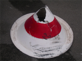
The aircraft ran over one of the red and white cone-shaped unserviceability markers during the landing (see figure 1). However, the aircraft was undamaged, and there was no other damage.
Figure 1: Damaged cone-shaped boundary marker

There was 10 km visibility at Perth at the time of the occurrence, with 7 oktas (7-eights of total sky visible to the celestial horizon) of stratocumulus cloud at 5,000 ft above mean sea level.
Two days after the occurrence, the aerodrome operator amended its procedure for daytime opening of the displaced threshold on runway 21. The amended procedure included a requirement for the temporary PAPI to be set to Stage 6 intensity when the runway lights were turned off at first light.
The ATSB received no other reports of aircraft landing short of the displaced threshold on runway 21 at Perth during the period in which the Stage 3 works were conducted.
The visual ground aids associated with the Stage 3 works were marked and located in accordance with the Civil Aviation Safety Authority (CASA) Manual of Standards Part 139 - Aerodromes and the CASA Manual of Operational Standards. The notice to airmen (NOTAM) relating to the Stage 3 works included details of the displacement of the threshold of runway 21 and its associated markings, and included information that the runway 21 glidepath was not available. It also included information about the location of the temporary precision approach path indicator (PAPI), and that that it would be set to Stage 2 intensity.
The crew of the Airbus were aware of the displaced threshold, but seemed uncertain about its extent. Their perception that the unserviceability cone-shaped markers were a line signifying the displaced threshold was probably heightened by the fact that it was beyond the area of runway surface that was marked by unserviceability crosses. Additionally, as no unserviceability crosses were located on the runway beyond that point, it may have led the crew to assume that the aircraft could be safely landed beyond the cone-shaped unserviceability markers, even though there were no V-bar markers on each side of the runway to indicate that was actually the case.
Glideslope guidance was available from the temporary PAPI. The fact that the aircraft landed short of the displaced threshold meant that the landing approach was below the correct approach slope to the touchdown point associated with the displaced threshold. That being so, the temporary PAPI should have provided appropriate visual cues to the crew that the aircraft was below the intended approach slope. It is likely that the crew did not notice the PAPI because they were uncertain about the exact location of the displaced threshold, and were therefore not looking far enough down the runway to notice the PAPI light beams. Additionally, the PAPI was only set to Stage 2 in fine, daylight, overcast conditions, when Stage 4 was the optimum setting for those conditions. Under those circumstances, the light beams emitted by the PAPI may have been inconspicuous to the crew and outside their area of concentration in attempting to determine the location of the displaced threshold.
In this occurrence, the temporarily displaced threshold markings and the light signals from the temporary PAPI on the Stage 2 setting, were not of sufficient salience to compete with the other visual inputs to the crew. Consequently, the crew inadvertently misidentified the position of the displaced threshold.
Appendix A: Stage 3 works at Perth Airport


