At 0825 local time on 10 March 2005, a Bell 212 helicopter with three crew and five passengers departed Wallaby landing zone near Moliana, East Timor to conduct an aerial survey of the island. Prior to the flight, the passengers requested that the cabin sliding doors be secured in the open position for better observation. At approximately 0935, while tracking along the coast at 90 KIAS at approximately 800 ft AGL, the flight crew reported that they experienced a bump to the helicopter similar to air turbulence. A subsequent control and instrument check did not reveal any problems. The rear crewmember then informed the pilot in command (PIC) that the right cabin sliding door had fallen off. The PIC elected to conduct a precautionary landing in a nearby field. Following the landing, damage to the right side of the tail boom and horizontal stabilizer was noted and the door recovered for examination.
The Australian Transport Safety Bureau examined the sliding door attachment hardware to determine if there were any pre-existing faults of the components.
Examination of the aircraft and wreckage revealed that the forward roller support of the passenger door had fractured. The part had no specified safe life.
1.1 Assembly information
Two parts were recovered from the forward door assembly, the forward roller support and the mating serrated plate.
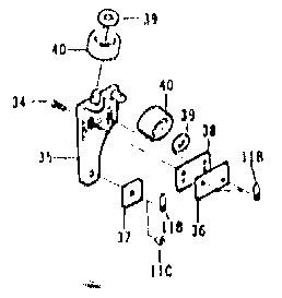
The forward roller support (35), illustrated in figure 1, is located inside the passenger compartment of the helicopter and is one of four roller attachments of the passenger door to the upper track. When the door is in the open position, this attachment carries the entire load of the passenger door. Elliptical holes through the support and its attachment to the mating serrated plate (38) via screws (34), allow the door to be located between the upper and lower roller tracks.
Figure 1: Forward Door Support Assembly.
1.2 Visual Examination
1.2.1 Forward Roller Support
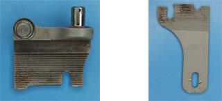
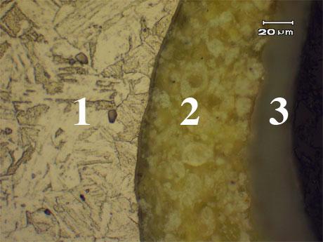
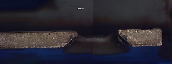
The forward roller support was recovered in two sections shown in figure 2 as A and B. The fracture of this part extended through the serrated area of the support, 45mm from the top of section A and intersecting with the elliptical locating holes. The support was painted with a chromate primer and a grey top coat, together approximately 100µm thick.
Figure 2: Section A of the forward roller support (left) and Section B of the forward roller support (right).
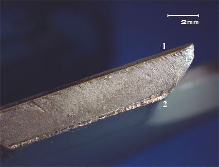
The fracture surface revealed striations and ratchet marks, consistent with fatigue failure. Part of the fracture surface of section B, shown in figure 3, reveals ratchet marks occurring at the serrated edge of the support (1) and final fracture at the back edge of the support (2). This is consistent along the entire fracture surface.
Figure 3: Fracture surface of section B, ratchet marks are visible at the serrated edge of the part (1) and the final fracture of the back edge of the part (2).
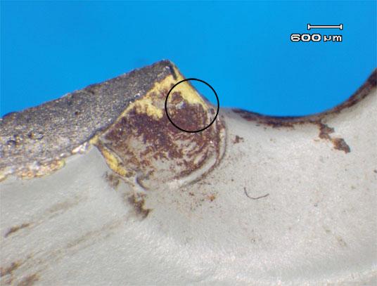
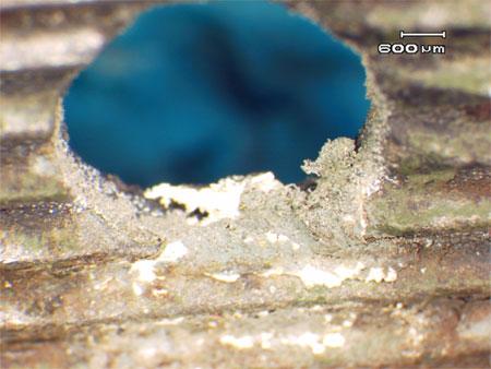
Iron oxide deposits were also observed on sections A and B. Location of the oxide coincided with the mating surfaces of the forward door assembly and the serrated plate and between the elliptical holes and the locating screws. Close examination of the elliptical holes revealed the paint layer was pleated as shown in (figure 4). The location of these pleats coincided with the positions of locating screws. Further deterioration of the paint layer was also observed in this area, leaving the yellow primer exposed.
Figure 4: Oxide products within the elliptical holes of section B. Note the top coat deterioration and pleating (circled) revealing the chromate primer layer (yellow).
1.2.2 The Serrated Plate
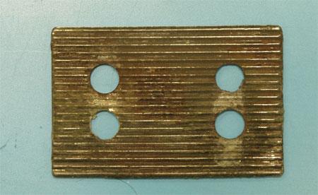
The serrated plate attachment, shown in figure 5, was not painted. Iron Oxide and fretting of the holes were observed, shown in figure 6.
The screws that attached the roller support and serrated plate to the passenger door were not recovered for this investigation.
Figure 5: The serrated plate.
Figure 6: Fretting around holes in the serrated plate. Iron oxide products are also visible.
1.3 Metallographic Examination
A segment of the forward roller support including the fracture surface and serrations was removed from section B. The representative sample was prepared and examined to characterise the materials general microstructure.
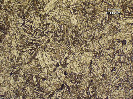
The material which exhibited magnetic properties, revealed a microstructure typical of a Precipitation Hardened (PH) Stainless Steel . PH Stainless Steels are often used in the aircraft and aerospace industries due to superior hardness and corrosion resistance. The martensitic type microstructure revealed by this sample, shown in figure 7, is typical for this material.
Figure 7: Microstructure of the forward roller support material (10X magnification).
Figure 8: The metal (1), primer (2) and top coat layer (3) interfaces (10X magnification).
Vickers hardness tests were carried out using a 20kg load, a total of five tests returned a mean value of 323 HV. These hardness results are typical of PH stainless steels.
FRACTURE CHARACTERISATION
Using light microscopy, the fracture surface of section A revealed the part had failed in fatigue. Crack initiation was identified as occurring on both sides of the right screw hole, circled in figure 9, and more clearly shown in figure 10. Ratchet marks at the serrated edge of the support indicated that crack progression occurred in the direction arrowed in figure 9, and through the thickness of the part. Rapid, unstable fracture characterised by a brighter fracture surface was also observed, shown in figure 11.
Figure 9: Fracture surface of section A. Crack initiation sites are circled and crack propagation directions are indicated with arrows (6X magnification).
Figure 10: Crack initiation sites, section A (6X magnification).
Figure 11: Rapid, unstable fracture surface, section A. Note the brighter appearance of the fracture surface (6X magnification).


