1. FACTUAL INFORMATION
1.1. Examination brief
During a climb to a new cruise level with maximum climb thrust set, the flight crew of a scheduled passenger service Boeing 747-338 aircraft noted an increase in vibration from the number 3 engine, accompanied by warning indications from the engine monitoring instrumentation. The engine was shut down and the flight continued to its destination.
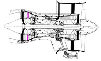
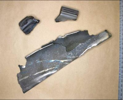
Subsequent engineering examination of the RB211-524D2 engine (serial number 12682) revealed the failure of a single blade from the low-pressure turbine second stage (LPT-2, figure 1). Sections of the failed blade, including the root block, and portions of the separated airfoil section were recovered from the engine and forwarded to the Australian Transport Safety Bureau (ATSB) for examination (figure 2).
Figure 1: RB211-524 engine profile showing location of LPT-2 blades (coloured)
Figure 2: Blade fragments recovered from the failed engine
1.2. Visual characterisation
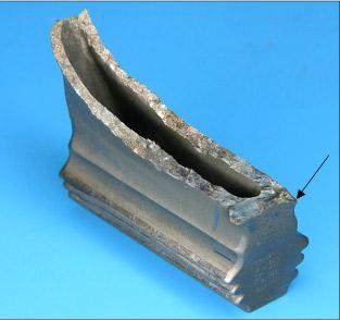
The part number LK83851 stage-2 low-pressure turbine blade (serial number TA6939B) had fractured through the base of the airfoil section; the fracture path extending diagonally from just above the dovetail transition at the rear face, to a position approximately 33 mm above the blade base, measured along the forward face (figure 3).
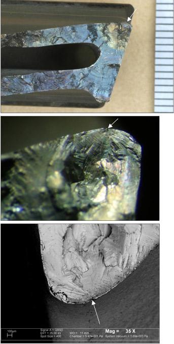
Figure 3: LPT-2 blade root section showing the fracture profile and its point of origin (arrowed)
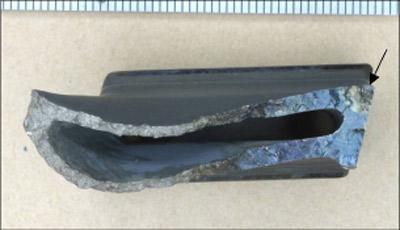
The entire fracture was confined to the region beneath the blade platform and airfoil section transition. The fracture surface morphology confirmed a progressive fatigue cracking mechanism (figure 4), with optical and electron microscopy identifying a single origin approximately 790 µm from the rear face of the root block (figures 5 - 7).
Figure 4: Plan view of the blade fracture showing the fatigue cracking morphology and point of initiation
Figures 5 - 7: Blade fracture at increasing magnifications with origin identified
Other than mechanical damage attributable to the loss of the outer blade section, the blade root block showed no evidence of external tool marks, handling damage or other physical features that could be held as contributory to fatigue initiation.\
The blade root block carried the embossed and engraved identification:
Trailing edge face: C2179 1H1153 < 22>
Leading edge face: LK83851 TA6939B < 9> < 13> < 29> < 201>
The engine manufacturer confirmed that the numbers represented as <xx> above indicated the application of various repair schemes during prior blade overhaul/s. On review, none of those schemes contained actions involving activity at or in the vicinity of the fatigue origin. The manufacturer also indicated that the engraved (vibro-etched) markings '< 201>' had been placed closer to the shank edge than allowed by the particular repair scheme, and that markings too close to section corners have the potential to adversely affect the blade integrity. In this instance however, the cracking showed no association with the < 201> marking, or any other similar feature.
1.3. Metallography & micro-analysis
A serial grind-polish-examine process was used to investigate and characterise the features at and surrounding the fatigue origin. The plane of grinding was parallel to the trailing edge root block face and a total of four metallographic planes were examined through the origin area. A fractured and intrusive dark oxide-like material inclusion was observed during the second stage of examination (figure 8).
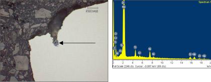
Figure 8 and 9: Metallographic cross-section through origin and EDS spectra of inclusion present at arrow
Energy dispersive x-ray analysis (EDS, figure 9) of the inclusion identified a range of elements from the typical base metal chemistry (Ni, Nb, Ti), as well as zirconium (Zr) which was foreign to the base metal alloy but later identified as a component of the refractory moulding material used during the investment casting of the turbine blades. Dimensionally, the visible sections of the inclusion measured approximately 40 µm in the major dimension, with the engine manufacturer indicating that the maximum root defect dimension allowable by the relevant quality acceptance standards (QAS) was in the order of 508 µm (0.2").
The general blade microstructure was typical of a cast nickel-based high temperature alloy, with massive semi-script form carbides within a solid-solution (?, gamma) matrix.
1.4. Chemical analysis
Spectrographic analysis techniques identified the base LPT blade alloy as an IN713LC nickel-chromium-aluminium-molybdenum material. The engine manufacturer confirmed this as the intended LPT blade alloy.
1.5. Fatigue loading and operating conditions
The initiation of fatigue cracking within any component is an indication that the magnitude and number of local stress cycles sustained have exceeded the limits of the material at the crack origin. Components such as the LPT-2 blades that do not have a prescribed fatigue life limit are engineered such that the nominal and expected transient design stresses and stress cycles are kept below the threshold for fatigue initiation. Where fatigue cracking does initiate in these items, it is, by implication, an indication that either the component has been subject to general stresses above the design limits, or that some anomaly has acted to locally concentrate the stresses in the affected area. The presence of notches, tool marks, physical defects, inclusions or microstructural abnormalities can all lead to local stress concentration effects, thus providing conditions suitable for fatigue crack initiation.
In the analysis of previous LPT-2 blade failures, the engine manufacturer had implicated uneven fuel distribution issues in the excitation of blade vibration sufficient to produce high-cycle fatigue cracking. In this instance however, there was no reported evidence from the engine examination to suggest that fuel distribution or combustion conditions had been problematic, or that those conditions had contributed to the blade failure.
2. ANALYSIS
The LPT-2 blade fracture morphology indicated that failure had resulted from a progressive high-cycle fatigue (HCF) mechanism, initiated from a surface or near-surface inclusion at the rear trailing corner of the blade root section. The inclusion chemistry and morphology suggested its origin from the refractory mould used to cast the blade during initial manufacture.
Given that inclusions and other entrained discontinuities are inherently difficult to avoid in components produced by casting processes, limits are conventionally placed on the size and location of such features to maintain the structural integrity of the items under static and dynamical loading conditions. In this instance, although the dimensions of the visible portion of the inclusion were below the manufacturer's allowance for discontinuities of that nature, it was possible that the defect in total may have been considerably larger, being broken up and partly lost during the blade fracture and separation.
3. CONCLUSIONS
The following conclusions were drawn from the examination of the failed LPT-2 blade from RB211-524D2 engine serial number 12682.
1. Blade failure resulted from the initiation and growth of a fatigue crack from the rear trailing corner of the blade root section.
2. Physical evidence suggested the initiation of cracking from a casting inclusion formed during blade manufacture.