Examination of a failed helicopter tail rotor shaft coupling assembly, Kawasaki Heavy Industries 47G3B-KH4
1 FACTUAL INFORMATION
1.1 Investigation brief
Accident event
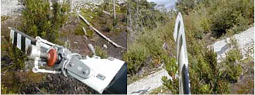
On 27 September 2004, as the Kawasaki KH 4 helicopter was approaching to land, the pilot reported that the helicopter commenced an uncommanded right yaw motion that could not be arrested by tail rotor control inputs. Upon increasing power, the rate of yaw and rotation also increased, with the helicopter revolving approximately five times before the pilot reduced power and main rotor collective, allowing the helicopter to settle to the ground where it rolled onto its right side. The three occupants exited the helicopter, having sustained minor injuries.
Examination
During the post-accident investigation of the helicopter, the owner reporting finding the tail rotor drive shaft fractured at the point where it adjoined the forward coupling. The tail rotor had impacted the ground, however the damage sustained by the blades showed no evidence of rotation under power. The fractured drive shaft and both forward and rear couplings were recovered from the accident site by the aircraft owner and submitted to the Australian Transport Safety Bureau (ATSB) for technical examination to assist in the investigation of the occurrence.
1.2 Inspection
Coupling design
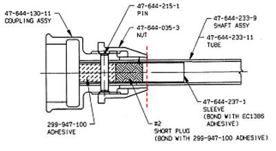
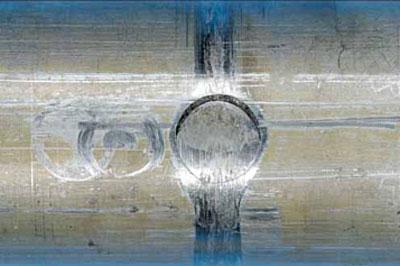
The helicopter tail rotor coupling assembly employed a tapered clamping nut arrangement bearing upon the outer circumference of the shaft tube. For rigidity in the clamped locations, an internal sleeve was fitted and secured with adhesive injected between the sleeve and tube bore. A single machine pin passed transversely through the coupling, tube and sleeve to provide for the positive positional security of the components. Figure 11 illustrates the assembly as a sectional view.
Figure 1: Tail rotor drive shaft coupling, point of failure indicated
Forward coupling and shaft fracture
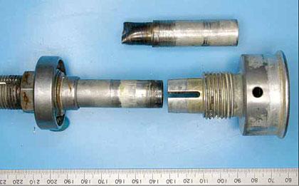
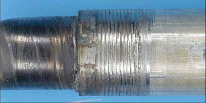
Upon initial receipt, the tail rotor drive shaft was confirmed as failed and separated at the point where it entered the forward coupling socket assembly (refer to figure 2). The fractured end of the shaft remained within the coupling, requiring removal by boring of the securing through-pin ends and pressing of the shaft stub out of the coupling (refer to figure 3).
Figure 2: Forward drive shaft coupling after disassembly
Figure 3: Drive shaft stub after removal from coupling
The failure of the securing through-pin at both protruding ends (refer to figure 4) was evident after removal of the shaft stub. The morphology of both fractures was typical of ductile shear overload under transverse loading (shaft twisting) conditions.
Figure 4: Fractured through-pin from the forward coupling. Note also the scoring from post-fracture rotation of the shaft
Figure 5: Spiral scoring on the gripped section of the shaft, adjacent to the fracture
Circumferential scoring of the shaft surfaces to either side of the through-pin indicated subsequent rotation of the shaft inside the coupling after separation. The shaft had fractured approximately 48 mm from the coupling end, exposing the end 18mm of the internal reinforcing sleeve. The last 12 mm of the shaft before the fracture showed deep spiral scoring where the tapered grip segments normally clamped upon the surface (refer to figure 5). The shaft fracture surfaces had been marred and damaged by continuing contact after separation and presented no appreciable evidence of the failure mode (refer to figure 6).
Figure 6: Damaged shaft fracture surface
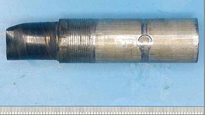
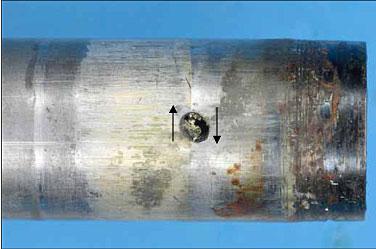
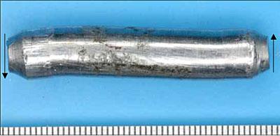
Figure 7: Torsional distortion of the drive shaft adjacent to the point of failure. Note the elongation of the small hole
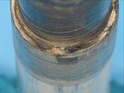
The opposing fracture and section of the shaft that extended from the forward coupling (refer to figure 7) showed extensive scoring, discolouration and galling, consistent with the damage noted inside the taper coupling bore (refer to figure 8). The examination also noted the torsional distortion of the material around a small adhesive bleed hole in the shaft wall (refer to figure 7 also). In a similar manner to the opposing section, the fracture surface had been heavily damaged by post-failure interference and presented little information of value.
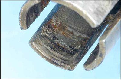
Figure 8: Extensive galling and metal adhesion inside the clamping section of the forward coupling
Rear coupling
The rear tail rotor drive shaft coupling was a similar design to the forward unit. The rear coupling showed no significant evidence of slippage of the shaft within the clamped section. The securing through-pin had not failed, however upon removal it presented with appreciable opposing axial bending around the points where the pin passed through the assembly (refer to figure 9).
Figure 9: Through-pin removed from the rear coupling, showing axial distortion typical of a significant torsional overload
2 ANALYSIS
The ATSB examination confirmed the failure and separation of the tail rotor shaft at the point of engagement with the forward drive coupling, approximately 48 mm from the forward end of the shaft. While the shaft fracture surfaces were damaged beyond allowing any interpretation of the original failure mode, the twisting and distortion of the tube material at either side of the fracture was evidence of the shaft having sustained transient torsional overloading conditions. Similarly, the shear failure of the coupling through-pin and the subsequent shaft rotation inside the coupling was a further indication that the assembly had carried, or sustained torsional loads of a magnitude well above the design allowable limits. Mirroring the torsional overload along the load path was the distorted through-pin from the rear coupling.
On the basis of the damage sustained by the forward coupling and engaged shaft, it was evident that the failure had proceeded in two distinct stages. Initially, the transient torsional overload event had overcome the clamping friction and caused the shear failure of the through-pin on the forward coupling. Once the pin had failed, the shaft was then able to slip and rotate within the coupling, where it was likely that the galling damage generated between the coupling bore and shaft surface led to the 'screwing' action that pulled the shaft further into the coupling and produced the surface damage that ultimately led to the shaft fracture at that point. While the fracture surfaces were damaged, it was probable that the shaft fracture mode was one of ductile torsional shear. The transverse plane of fracture supports this.
Contributory events
During normal flight and ground operation, the helicopter tail rotor shaft should not sustain any transient torsional loads beyond those imposed by normal engine power changes and/or tail rotor pitch movements. To produce the overload failure and damage to the coupling pins, the tail rotor system must have at some time, been exposed to conditions or events capable of producing a significant increase in the rotational resistance of the assembly. Gross mechanical failures within the tail rotor gearbox, tail rotor impacts, or drive shaft bearing seizures remain as possibilities in that regard.
The reported loss of tail rotor effectiveness and the absence of rotational damage to the tail rotor upon ground impact was consistent with the drive shaft coupling slippage and rotation developing during the landing approach. While the coupling pin failure must have been a precursor to the slippage, there was no physical or reported evidence to suggest when that failure may have occurred or what events may have contributed to it.
3 CONCLUSIONS
On the basis of the investigation findings, the following conclusions could be drawn:
- The helicopter tail rotor drive shaft had sustained damage consistent with a significant torsional overload event and subsequent rotational slippage and separation of the shaft at the forward coupling.
- The accident scenario and damage sustained was consistent with the slippage and separation of the shaft during the helicopter's landing approach.
- The factors contributing to the initial overload event could not be conclusively established.
- Diagram provided by Kawasaki Heavy Industries Ltd, assembly reference 47-640-052-39 (Shaft Assembly)