FACTUAL INFORMATION
At 1435 Eastern Standard Time on 10 August 2004, a Boeing Company 717-200 aircraft, registered VH-VQA, was climbing to cruise altitude on a scheduled passenger service from Melbourne, Vic. to Hobart, Tas. with six crew and 52 passengers on board. As the aircraft passed through flight level (FL) 110, the crew heard a loud bang, with a corresponding increase in indicated left engine vibrations. The left engine began to spool down and the turbine gas temperature (TGT) indications began to increase significantly.
The crew initially brought the left engine power lever back to idle. However, the TGT continued to increase, indicating a maximum of 1,149oC, before they shut the engine down and discharged a fire bottle into the cowling area in accordance with the operator's procedures. They then notified Melbourne air traffic control (ATC) of the engine failure and returned to Melbourne.
The operator examined the left engine and found metal fragments in the exhaust area and some metallisation1 of the exhaust duct.
At the time of the failure, the BR700-715 engine, serial number 13148, had completed 10, 321 hours and 8,888 cycles since new, and 6,474 hours and 5,417 cycles since repair.
Engine investigation
The operator removed the engine and forwarded it to the engine manufacturer in Germany for detailed investigation, under the supervision of a representative of the German Federal Bureau of Aircraft Accident Investigation (BFU2), on behalf of the Australian Transport Safety Bureau (ATSB).
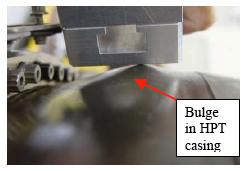
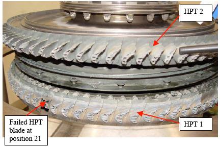
The manufacturer conducted a visual inspection of the engine's exterior, noting a bulge around most of the circumference of the high-pressure turbine (HPT) casing (Figure 1), in line with the Stage-1 HPT (HPT 1). A borescope examination of the engine interior showed that one HPT 1 blade was almost completely missing, with the remaining HPT 1 blades separated just above the blade platforms (Figure 2). There was also significant damage to the subsequent HPT and low-pressure turbine stages. Examination of the engine's compressor assembly revealed no significant damage. All of the high energy debris from the failure had been fully contained3.
A detailed examination of the engine revealed that the reason for the engine failure was the release of a single HPT 1 blade. The blade failed following the development of low-cycle fatigue4 (LCF) cracking in its internal cooling passages. All other engine damage was considered to be a consequence of the initial HPT 1 blade failure.
Figure 1: Bulged HPT casing
Figure 2: Damage to HPT 1 and HPT 2 rotors
Blade design considerations
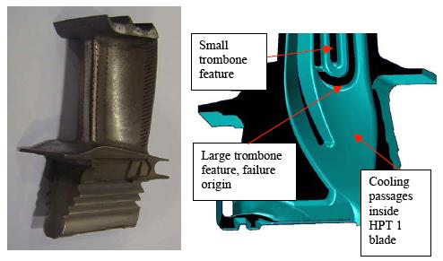
The failed HPT 1 blade (Figure 3) was a life improvement package5 (LIP) blade. The blade was a shrouded-tip aerofoil design, with multi-passage internal cooling (Figure 4). There was a vapour aluminised coating on the blade's external aerodynamic surfaces and internal cooling passages.
The manufacturer indicated that there have been four similar failures of LIP HPT blades in the BR700-715 engine type, with another engine failure still under investigation. One failure occurred prior to this event in November 2003. The remainder occurred after this incident.
Figure 3: The failed HPT 1 blade (position 21)
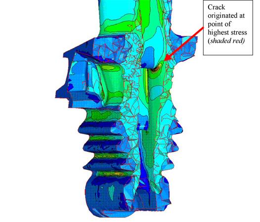
Following those failures, the manufacturer conducted additional computer stress modelling on the LIP blades. That modelling found that there were stress levels in the larger trombone radius feature, within the blade's cooling passages (Figure 4) that were potentially in excess of the manufacturer's original design intent. The manufacturer also found that the thickness of the vapour aluminised coating inside the blade's internal cooling passages was variable and difficult to predict. In certain operational conditions, dependent upon high strains in areas of stress concentration and local temperature, the coating could crack with the possibility of subsequent growth into the coated (parent) material. The area from which the failure occurred was confirmed to be the most susceptible to this behaviour (Figure 5).
Figure 4: Intact HPT 1 blade (left); blade internal cooling passage showing trombone feature (right)
Figure 5: Computer generated stress diagram from the manufacturer indicating the point of potentially excessive stress and crack origin
Flight data recorder information
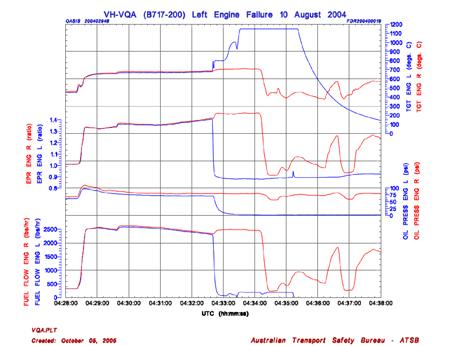
The ATSB's examination of the aircraft's flight data recorder (FDR) for the occurrence flight found that the left engine had surged as the aircraft passed through 10,240 ft. The engine pressure ratio (EPR) and engine rotational speed indications decreased abruptly, while the turbine gas temperature (TGT) for the engine began to increase. HPT vibration values for the engine increased from a level of 0.5 units before the failure to a maximum of 6.3 units over a three-second period. The manufacturer's high-limit for vibrations was 4.0 units.
The FDR readout indicated that the TGT for the engine continued to increase following the engine failure and remained at an indicated maximum of 1,149oC for 1 minute and 46 seconds before decreasing (Figure 6). It is likely that the maximum TGT reached during the failure was higher than 1,149oC, however the aircraft systems do not record above that temperature.
The FDR report indicated that there were no anomalies observed in the performance of the left engine prior to the failure.
Figure 6: FDR data plot of key engine parameters at the time of the failure
- Metal pulverised by the turbine becomes molten and flows rearward attaching to the subsequent turbine and exhaust assemblies (US Department of the Air Force (1987). Safety Investigative Techniques (AF Pamphlet 127-1, Volume II. Washington DC: Author).
- Bundesstelle für Flugunfalluntersuchung (BFU).
- FAA AC 33-5, paragraph 5.c. definitions state '…Contained means that no fragments are released through the engine structure, but fragments may be ejected out of the engine air inlet or exhaust'.
- Fatigue that occurs at relatively small numbers of cycles. Brooks, C. (1993). Metalurgical Failure Analysis. USA: McGraw-Hill, Inc.
- The Life improvement Package 3 (LIP3) was a suite of HP Turbine modifications that included the HPT blade P/N BRH20351. The manufacturer introduced the package by SB-BR700-72-100801.