Factual Information
On the morning of 18 June 2004, a Saab 340 aircraft, registered VH-KEQ, with a crew of three and 31 passengers, was being operated on a regular public transport flight from Albury to Melbourne, Vic. The pilot in command (PIC) had levelled the aircraft at flight level (FL) 120 (12,000 ft) with indicated air speed (IAS) and half bank selected on the autopilot. The engine anti-ice system and propeller and airframe de-ice systems were activated.
The PIC reported that the outside air temperature was -10 ºC, while the IAS was 145 to 150 kts. As the PIC increased the propeller RPM to aid with ice shedding, the IAS rapidly decreased to 137 kts. The PIC disconnected the autopilot and initiated a descent to 10,000 ft. During the autopilot disconnection, the stick shaker activated for about 1 to 2 seconds. The PIC reported that there were no autopilot miss-trim indications during the event. Ice was still present on the aircraft radome after landing.
The stall warning system fitted to the Saab 340 consists of two independent dual channel stall warning computers, left and right angle of attack sensors, two stick shakers and a stick pusher. The system provides five distinct warnings of an impending stall, commencing with stick shaker and aural clacker, followed by autopilot disengage, a visual warning in the form of stick pusher initialisation lights on the instrument panel, and a stick pusher.
The stall warning computers receive inputs from separate angle of attack sensors that are situated on the forward section of the fuselage, which measure airflow relative to the fuselage. Activation of the wing de-ice system increases the angle of attack signal by 0.4 degrees to increase the stall margin by 1 to 2 kts when the de-ice boots are inflated.
The stall warning computer activates the stick shaker at 12.5 degrees angle of attack and the stick pusher at 19 degrees angle of attack, with zero flap deflection and wing de-ice systems deactivated. Activation of the stick shaker causes the autopilot to disengage. Initiation of this warning for both pilots occurs when either of these sensors reaches the predetermined angle of attack. The stick pusher command requires a stall warning output from both sensors, while one or both sensors is required for stick pusher in the event of stall identification.
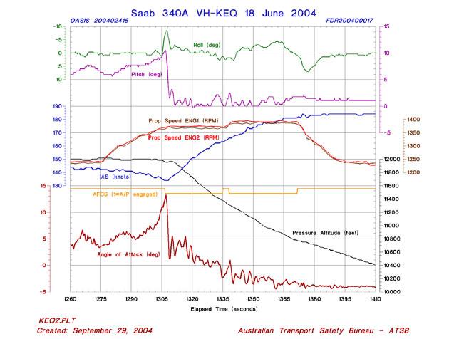
Following the incident, the data from the aircraft's flight data recorder was downloaded and analysed by the Australian Transport Safety Bureau (ATSB). The data indicated that from the time the aircraft levelled at FL120, the autopilot was maintaining that flight level by providing nose-up elevator movement and automatically re-trimming. At the same time, the IAS was decreasing and the angle of attack was increasing. About one minute later, the RPM of the propellers began to increase from 1,240 RPM to 1,370 RPM. However, over the same period, torque values decreased from 73 to 65 percent and the IAS continued to decrease.
About 1 minute later, with an IAS of 134 kts, the angle of attack reached the value required for stick shaker activation and the autopilot was disconnected. However, because of the disconnection, the subsequent nose-down elevator movements are considered to have been in response to control inputs from the crew, thus the angle of attack did not reach the value required for operation of the stick pusher (19 degrees).
No airframe buffet was evident in the recorded lateral, longitudinal or vertical acceleration data for this event. Recording limitations (sampling rates and the accelerometer frequency response) mean that light buffeting may have occurred and not been evident in the recorded data.
The stick shaker and subsequent control inputs from the crew were initiated before a loss of control of the aircraft.
Recorded data of the incident.
An investigation by the operator following the incident indicated that the probable reason for the rapid decrease in IAS was the altitude capture mode being used at the time of the incident.
As the aircraft approaches the altitude selected on the autopilot, the autopilot will command a capture profile and will hold the selected altitude. The capture point is variable and it is a function of the vertical speed. For this to occur, the autopilot changes the mode from IAS to ALTS (altitude capture) mode, thus giving no airspeed protection during the transition of modes. Without an increase in engine power the airspeed will decrease if the autopilot continues to increase the angle of attack to maintain the captured flight level.
The flight recorder data was also forwarded to the manufacturer to conduct further analysis to establish the reason for the stall and ascertain if the aircraft 'behaved' according to type design. The manufacturer commented that above 10,000 ft, the rate of climb began to decrease and reaching 11,600 ft, the rate of climb had reduced to almost zero. The IAS was 160 kts with propeller RPM 1,240 and engine torque of 69% and 73% on the left and right engine respectively. Thirty five seconds after reaching 11,600 ft the aircraft began climbing at the same time as the indicated airspeed reduced to 150 kts. The aircraft then levelled off at 11,900 ft before making a final altitude adjustment, reaching 12,000 (FL120) at 145 kts, while propeller RPM remained constant at 1,240, but then began increasing about 60 seconds later. Approximately 30 seconds after reaching FL120, the IAS began reducing, until the aircraft entered a stall 100 seconds later. The autopilot, which had been engaged during the climb, was disengaged at the stall warning activation. The aircraft recovered from the stall and descended to 10,000 ft.
The manufacturer commented that the data, illustrated two indications of a stall. The first indication was the increase in angle of attack with no or very small increase in the corresponding lift coefficient. The second indication of a stall was the hysteresis effect in the lift curve seen during the stall. As the aircraft entered the stall and the angle of attack was reduced, the aircraft was not able to attain the normal lift coefficients until the angle of attack was significantly reduced. The analysis also shows that the hysteresis effect was rather moderate, which indicated that the stall had began to build, but was not fully developed, that is, not all parts of the wing were stalled. It is possible that due to the partial stall, the crew may not have recognized it as a stall, especially if control inputs were made simultaneously.
The manufacturer reported that the stall, which happened approximately two and a half minutes after reaching top of climb at FL120, was probably caused by a combination of significant, or extreme, ice accumulation on the airframe, possibly also in combination with run-back ice accretion on the propeller blades. There is an indication from the analysis of the data, that ice was accumulating on the airframe and possibly also on the propeller blades during the final part of the climb above 10,000 ft. The aircraft encountered an aerodynamic stall at the same time as the stick shaker was activated and the autopilot was disconnected. The indicated airspeed at the time of stick shaker activation was 134 kts. The aircraft sustained a moderate roll disturbance to the left during the stall, which was corrected by the crew with moderate opposite aileron deflection. The manufacturer estimated that when the aircraft encountered the stall, the accumulated ice had a combined effect corresponding to a drag increase of more than 500 drag counts, which is in the same order as the total aerodynamic drag for an aircraft without ice accumulation.
The procedure as prescribed in the Aircraft Flight Manual - ref 3 (AFM), as well as in the Aircraft Operators Manual - ref 3 (AOM), is to operate the de-ice boots at the first sign of ice build up anywhere on the aircraft. It is recommended to use the continuous mode of the de-ice boot operation. The continuous mode automatically starts a de-ice boot cycle each 3 minutes and each cycle takes about 30 seconds. However, ice formation on the airframe might in some conditions be so severe that manual de-ice boot operation will be necessary to avoid large ice build-up on the leading edges.
The manufacturer commented that the findings from their aerodynamic analysis show that there was significant, or even extreme, ice accumulation on the wing leading edges as well as other parts of the airframe. It was not possible to determine from the recorded data, if or when the de-ice boot system was operated. Considering the significant increase in aerodynamic drag during the last minutes before entering the stall, the de-ice boot system was probably not operated manually to further enhance the de-icing capability. Had the de-ice boot system been manually and frequently operated during the final part of the climb and during the short cruise segment before entering the stall, ice accumulation would most likely still have been present, but with a significantly less amount and subsequently with less aerodynamic consequence.
According to the manufacturer, the procedures prescribed in the AFM and AOM stated that the propeller de-ice system should be operated in the NORM mode for temperatures between -5 ºC and -12 ºC and MAX mode at temperatures -13 ºC or colder.
Using MAX or NORM modes at warmer temperatures than specified may result in the ice melting, running backwards and refreezing in the form of ridges behind the propeller boots, instead of being shed off the blades. The so-called run back ice will cause a drastic reduction in propeller thrust, up to about 30%.
Above -5 ºC the centrifugal self-shedding capacity is usually enough to avoid ice build-up. Should ice build-up be severe, it is recommended to increase propeller RPM to improve the self-shedding capacity.
From the recorded data, the manufacturer concluded that the aircraft reached an outside air temperature of -5 ºC when climbing through 9,500 ft. Considering the significant loss in rate-of-climb above approximately 10,000 ft, there is a possibility that part of this can be attributed to loss of thrust. The recorded data also reveals that the propeller RPM was low for a climb in icing conditions, approximately 1,240 RPM, which might have reduced the centrifugal self-shedding capacity. The fact that the crew, shortly before entering the stall, increased the propellers to maximum RPM, might indicate that the crew suspected ice formations on the propeller blades.
It is likely that the aircraft had more ice accumulation than the crew realised, which resulted in a degradation of aerodynamic performance that led to a decrease of the IAS, and the subsequent stick shaker activation. Additionally, the crew did not increase power to compensate for the decreasing IAS as the autopilot attempted to maintain altitude by trimming the aircraft to increase angle of attack.