Sequence of events
On 28 February 2004, at 1248 western standard time (WST), the crew of a Boeing Company 767-33A, registered V8-RBG, departed Perth, Western Australia, for Brunei on a scheduled passenger flight. While on climb approaching 11,000 ft, the crew heard a loud bang and observed a high exhaust gas temperature (EGT) accompanied by loss of thrust from the right engine. The right EGT was then observed to be over limits1 at 662 C. The right thrust lever was then closed and all recall items were actioned. The crew declared a MAYDAY2 and Rescue and Fire Fighting Services were placed on local standby at Perth Airport. The crew then returned the aircraft to Perth where they conducted a single engine, overweight landing.
Engineers examined the engine and found that the high pressure (N2) section of the engine could not be rotated. There was also evidence of molten metal debris in the exit screens of the 2.95 bleed air valve and some metal spray in the exhaust duct.
The operator carried out an engine change and shipped the removed engine to its engine heavy maintenance contractor in Taiwan. The engine was then disassembled under the supervision of the Aviation Safety Council of Taiwan on behalf of the ATSB.
The ATSB analyzed the flight information from the aircraft's digital flight data recorder (DFDR) and found that the data was consistent with an in flight loss of engine thrust due to an engine failure. Prior to this failure, no anomalies were observed in the performance of the right engine and parameters for both engines were in close agreement.
Engine description
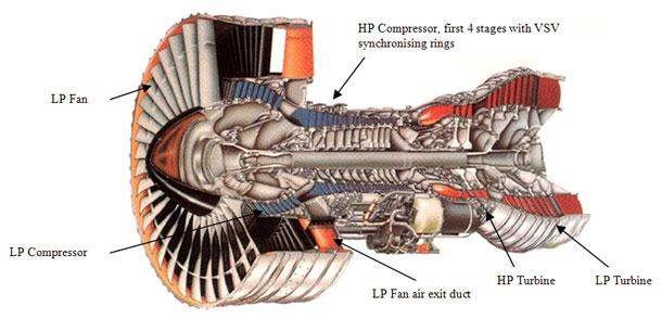
The Pratt & Whitney PW4000 is a third generation, high bypass ratio, commercial turbofan engine (see Figure 1). PW4000 engines have two spools with separate primary and fan duct exhaust systems. The engine has a compression ratio of approximately 30 to 1 and a fan-air to primary-air bypass ratio of approximately 5 to 1.
The low pressure spool (N1) consists of a single stage fan, four-stage low pressure compressor (LPC) and a four-stage low pressure turbine (LPT) on a common shaft.
The high pressure spool (N2) consists of eleven compressor stages driven by a two-stage turbine. The first four stages of the high pressure compressor (HPC) incorporate variable stator vanes (VSV), which are positioned automatically by the full authority digital electronic control.
It utilizes VSV and bleed valves to maintain acceptable stall3 margins throughout the operating envelope of the engine. The VSV are commanded via unison rings and vane arms to change their angle of attack and therefore the angle of attack of the inlet air relative to the compressor blades of the compressor stages at varying engine thrust settings.
Figure 1: PW4000 engine.4
The engines also employ Active Clearance Control, which controls the clearances between the turbine blade tips and the turbine case to improve operating efficiency in cruise flight.
Engine disassembly and inspection
Pratt & Whitney engine model PW4056, serial number P724374 was received into the heavy maintenance contractor facility under the supervision of the Aviation Safety Council of Taiwan. The low pressure fan was examined for bird strike damage, with no evidence of such an event found. Upon disassembly, extensive mechanical and thermal damage was noted throughout the engine downstream of the 6th stage compressor. This included severe debris induced airfoil damage to the high pressure compressor (HPC) stages 6 through 15. All 5th stage blades exhibited evidence of blade rubbing at the trailing edge tips, as well as numerous minor debris impact dents to the airfoil trailing edge. The 5th stage VSV also displayed evidence of debris damage to the trailing edges of some vanes. The 5th stage circumferential rub strip had minor abrasion damage; however the 6th and 7th stage rub strips were heavily damaged and were beyond repair limits. The HPC drum also displayed evidence of scraping damage to the knife-edge seals at the 10th and 11th stages.
A boroscope inspection (BSI) was then carried out to inspect the engine gas path. That inspection revealed coating loss and metal spray on the T1 (first stage) nozzle guide vane (NGV). Molten metal was also found blocking several BSI ports.
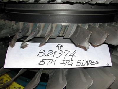
Associated with this was severe impact damage and molten metal spatter to the stator sections of the HPC, particularly the 5th through 14th rotor stages. With the HPC stator and case halves removed, the entire HPC blade rows were examined from front to rear. One HPC blade at the 6th stage was found to be fractured (see Figure 2). The blade attachment for this blade was observed to be intact and still retained within its dove tail slot in the disc. The broken blade attachment was removed and forwarded to a metallurgical laboratory for further analysis.
Figure 2: 6th stage HPC blade missing.
Further examination of the HPC turbine found burning and erosion of the leading-edge tips and also tip rubbing on the T1 turbine blades, and impact damage from debris to the T2 (second stage) NGV with cracking to the concave face of the airfoil. Molten metal spray was also evident between the diffuser case and outer combustion chamber.
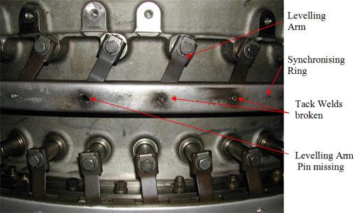
Of note during the engine inspection was the absence of arm attachment pins at the 10 o'clock and 12 o'clock positions for the (VSV) vane arms in the 6th compressor stage synchronizing ring. The remnants of tack-weld material were observed on the synchronizing ring at both locations where the pins were missing.
A pronounced looseness of the remaining four arm attachment pins between these two clock positions on the ring (see Figure 3) was also observed.
Figure 3: VSV synchronising ring and vane arms.
A levelling pin flare diameter check was carried out on the VSV ring assembly during the engine inspection and the measurements recorded for the investigation. It was found, with the exception of one pin, that all pin flare diameters were below the acceptable minimum limit stipulated in the engine manufacturer's table of limits. This flare diameter measurement check, also stipulated in the engine manufacturer's manual5, was to be accomplished prior to the tack welding of the pins to the unison ring. The overhaul facility informed the ATSB that there was no stipulation by the manufacturer to check pin flare diameter after the tack weld process had been completed.
Metallurgical examination of failed blade
The blade platform was examined using macro observation, photographic, fractographic and chemical composition techniques6.
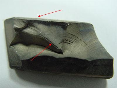
There was evidence of galling to the attachment element faying surfaces of the blade platform. The surfaces were coated with an anti-galling compound during assembly and this compound appeared to have been degraded during the engine's service life. The blade exhibited two crack origin points; one on the pressure side of the airfoil section measuring 3 mm in height from the platform and the other on the opposite surface measuring 2 mm in height from the platform (see Figure 4).
The fracture sites also exhibited distinct beach marking and were typical of a fatigue type crack propagated under high cyclic stress. The striations present indicated that the cracks, which initiated from either side of the airfoil, were as a result of high alternating vibratory stress.
Figure 4: Crack origins (two places).
Engine history
The engine P724374 had completed 14,914 hours and 3,320 cycles since last overhaul at an approved facility in Singapore. During that shop visit, the VSV synchronizing ring vane arm pins were re-flared after pin replacement. The PW4000 engine family had a history of the pins working loose and allowing vanes to cause turbulent engine airflow when liberated from the synchronizing ring, which drove them. This turbulence was a result of the stator vane being allowed to move away from the scheduled vane angle commanded by the engine EEC. There were also instances recorded by the engine manufacturer of this off-schedule movement resulting in HPC compressor blade stress and in several instances, actual failure of the blade in an identical fashion to the failure observed in this investigation.
The engine manufacturer had published several service bulletins (SBs) requiring repetitive inspections in the interim until a more permanent solution could be applied. These SBs required the synchronizing ring rivet pins to be inspected at regular intervals. During the SB accomplishment process on the occurrence engine, all 23 vane arm pins were removed and replaced with new items.
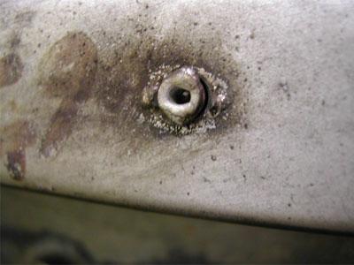
Pratt & Whitney Service Bulletin PW4ENG 72-432 R3 then called up a tack weld of the pins to secure them in place on the synchronizing ring. This process was re-certified as completed on the occurrence engine after the pin replacement and completion of the flaring. The overhaul facility stated that the pin flaring was accomplished in accordance with the manufacturer's required tolerances. Compliance with this weld process was believed by the manufacturer to remedy the problem of pin wear and looseness, and be terminating action on the repetitive inspection requirements. However, the pins were lost even though they had undergone this tack weld process after their replacement (see Figure 5).
Figure 5: Broken tack weld remnants on synchronising ring.
1 Type Certificate Data Sheet E24NE specifies a maximum continuous limit of 629o C. The FIM specifies the maximum operating temperature as 650 deg C. At 662 deg C, the temperature was 12 deg C above the maximum operating temperature for a period of 22 seconds. The temperature may have been greater due to EGT Probe blockage and Turbine Cooling Air restriction by molten titanium from the HPC meltdown.
2 MAYDAY is the international broadcast for urgent assistance.
3 Stall occurs in a turbine engine when the airflow around the compressor blades degenerates and becomes turbulent, destroying the smooth flow of air through the compressor. It may affect one stage or a group of stages.
4 Cutaway source: Pratt & Whitney.
5 Pratt & Whitney PW4000 (94"/100") CIR manual (PN 51A357).
6 Chung Shan Institute of Science and Technology, Aeronautical Systems Research Division, Aero Materials Section, Taiwan R.O.C Report Number 930107.


