
History of the flight
Shortly after take-off from runway 34L at Sydney, the flight crew of the Boeing 747-400 aircraft received a forward cargo compartment fire warning on the Engine Indicating and Crew Alerting System (EICAS). On receiving the warning message the crew actioned the appropriate checklist, activated the fire suppression system and transmitted a MAYDAY. At the same time, flight attendants noticed a fine mist and the smell of smoke in the passenger cabin. The crew then returned the aircraft to Sydney, where an uneventful overweight landing was conducted.
Prior to landing, the EICAS fire warning message ceased. This indicated that the aircraft fire suppression system may have successfully extinguished any fire, however the cabin fumes were still evident. After landing, the flight crew stopped the aircraft on the runway where emergency services came to their assistance. After confirming with the flight crew that the fire warning message was no longer present, the emergency services assessed the aircraft from the ground, then allowed the passengers and cabin crew to disembark to a safe distance via mobile stairs positioned at the aircraft's front left door. Once the passengers and cabin crew were clear of the aircraft, the emergency services opened the forward cargo door.
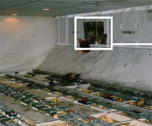
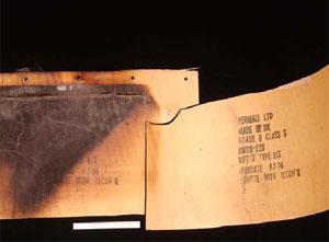
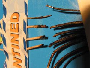
A hot spot was detected on the left side of the forward cargo bay at body station STA900, where the side wall lining was found to be heat affected. Removal of the lining revealed burned insulation blanket material, discolouration of the aircraft skin and burned/broken electrical wires that powered the forward galley chiller boost fan situated in the area (see Fig 1). As the fire was no longer evident, ground engineers isolated the chiller boost fan electrical circuit and towed the aircraft clear of the runway.
|
|
| FIGURE 1: Forward cargo bay with expanded view of chiller boost fan location | |
Aircraft structural damage
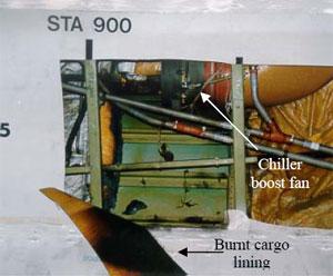
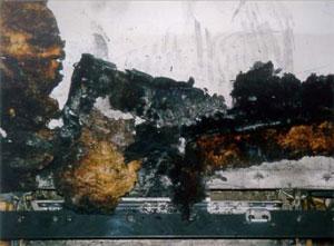
Non-destructive testing to check for cracking and conductivity of the aircraft skin adjacent to the affected area was carried out. No cracks were detected, however the conductivity test revealed three locations where the skin had been substantially affected by heat (see Fig 2). The most severely affected area required a temporary skin repair before the aircraft could be flown back to the operator's maintenance facility in the United Kingdom, where the heat-affected aircraft skin was replaced.
|
|
| FIGURE 2: Heat affected areas | |
Sidewall lining and insulation blankets
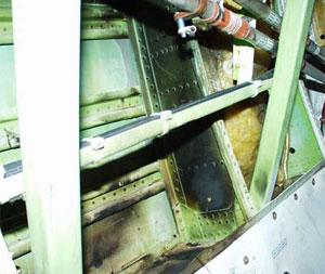
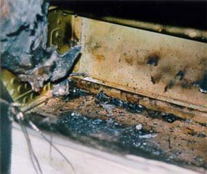
The fibreglass sidewall lining between STA880 to STA900 was visibly heat damaged with discolouration observed on the side facing into the cargo compartment. Inspection of the reverse side revealed burned layers of fibreglass confined to a localised area approximately 30cm x 45cm (see Fig. 3). The insulation blankets that lined the aircraft skin were made of a fibreglass core with a metallised TedlarTM film on one side and a MylarTM film on the other and had been subjected to localised heat and fire (see Fig. 4).
Samples of the sidewall lining and insulation blanket were sent to the United States of America, Federal Aviation Administration (FAA) technical centre and the aircraft manufacturer for analysis and testing.
|
|
| FIGURE 3: Sidewall lining | FIGURE 4: Insulation blanket |
The examinations determined that both the sidewall lining and insulation blanket samples complied with the appropriate material specifications for aircraft use.
The flammability testing, conducted by the FAA, on samples of the insulation blanket included a vertical Bunsen burner test, which was mandated in Federal Aviation Regulation FAR 25.853 - Appendix F. The samples tested met the requirements, but due to their limited size, the result was not conclusive as to the integrity of the entire blanket.
The aircraft manufacturer's tests revealed contamination on the insulation blanket samples. This contamination consisted of environmental dust, fibres and corrosion inhibiting compound. These contaminants were consistent with general contamination found during evaluations of other in-service insulation blankets and were considered to be normal.
The aircraft manufacturer's 'flame propagation cotton swab tests' found areas on the blanket samples that were self-extinguishing while other areas showed "flame propagation uncharacteristic of that expected for new insulation blankets". It was unknown whether contamination, in-service ageing, or heat exposure, or a combination of these, altered the blanket's flame propagation characteristics.
Boost fan system
A galley chiller boost fan system was installed in the aircraft to provide forced air circulation over the forward galley chiller units increasing their cooling efficiency. The system incorporated a vaneaxial-type three-phase fan, powered by the aircraft's number 3 alternating current electrical system. Control power was supplied by the aircraft's direct current electrical system, with operation being automatic on selection of the galley chillers to ON. Circuit protection was provided by a 20 ampere circuit breaker and a cargo fire cutoff relay.
Chiller boost fan
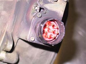
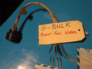
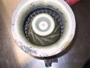
An inspection of the boost fan revealed a burn hole and sooting on its casing adjacent to the electrical terminal (see Fig. 5). The electrical wiring to the fan was found to have four of its seven wires broken, with all of the wires displaying sooting discolouration (see Fig's. 6 and 7). The soot marks corresponded to those on the fan casing and when positioned together, revealed that the wires had separated at a point adjacent to the corner of the electrical terminal. The failure of the wires produced electrical arcing, which melted the casing, resulting in the burn hole observed.
Further inspection found that all of the fan impeller blades had failed just above their roots (see Fig. 8). Neither the impeller nor the fan shroud showed signs of hard body impact damage.
|
|
| FIGURE 5: Electrical terminal | FIGURE 6: Broken wires |
|
|
| FIGURE 7: Sooting evident | FIGURE 8: Fan impeller blades failed |
Technical examination of the fan found that the impeller was made from a moulded resin material. There was no evidence of any pre-existing defects or cracking found on the blade fracture surfaces. However, a number of blades showed breakage of a curved lip of material from their forward corner. This condition was consistent with overload fatigue possibly due to the blade tips contacting the fan shroud. Such a condition may have occurred prior to the blades total failure. The inside surface of the impeller was coated with a brown powder, determined to be primarily iron oxide.
The aluminium alloy shroud contained several circumferential wear marks that were adjacent to the impeller blade path. Although there were random scratches, no evidence of gouging or penetration of the shroud skin was found.
Further disassembly of the fan revealed wear on the electrical motor stator, indicating that it had been subjected to armature rubbing. The armature did not display similar wear patterns. Rubbing of this nature usually occurs as a result of bearing failure or excessive wear, leading to armature oscillations. For the full technical report see Attachment 'A'
Chiller boost fan service history
The chiller boost fan entered service in 1994, with the last overhaul being in June 2000, after removal from service because of electrical failure. The maintenance records for that overhaul stated: "Unit noisy due worn bearings, all other parameters ok. Reported defect not confirmed. Disassembled, cleaned and inspected, bearings renewed, unit reassembled and tested to spec". The fan was then fitted to the incident aircraft on 2 August 2000. No subsequent maintenance was recorded.
Chiller boost fan circuit breaker and electrical relay
The installed circuit breaker was a 20 ampere three-phase, push-pull high performance, trip free type, designed for aircraft installations. It's design allowed for increased amperage through the circuit for a specific time before tripping (breaking the circuit) and was used in large motor load applications where the inrush current would trip a standard circuit breaker. The length of time taken to cause the circuit breaker to trip varied according to the current it received. The aircraft manufacturer advised that "At 385 per cent or 400 per cent [load rating], this breaker will trip between 2.3 to 10 seconds". This prevented aircraft electrical power surges from "nuisance" tripping of the circuit breaker and rendering the boost fan inoperative.
A number of tests were conducted on the circuit breaker, including a 'load withstanding test'. This required the controlled increase in current through the circuit breaker, with time to trip recorded. This test was conducted at 105 per cent, 140 per cent and 200 per cent values, as per the manufacturers test procedures.
The installed relay was a 25 ampere, electromagnetic, three pole, single throw, normally open type. This was also subjected to a number of tests including 'Coil resistance', 'Coil hold and drop voltage' and 'Voltage drop and switching test across all three phases'.
These tests were performed under the supervision of the United Kingdom Air Accident Investigation Branch. Both components were found to comply with their operational specifications, with no adverse mechanical or operational functions found during the testing. As a result, both components were considered to be serviceable.
Quick Access Recorder
The aircraft's Quick Access Recorder (QAR) data was analysed by the Australian Transport Safety Bureau with the following information retrieved.
During climb the number 3 alternating current system showed a momentary increase in load from a nominal 31 per cent to 54 per cent, which equated to an increase in current draw of 57 amperes.
Four seconds later, the load was again recorded and had returned to the nominal 30 percentage range, where it remained for the rest of the flight.
Approximately 1 minute later the QAR recorded a forward cargo fire.
Approximately 3 minutes later, the first cargo fire bottle low quantity message appeared, indicating that extinguishant had been discharged successfully.
Other recorded data received from the aircraft's central maintenance computer (CMC) confirmed the arming of the fire bottles approximately 2 minutes after the fire warning and the discharging of the last two fire bottles after the aircraft landed.
Cargo fire detection/extinguishing system
The aircraft incorporated two dual loop smoke detectors in each cargo compartment. Air from throughout the compartment was drawn through the detectors and sampled. In normal operation, both loops must sense smoke for a fire warning to be activated. If the system detects a loop fault during self-test at aircraft power on, it would reconfigure to a single loop operation.
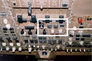
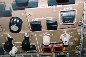
The cargo fire module located on the overhead instrument panel in the flight deck incorporated forward and aft compartment ARM buttons and a DISCH discharge button. On sensing smoke, the relevant ARM button, along with an EICAS message would be illuminated, alerting the crew of the fire. The crew must then push the ARM button in. This action disables electrical power to a number of circuits, including the galley chiller fan circuit. Extinguishing is then achieved by pressing the DISCH button (see Fig. 9).
|
|
| FIGURE 9: Overhead instrument panel with expanded view of cargo fire panel | |
Four fire extinguisher bottles (A, B, C and D) service the cargo compartments, each having discharge lines to both the forward or aft compartments. On depression of the DISCH switch, bottles A and B discharge flooding the selected compartment with extinguishing agent. Bottles C and D are not discharged until 30 minutes later. If the aircraft reaches the ground before the 30 minutes are up, the bottles will discharge on touch down. The system was designed to give up to 180 minutes of discharge time.