
After landing, and while taxying to the terminal, the co-pilot of the Beechcraft 1900D aircraft turned the landing lights off. He then contacted Air Traffic Control, cancelling SARWATCH. During this radio transmission, the MASTER WARNING and right AC bus (R AC BUS) warning captions illuminated, closely followed by illumination of the right fuel low pressure (R FUEL PRESS LOW) warning.
The crew immediately carried out the company check list actions for the right AC bus failure, but decided not to implement the actions for the right fuel low pressure warning as the aircraft was close to the terminal. The checklist actions for the right low fuel pressure indication required the standby boost pump to be switched on. The co-pilot then detected an acrid smell in the cockpit and alerted the pilot to flames he had observed coming from the underside of the right engine nacelle. The pilot in command immediately brought the aircraft to a stop, shutting down both engines.
Although there was no engine fire warning indication, the crew operated both engine fire handles, making several unsuccessful attempts to discharge the right engine fire bottle. The co-pilot then evacuated the passengers through the forward cabin door, directing them to the flood lit terminal apron area. The pilot in command alerted the RAAF fire personnel by radio of the fire, before turning off the aircraft power and vacating the aircraft.
Two of the operator's maintenance engineers, awaiting the aircraft's arrival, had noticed the flames emanating from the wheel well area as the aircraft approached. They had immediately picked up two dry chemical powder fire extinguishers and approached the aircraft. Following the feathering of the right propeller, they discharged the contents of both fire extinguishers into the right main landing gear wheel well area, extinguishing the fire. The military fire tender arrived soon after to assist.
Investigation
The investigation found that there had been a fuel-fed fire in the area to the rear of the right main landing gear wheel well, and in the right wing equipment bay area positioned immediately outboard of the right engine nacelle. The fire had severely damaged the airframe structure, wiring and components in both areas. The greatest damage was evident in the rear of the wheel well. The aluminium inner fender panel assembly, positioned at the rear of the right wheel well, had partially melted during the fire, leaving a trail of molten aluminium that extended back along the taxiway.
Fuel to the fire had been supplied from two damaged aluminium alloy fuel tank lines in the right wing equipment bay. One line was positioned toward the front of the enclosed equipment bay area, and the other toward the rear. Examination of the surfaces of both fuel lines indicated that they had been in contact with powered electrical wiring. This contact had resulted in electrical arcing, with holes being burnt completely through the walls of both fuel lines. The wiring supplied power to the right, wing mounted, 450 watt landing light.
The damaged fuel line, positioned in the forward area of the bay, was the fuel transfer motive flow line that supplied the operating pressure to the forward fuel transfer jet pump (See Fig 1). The jet pump transferred the fuel from the main wing tanks to the wing mounted collector tank, ensuring a constant fuel supply for the engine driven pump. This line was pressurised with fuel from the engine driven fuel pump, or by the electric standby boost pump when that pump was turned on.
The damaged fuel line in the rear of the bay was part of the main fuel supply from the wing mounted collector tank to the engine driven pump. The line was positioned between the fuel filter shut-off valve, just forward of the wing main spar and the fuel filter assembly.
The standby electric pump, located in the bottom of the collector tank, served as a backup to the engine driven pump in the event of a failure of that pump, and could be manually selected on by the flight crew. The pump also activated automatically during a normal engine start sequence.
Low fuel pressure from either the engine driven pump or the standby pump was indicated by the illumination of the left or right fuel pressure low (L or R FUEL PRESS LOW) warning annunciator.
The fuel leak in the engine driven pump supply line was stopped by maintenance personnel soon after the incident, by manually closing the fuel shut-off valve positioned on the front of the fuel collector tank. There was no mechanical method of isolating the leak from the motive flow line. The fuel flow from this line was temporarily stemmed by the fitting of a rubberised electrical wiring loom clamp over the hole in the line.
The electrically activated right engine firewall shut-off valve was found to be in the open position.
Electrical
The landing light system operating voltage was 28 volts DC. The 450 watt landing light receives its power from the K11 relay, positioned in the rear of the right engine nacelle area. The relay contactor switching wiring was protected by a 10 amp circuit breaker positioned in the aircraft underfloor area. The electrical wiring leading to and from the K11 relay to power the landing light, was protected from a prolonged overcurrent situation by a 35 amp mechanical indicating, enclosed link, current limiting fuse. This device was utilised to allow a transient high current draw that would occur during the landing light initial illumination. Examination of the fuse revealed that the mechanical indicating pin had triggered. This indicated that the internal fusible link had melted.
The landing lights were normally switched on during descent at the transition altitude of 10,000 ft. This was done as a part of the operator's transition checklist actions. In this instance, the crew advised that the lights were turned as the aircraft descended through 11,300 ft. No abnormal operation of the lights was noticed at any time, with good illumination of the runway for landing.
The electrical wiring was examined and found to be of the correct specification as detailed by the manufacturer. The wiring had a copper core with the insulation surrounding the wire manufactured from white extruded ethylene-tetrafluoroethylene copolymer (ETFE). The surface of the wiring and aluminium fuel line tubing was microscopically examined, with no evidence found of any rubbing on or around the arcing points.
The aircraft manufacturer indicated that the normal method for the positioning and securing of the electric wiring, in areas such as the right-wing equipment bay, was by utilising plastic cable ties (See Fig 3). The ties would be routed through lengths of plastic tubing that acted as cable stand-offs. These were to used to securely position the electrical wiring, and ensure that it did not come into contact with the adjacent fuel lines.
An inspection of other Beechcraft 1900 aircraft in the operator's fleet revealed cable tie and tubing stand-offs securing the landing light wires. These were attached around the fire sleeving on the wing de-ice boot pneumatic lines in the forward area of the bay.
The inspection of the area around the motive flow fuel line on the accident aircraft, revealed that one of the two landing light wires was in contact with the surface of the fuel line. No plastic stand-offs were fitted to space the landing light wiring away from the fuel line. There was however, evidence of a soot-covered imprint of a plastic cable tie on the surface of the fire sleeving (See Fig 4). This fire sleeving surrounded the adjacent wing de-ice boot pneumatic line.
The remains of another plastic stand-off, on the nearby positioned standby fuel pump power wiring, was still evident (See Fig 5).
The aircraft had been subjected to severe hail damage in 1995. During the repairs following this damage, the right-wing leading edge de-ice boots were removed and the pneumatic de-ice lines were disturbed.
The landing light wiring, positioned above the damaged main fuel supply line, was manufactured longer than required. This excess wiring had then been doubled back on itself and tied, with a cable tie, along the main wiring loom into this area. This wiring had also been in contact with the fuel line.
When examined the contacts on the K11 landing light relay exhibited signs of arcing due to excessive 'contact bounce'. 'Contact bounce' is an oscillation of the relay contacts. This condition can be exaggerated as a result of the effects of heat and in-service wear on the springs and latches that control and damp the relay contact movement. With excessive 'contact bounce' present, it is possible for the wiring served by the relay to heat up due to a continually higher than normal current flowing through the wiring. Following removal of the landing light wiring insulation by the ATSB, there was evidence seen of excessive heat on the wiring surface. Plastic deformation of the wiring's ETFE insulation was noted at the point of arcing on the fuel line positioned at the front of the bay.
Fire
The fire damage was most severe in the rear of the wheel well area, this was evidenced by the melted aluminium alloy panel, the distorted wheel well surrounding structure and some destroyed ETFE wiring insulation.
The fuel, from the leaking equipment bay lines, had flowed along the face of the wing spar towards the wheel well area as the amount of fuel increased. The fuel was then able to flow onto the top of the right main gear up position indicator switch, through a hole in the inner fender assembly panel immediately above. The wheel well area was open to the airflow and to the propeller wash at the rear lower end of the inner fender panel.
Air was also drawn from behind the fender panel by the inverter cooling fan positioned in the rear of the engine nacelle area. This cooling air flowed from the wheel well through the rear of the equipment bay, and was ducted along under the right side of the engine nacelle cowling. The duct exhibited signs of heavy sooting and some of the inverter cooling fan plastic blade tips had melted.
The area at the rear of the right-wing equipment bay, through which the inverter cooling air was drawn, was the most heat-affected area of the bay. Some of the ETFE wiring insulation in this area was completely burnt away. The forward end of the bay, in the area of the other fuel leak, exhibited some wiring damage and medium to heavy sooting. In this area there was also evidence of 'washing' of fuel against the upper access panel (See Fig 6). The wiring and components that were immediately adjacent to the fuel leak in the area were not as heat affected as in other parts of the zone.
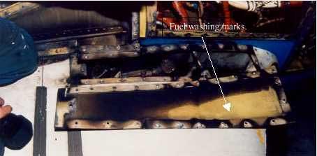
View of upper surface of right wing, showing fuel 'washing' on upper access panel
A typical hydrocarbon fuelled ground fire would burn at a temperature in the range of 870 0 C to 1093 oC. An inflight fire, with the added oxygen, would burn in excess of 1093 oC, often up to 1371 oC and higher. The aluminium alloy in aircraft becomes plastic at 454 o C and melts at about 677 oC, while the extruded ETFE insulation on the electrical wiring, melts at approximately 300 o C. The cable ties are made from either Teflon or nylon and have a similar melting point of 280 o C to 300 oC
Engine isolation and fire extinguishing system The aircraft was equipped with an engine isolation and fire extinguishing system that was activated by the operation of a fire emergency tee handle. The operation of the fire handle cuts fuel to the selected engine and arms the engine fire extinguisher bottle. The pilot can then discharge the fire extinguisher by depressing an instrument panel mounted switch.
During the shutdown of the aircraft prior to passenger evacuation, the flight crew had activated the engine fire handles and attempted to discharge the right engine fire bottle several times. The fire bottle, however, had not discharged and the fire wall fuel shut-off valve had not closed. An inspection of these emergency systems revealed that the components had not operated because of fire damage that had occurred to the electrical wiring to these components. The right side firewall shut-off valve circuit breaker was found to have tripped during the incident. Regardless, the operation of the system would not have had any effect in this instance, due to the fire being in an area outside the engine fire zone.
Following an inspection of the manufacturer's maintenance procedures for the aircraft type, it was discovered that there was no procedure for determining the serviceability of the fire bottle activation system that ensured there was sufficient voltage at the fire bottle electrical connection to activate the bottle. This has been brought to the attention of the aircraft manufacturer.