Boeing Commercial Aircraft Group, 747-436, G-BNLK
1. FACTUAL INFORMATION
1.1. Examination brief
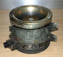
The disassembled components of an electric air-cooling fan
(figure 1) were received by the ATSB Technical Analysis unit for
examination and analysis of the damaged fan impeller. The fan unit
had been fitted to a Boeing 747 aircraft (registration G-BNLK) to
provide forced air circulation for a forward galley chiller unit.
During the early stages of a flight on 10 August 2002, a small fire
developed in the forward cargo compartment adjacent to this unit
(figure 2). Physical and recorded evidence suggested the fire had
initiated from electrical arcing that was a result of a wiring
short-circuit near the fan terminal housing.
 |
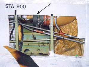 |
| FIGURE 1: Cooling fan assembly. Inlet is at top. | FIGURE 2: Cooling fan location (arrowed) behind cargo hold wall. |
1.2. Samples received
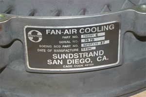
Data plates affixed to the fan housing (figures 3 & 4)
identified the unit as a three-phase unit (part number 73259E,
serial number 3676), manufactured by Sunstrand (San Diego,
California) in 1994. The fan was an axial flow design, with a
single bell-shaped impeller manufactured from a moulded resin
material. The motor and fan outlet guide vane assembly shared an
integral housing which also carried the (damaged) electrical
terminal housing. The motor was a brushless (induction) design,
with the armature supported on sealed rolling element bearings.
Surrounding the impeller was an aluminium shroud, which formed the
fan intake and also provided for the mounting and support of the
unit and its associated ducting.
 |
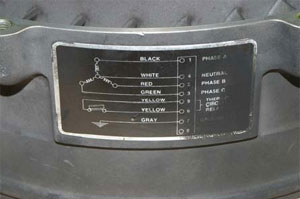 |
| FIGURE 3 & 4: Data and wiring information plates affixed to the fan housing. |
|
1.3. Visual examination
1.3.1. Impeller
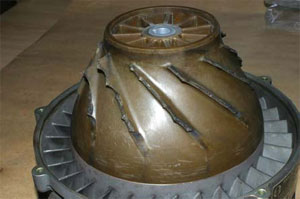
The impeller unit had been effectively 'cobbed', with all eleven
blades fractured at or immediately adjacent to the impeller hub
(figure 5). The uneven, irregular nature of the fractures suggested
the failure occurred as a cascading fragmentation event, with
multiple sections of blade breaking away and striking others,
causing further break-up. A study of all fracture surfaces failed
to identify any evidence of pre-existing defects or cracking that
may have precipitated the initial blade failure, nor was any
indication found of unusual hard-object impact damage that may have
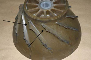
suggested foreign object ingestion. There was some evidence however
that suggested early damage to the impeller blade forward corners -
many blades showed breakage of a curved lip of material from the
corners in a manner that suggested possible contact with the fan
shroud (figure 6).
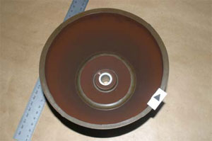
The inside surfaces of the impeller body carried a heavy coating
of a powdery brown dust (figure 7), which was also evident inside
the armature core and around the end of the motor housing. This
material was loose and easily wiped away by hand and a sample was
taken for later qualitative chemical analysis.
 |
 |
| FIGURE 5: 'Cobbing' of all the blades from the impeller body. |
FIGURE 6: Scalloped fracture form at the forward edge of several impeller blades. |
 |
|
| FIGURE 7: Dusty brown deposit on inside of impeller body. |
|
1.3.2. Fan shroud
Produced as a machined die-casting from an aluminium alloy, the
fan shroud encased the full impeller length and showed no evidence
of having failed to fully contain the fractured impeller blades.
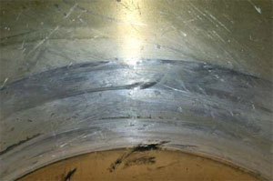
Around the blade tip path, the shroud internal surfaces showed
several circumferential wear bands that indicated significant tip
interference (figure 8). These were most clearly defined at the
forward and rear limits of the blade path. Random indentation and
scratching damage was noted around the shroud 'throat' region -
this was consistent with the effect of multiple fragment impacts
produced by the failing impeller blades. No specific evidence of
hard-object impact damage was found across the blade path. Dark,
waxy stains produced by an unidentified liquid draining through the
fan shroud were noted at the low-point of the assembly (figure 9)
and a series of tide-marks were formed on the front face of the
shroud as the liquid had accumulated and later drained away.
 |
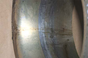 |
| FIGURE 8: Fan shroud showing prominent evidence of rotational contact. |
FIGURE 9: Fan shroud with stains from liquid draining through the assembly. |
1.3.3. Fan motor and housing
Being a brushless three-phase induction motor, the unit was
comparatively simple in construction, with a star-wound stator
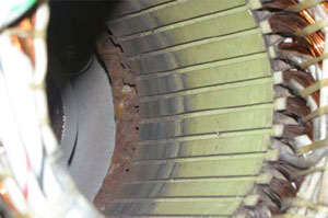
containing a compact cage-type armature. Internal inspection found
evidence of rub and erosion of the iron stator former over the
innermost twenty millimetres of the stator length (figure 10),
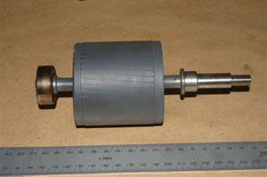
however the armature did not reflect this and showed no evidence of
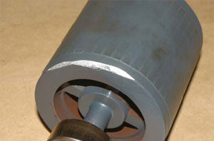
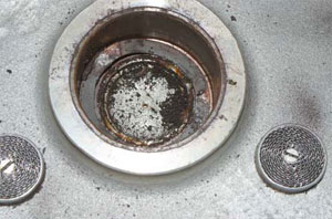
operational damage (figure 11). Several areas where material had
been removed by bevelling the core corners were evidence that the
armature had been re-balanced at some time following original
manufacture (figure 12). Both armature shaft bearings rotated
smoothly by hand and showed no notable indications of distress or
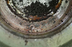
abnormal operation. The rear armature bearing housing (figure 13)
contained particulate debris that appeared to be the fine brown
dust mixed with lubricant lost from the bearing unit. The contact
points of the leaf spring and the housing bottom showed light
fretting damage (figure 14), with some evidence of rotation also
noted.
 |
 |
| FIGURE 10: Motor stator inside surface showing clear evidence of rotational contact against the armature. |
FIGURE 11: Motor armature showing no evidence of contact with the stator. |
 |
 |
| FIGURE 12: Motor armature with material removed for balancing purposes. |
FIGURE 13: Motor end bearing housing with contaminants found. |
 |
 |
| FIGURE 14: Area of fretting damage found between the seating spring and housing base. |
FIGURE 15: Electrical arcing damage and associated metal loss. |
The fan motor electrical supply was routed behind the outlet
guide vanes and terminated in an external housing fitted with an
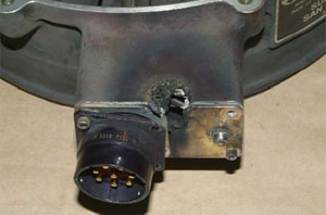
eight-pole connector. A localised area of heavy electrical arcing
was clearly evident adjacent to the connector and had resulted in
the melting and loss of around ten to fifteen millimetres of
material in a v-shaped notch from both the front and side faces of
the connector housing (figure 15). The metal loss had exposed some
of the internal wiring and had produced an appreciable level of
heating around the contact area, as evident from the tinting of the
surrounding surfaces.
1.4. Dust analysis
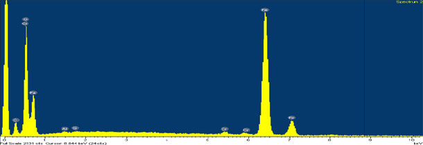
The sample of brown dust recovered from the underside of the
impeller body was qualitatively analysed using energy-dispersive
x-ray spectroscopy techniques under the scanning electron
microscope. The results of this testwork (figure 16) showed the
material to be comprised primarily of an iron-oxide compound, with
traces of chromium, aluminium and silicon.
 |
| FIGURE 16: EDS spectra for the brown dust found beneath the impeller. Strong Fe and O peaks. |
2. ANALYSIS
2.1. Impeller failure
All of the failed impeller blades exhibited brittle overload
fractures. No evidence of material flaws, cracks or other
pre-existing damage was shown by the blade stubs, however this was
not conclusive, given the opportunity was not available to examine
all of the blade remnants. Resin materials such as that used to
manufacture the impeller have an inherent lack of ductility and as
such, are prone to cracking and fracture under impact or elevated
stress conditions. While no direct evidence was found to suggest
the ingestion of foreign object/s, the damage sustained was not
unlike that expected from such an event, and thus this possibility
cannot be discounted.
2.2. Motor damage
The abrasion exhibited by the inner sections of the stator
assembly was believed to be evidence of armature contact,
presumably caused by the failure and collapse of the end bearing
unit. The dust under the fan impeller was believed to be an
accumulation of wear products from this contact - both the stator
former and the armature core were ferrous alloys, while the
remainder of the motor and fan assembly was predominantly aluminium
based materials. Given that the installed armature showed no
indication of stator contact and the end bearing was sound, it was
concluded that the stator damage was a product of a previous
failure that had been repaired by replacement of the armature and
the re-use of the remaining components, including the impeller.
The collapse and failure of an armature shaft bearing and the
shaft misalignment that results would be expected to alter the
impeller - shroud clearances, with a risk of contact between the
shroud and the impeller blade tips if the misalignment became
severe enough. Impeller blade tip contact, if it did not produce
immediate blade breakage, may produce latent cracking damage that
could lead to later blade failures if not detected. While there was
no evidence found to suggest that pre-existing damage of this
nature existed, the possibility remained that this damage had been
sustained given the evidence of the rear bearing failure and the
contact marks inside the fan shroud.
2.3. Vibration
Rotary equipment such as the cooling fan relies upon accurate
dynamic balancing to minimise the vibration induced during
operation. Events such as the impeller failure will disrupt the
balance of the assembly and can lead to significantly increased
vibration levels. Wiring or piping that is installed against or in
contact with the vibrating equipment may sustain fretting or
erosion damage if the external protection or insulation has not
safeguarded against this event.
3. CONCLUSIONS
3.1. Findings
- The cooling fan impeller had sustained gross breakage of all
blades at or adjacent to the body of the impeller. - All fractures were brittle in nature and showed no evidence of
pre-existing defects. - No evidence of foreign object damage was found.
- The fracture profiles of some blades suggested preferential tip
breakage before the complete blade failure. - The fan motor showed evidence of a previous rear bearing
failure that had produced contact and wear between the armature and
the stator. The armature had subsequently been replaced, however
the stator and other motor components remained in service. - The previous bearing failure may have allowed operating contact
between the impeller blade tips and the fan shroud. This contact
may have produced blade cracking which predisposed the impeller to
failure in the manner observed. - After failure, the fan impeller would have presented a
significant unbalanced load to the fan.


