Sikorsky S76 Helicopter, VH-EXX
1. FACTUAL INFORMATION
1.1 Introduction
A Sikorsky S76C helicopter (VH-EXX) sustained a failure of the
number-two engine during cruise flight. The failed engine was a
Turbomeca Arriel 1S1 turboshaft engine, serial number 15038 and had
accumulated 7,935 hours and 6,784 cycles since new.
Reports from the flight crew indicated that the engine failure
was associated with a loss of gas-generator turbine speed and an
escalation of turbine outlet temperatures. Fire warnings for the
engine were also received, prompting the pilot commanded shutdown
of the engine and discharging of the fire suppression system.
1.2 Engine examination
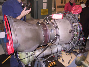
Disassembly of the engine (figure 1) was carried out at the
Bankstown (NSW) facility of Turbomeca Pty Ltd, in the presence of
representatives from the engine manufacturer, the helicopter
operator and the Australian Transport Safety Bureau. The
examination revealed the following significant damage to the
operating components of the engine:
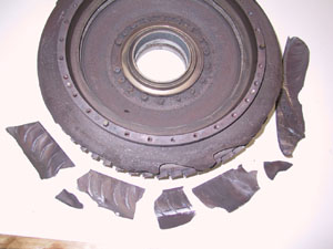
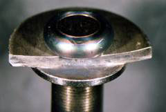
- Outer wall of the centrifugal diffuser cracked and separated
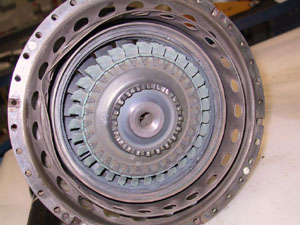
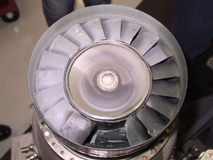
into seven pieces over half the circumference (figure 2). - First-stage gas-generator turbine blades oxidised and burnt
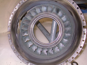
over the outermost third of their length (figure 3). - Second-stage nozzle guide vanes extensively overheated and
partially melted on the convex (trailing) face and on the trailing
edges (figure 4). - Second-stage gas-generator turbine blade number 16 fractured
beneath the platform. Remaining blades burnt and mechanically
damaged on tip edges (figure 5). - Second-stage NGV housing indented and punctured,
circumferential cracking extending from this area (figure 6). - Power turbine NGV missing two vanes; the remainder showing
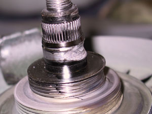
mechanical damage (figure 7). - Number-three (rear) bearing collapsed, showing extensive
overheating and out-of-balance damage to races and adjacent seals
(figure 8). - Rear bearing air vent and oil return lines fractured from
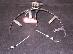
outside of housing (figure 9). - Two of the three T5 thermocouples burnt away completely (figure
10).
|
Figure 1. Arrial 1S1 engine, serial number |
Figure 2. Diffuser assembly, showing break-up |
|
Figure 3. First-stage gas-generator turbine |
Figure 4. Second-stage nozzle guide vanes |
|
Figure 5. Second-stage gas-generator turbine |
Figure 4. Second-stage NGV housing with a large |
|
Figure 7. Power turbine NGV assembly, missing a |
Figure 8. Rear bearing race and rotating air |
|
Figure 9. Rear bearing air vent line, fractured |
Figure 10. Thermocouple assembly - |
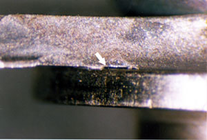
From these observations, the axial compressor diffuser assembly
and the second stage turbine rotor were selected for further
examination.


