Technical Analysis Report " Short Bros. SD360-300, VH-SUM
EXECUTIVE SUMMARY
On 13 August 2000, a Shorts SD-360 aircraft (VH-SUM) sustained
an in-flight shutdown of the right engine, which was later
attributed to the seizure of the gas generator and power sections
of the turbine.
Further examination of the engine by the ATSB and Pratt &
Whitney Canada showed the seizure to have stemmed from the distress
and severe overheating of the engine number one bearing in the
compressor section.
Despite the degree of damage to the bearing races, evidence of
electrical arcing damage was found on the inner race (non-thrust
side) and was subsequently traced back through the accessory
gearbox components to the starter-generator input shaft.
Intermittent pitting on the starter-generator drive gear and
continuous pitting on the driven gear indicated the primary source
of electrical potential was within the starter-generator
assembly.
Recommendations for safety action stemming from this examination
include the further study and testing of the PT6A-67R
starter-generator and engine assembly to determine the conditions
under which excessive current leakage could result. It was also
recommended that the assembly, as installed within VH-SUM be
examined to identify the potential influence of other electrical
accessory items fitted.

FACTUAL INFORMATION
Introduction
On 13 August 2000, a Shorts SD360-300 aircraft VH-SUM sustained
an in-flight uncommanded feathering of the right propeller. The
engine was shut down immediately. Examination of the engine showed
the gas generator and power sections of the engine to have
seized.
Pratt & Whitney Canada (Australasia) subsequently
disassembled the engine. The findings of the teardown examination
are presented in Pratt & Whitney report number 25885.
To support the investigation of the occurrence, the ATSB carried
out an analysis of the following components from the failed
engine.
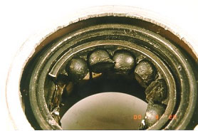
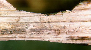
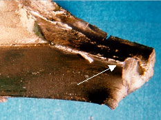
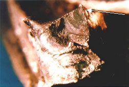
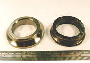
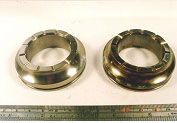
- Number-1 bearing and debris. The outer race of the bearing
remained within the inlet case (figs. 1 & 2). - Gearbox input shaft and roller bearing assemblies (fig.
3). - Coupling splined hollow shaft (fig. 3).
- Starter gear and roller bearing assemblies (fig. 3)
In addition, an unused bearing identical with the engine
number-1 bearing was supplied, as well as copies of reports
prepared by Pratt & Whitney addressing previous engine failures
experienced by the operator.
Component history
The history of the engine was reported as follows (Pratt &
Whitney Canada report #25885).
Serial Number: 106223
Time Since New: 6410.9 hrs
Time Since Overhaul: 1500.1 hrs
Cycles Since New: 9704
Cycles Since Overhaul: 2463
Previous Workshop Visit: 5 June 1999 for routine
overhaul
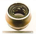 |
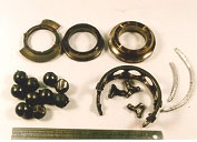 |
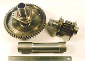 |
|
Figures 1, 2 & |
||
ANALYSIS
Visual examination
Number-1 Bearing:
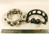
Figure 4 shows the general condition of the bearing as recovered
from the engine. All surfaces of the bearing as well as the nearby
casing showed heavy discolouration and blackening that is typical
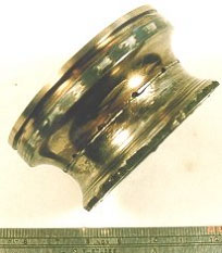
of extreme overheating. All the balls and the inner race (fig. 5)
showed heavy localised wear and metal flow, signalling the sliding
contact of the balls against the inner race.
|
Figures 4 & 5. |
|
The effects of thrust loads within the operating engine had
produced a bias in the wear on the inner race toward the rear inlet
casing. Resulting from this loading and the amount of wear
experienced, the inlet case of the turbine had come into contact
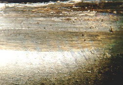
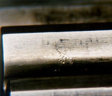
with the adjacent compressor rotor disc. Closer study under the
stereomicroscope showed fine pitting towards the inner edge of the
non-thrust inner race (fig. 6), although scoring marks obscured
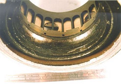
much of this. Damage to the outer race was equally severe, with
heavy indentation and bruising of the contact surfaces from the
ingress of debris (fig. 7).
|
|
|
|
Figures 6 & 7. |
|
The bearing cage had experienced multiple radial cracks and
cracks around the circumference, with most associated with galling,
scoring and other evidence of metal to metal surface contact (fig.
8).
|
Figure 8. Contact |
Some internal corners of the cage showed shallow fatigue cracks
- these had started at areas of heavy surface scoring and metal
flow (fig's. 9 & 10).
|
|
|
|
Figures 9 & 10. |
|
When compared with the new item, the extent of the damage to the
bearing parts was clear (figs. 11, 12 & 13).
|
|
|
|
|
Figures 11, 12 & |
||
Associated components:
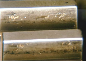
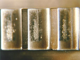
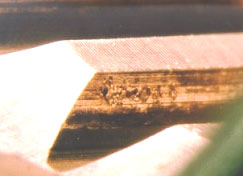
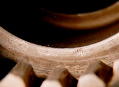
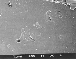
The coupling gear, starter gear and coupling shaft each showed
varying levels of gear surface and spline pitting damage. Mostly,
the pitting was restricted to localised spots at the gear teeth
pitch-line (figs. 14, 15 & 16), although the starter gear
showed uniform damage over the whole contact surface (fig. 17).
|
|
|
|
Figures 14 & 15. |
|
|
|
|
|
Figures 16 & 17. |
|
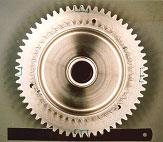
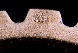
Studying the overall distribution of pitting on each item
revealed the large diameter starter gear showed the most
significant damage over two or three teeth in four equally spaced
regions around the circumference (fig. 18). The smaller coupling
gear which mates with this item showed no suggestion of this
intermittent pitting, with damage found uniformly around the entire
circumference.
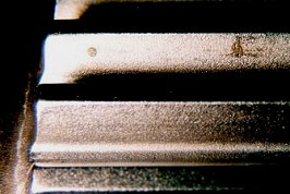
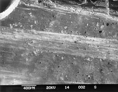
The male and female splined connections showed pitting over both
the teeth faces (figs. 19 & 20) and end surfaces (figs. 21
& 22), with the damage appearing similar in all cases.
|
Figure 18. Starter |
|
|
|
|
Figures 19 & 20. |
|
|
|
|
|
Figures 21 & 22. |
|
Electron microscopy
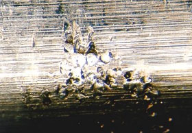
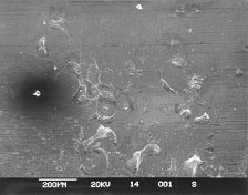
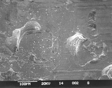
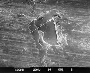
Electron microscope imaging of the pitting identified on the
internal bearing race and gear teeth showed many of the pits to
have a semicircular form, with a shallow concave profile.
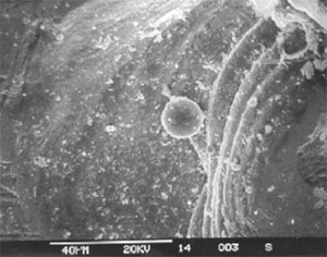
Observation at higher magnifications found evidence of localised
melting, which presented as small balls of metal within the pit
confines. Many of the pits showed a distinctive flattened
appearance - typical of the effects, produced by normal rolling
surface contact. Figures 23 through to 28 show the typical
appearance of the surface pits at various magnifications.
|
|
|
|
Figures 23 & 24. |
|
|
Figure 25. Globules |
|
|
|
|
Figures 26 & 27. |
|
|
Figure 28. Closer |
Metallographic examination
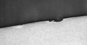
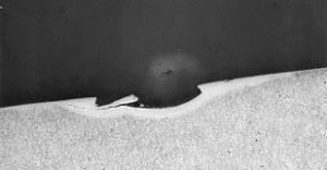
Sections for microscopy were taken through a pitted area on the
less damaged, non-thrust section of the inner race and prepared
using conventional methods. Etching with a 2% Nital solution
revealed several regions along the contact surfaces that displayed
locally transformed, untempered martensite associated with the
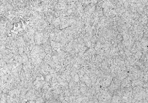
pitting and extending to around 60mm in depth (figures 29 &
30). The general microstructure of the bearing race was fine,
lightly tempered martensite with areas of globular massive carbide
randomly throughout (figure 31).
|
Figure 29. |
|
Figure 30. Closer |
|
Figure 31. General |
Hardness tests
The parent metal hardness, as measured away from the pitted
surface was around 804 - 810 HV30.
CONCLUSION
Material and manufacture
The number-1 bearing inner race (non-thrust section) showed a
microstructure and hardness level that was acceptable for the item
and contained no obvious deficiencies that could have affected the
bearing's service performance.
Engine failure
The breakdown of the PT6A-67R engine (S/N 106223) as installed
within the aircraft VH-SUM was attributed to the failure of the
number-1 turbine bearing. The bearing had experienced severe
frictional damage and overheating, stemming from the seizure of the
balls and the sliding contact against the inner race surfaces.
Because the bearing carried a degree of rearward compressor axial
thrust loading, the front inner race experienced most of the severe
wear and scoring, leaving the rear race comparatively undamaged and
able to be closely studied.
Development of the breakdown
Electron microscopy of the non-thrust inner race showed evidence
of pitting that resembled damage produced by electrical arcing.
Subsequent metallographic examination verified the damage;
revealing localised thermally affected regions associated with the
surface pits. In the presence of such physical and metallurgical
discontinuities, rolling contact fatigue cracking developed and
larger spalled areas formed over the contact surfaces. Increases in
friction stemming from the spalling and the generation of metallic
debris would have raised the vibration and temperature levels,
eventually resulting in the thermal runaway of the bearing and the
seizure as experienced. Such findings concur with the results of
previous examinations conducted on PT6A-67R engines by Pratt &
Whitney Canada.
Source of the electrical current
Several other components in the accessory gear train showed
electrical arcing effects. The damage was found chiefly around the
contact points between the gear teeth. The large diameter starter
gear showed four evenly spaced regions around the circumference
where the pitting was most severe. In contrast, the smaller mating
coupling gear showed uniform pitting around the diameter. This
observation led to three direct conclusions -
- The electric current flowed from starter gear, through to the
coupling gear and into the bearing via the turbine shaft and inner
races. - The electric current was steady or continual and not a
transient surge. - The current was of an alternating or pulsed nature at a
frequency equal to four times the rotational speed of the starter
gear.
From the general design of the engine, it appeared that the most
likely source of the current was from the starter-generator unit,
as the unit coupled directly to the large diameter starter gear.
Armature leakage current from the unit would have conducted via the
frictional coupling; through to the starter gear and into the
bearing via the coupling gear, shaft and turbine shaft.


