Interim report released 18 October 2023
This investigation is being conducted under the Transport Safety Investigation Act 2003 (Commonwealth) by the Office of Transport Safety Investigations (New South Wales) on behalf of the Australian Transport Safety Bureau in accordance with the Collaboration Agreement.
The occurrence
Victoria
On the morning of 25 August 2022, train no. 4MB9 from Altona, Vic. to Bromelton, Qld was prepared for traffic at SCT Logistics’ yard in Altona. The train consisted of locomotives SCT 013 and SCT 005, hauling 1,676 t consisting of 27 freight wagons. The first rostered crew for 4MB9 commenced duty at 0300 hours[1] and consisted of an SCT Logistics employed mentor driver and, an SCT Logistics driver who was learning the route from Altona to Wagga Wagga (521.160 km),[2] NSW.
Marshalled directly behind locomotive SCT 005 was a container wagon on which a single fuel tanker was placed. The fuel tanker was provided for the purpose of in-line fuelling[3] the locomotives enroute to the train’s destination of Bromelton, Qld. The mentor driver performed the task of connecting the fuel lines, multiple unit cable and main reservoir air supply between the locomotives and the fuel tanker. Once connected, the mentor driver tested the ‘fast pump’ and ‘gravity feed’ fuelling modes were operating between the fuel tanker and locomotives.[4]
After preparations were complete, 4MB9 departed Altona Yard about half an hour behind schedule at 0418. The delayed departure was due to track maintenance activities taking place on the Melbourne Metropolitan Network.
Four hours after departing Altona, 4MB9 arrived at Barnawartha, Vic. where a shunt was required to both detach and attach wagons before the train continued north (Figure 1).
Figure 1: Northeast line to Victoria / New South Wales border
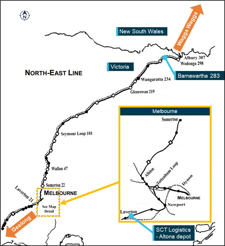
Distances measured from Southern Cross station in Melbourne, Vic.
Source: ARTC, annotated by OTSI
While shunting at Barnawartha, the mentor driver elected to commence gravity feeding fuel from the in-line fuelling tanker to SCT 005. While the fuel usage by the locomotive had been minimal since departure from Altona, the mentor driver advised OTSI that they did this to assist the second rostered crew, who would be taking over the train at Wagga Wagga, NSW (521.160 km).
At 0859, 4MB9 departed Barnawartha, crossing the border into NSW shortly afterward.
New South Wales
At 0934, SCT Logistics’ LiveRun train coordinator contacted the driver’s assistant (second crew) who was to take over 4MB9 at Wagga Wagga. This crew, consisting of a driver and driver’s assistant, were employed by Momentum Rail to operate the SCT Logistics train. They were to take the train from Wagga Wagga to Leightonfield (Sydney), where they would change with a third crew, also employed by Momentum Rail. The train coordinator requested that the driver’s assistant (second crew) check that the in-line fuelling system was operating on 4MB9 and to report back. This gave SCT Logistics the opportunity to arrange manual fuelling of the locomotives by a road tanker on arrival at Leightonfield if required, in the event the in-line fuelling system was not working.
In interview, the mentor driver (first crew) told OTSI that as 4MB9 approached Wagga Wagga, they contacted the outbound driver’s assistant (second crew) by phone to advise that SCT 005 was in the process of being gravity fed fuel by the in-line fuelling system.
As a result, on arrival of 4MB9 at Wagga Wagga at 1052, the driver’s assistant (second crew) checked the fuelling status of SCT 005 and found the locomotive’s tank was full, with excess diesel fuel overflowing onto the track. The driver’s assistant switched off the valve between the fuel tanker and the locomotives, and isolated SCT 005 from the in-line fuelling system to stop the re-fuelling process. Prior to departure from Wagga Wagga, the driver’s assistant contacted the train coordinator to advise that gravity feed mode was working, with SCT 013 to be fuelled at a later stage. The train coordinator asked that the driver’s assistant verify that ‘fast pump’ mode was also operational when able to do so.
At 1101, on completion of the SCT Logistics / Momentum Rail crew changeover, 4MB9 departed Wagga Wagga for Leightonfield (23.700 km).
At 1256, the driver of 4MB9 stopped the train briefly at Harden (385.637 km) (Figure 2) to allow the driver’s assistant to setup the in-line fuelling system to fuel the front locomotive (SCT 013). In interview, the driver’s assistant told OTSI that at this time they opened the valve on the fuel tanker and depressed the in-line fuelling manual override button on SCT 013, to commence the gravity feed process.
Figure 2: NSW Main South Line – Goulburn to Wagga Wagga
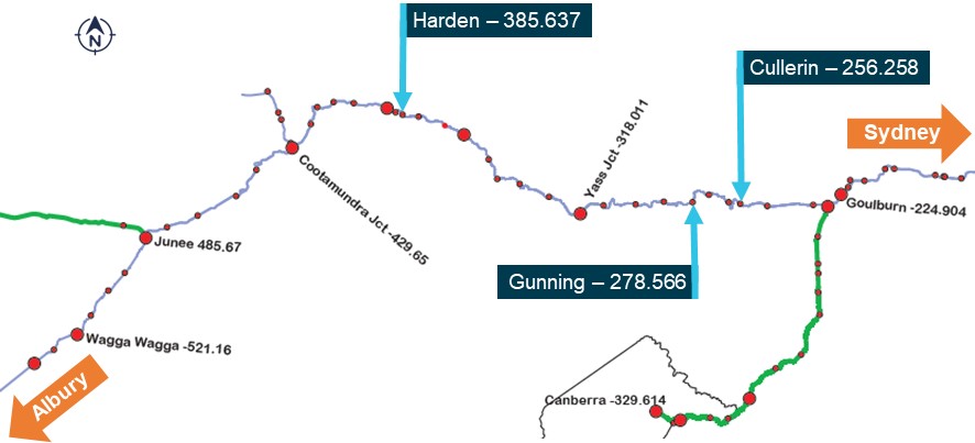
Distances measured from Central station in Sydney, NSW.
Source: UGL Regional Linx, altered and annotated by OTSI
Although SCT 013 was fitted with a fuel sensor which relayed the volume of fuel in the locomotive fuel tank to the FIRE screen[5] on the driver’s console, the driver’s assistant advised this was inaccurate and not relied upon. As a result, at 1402 the driver stopped 4MB9 briefly at Yass Junction (318.011 km) (Figure 2) to allow the progress of the gravity fed fuelling to be checked. At this time, both the driver and driver’s assistant left the locomotive cabin to individually check the physical fuel gauges on each side of SCT 013’s fuel tank.[6]
After departure from Yass Junction, it is likely that the driver continued to monitor the fuel volume on SCT 013 via the electronic reading on the FIRE screen.
Accident sequence
As the train approached Gunning (278.566 km) (Figure 2), the driver swapped positions in the locomotive cabin with the driver’s assistant, allowing them to drive the train. As the driver’s assistant was soon to commence formal training[7] to progress to a driver’s role, this opportunity allowed them additional practical experience in operating a train.
At 1448, after departing Fish River (271.021 km), a lengthy uphill gradient commenced to the Cullerin Road overpass (258.845 km) (Figure 3). The driver instructed the driver’s assistant to select full traction power (8 notches) and to maintain that setting for the ascent of the grade.
Figure 3: Vicinity of the accident
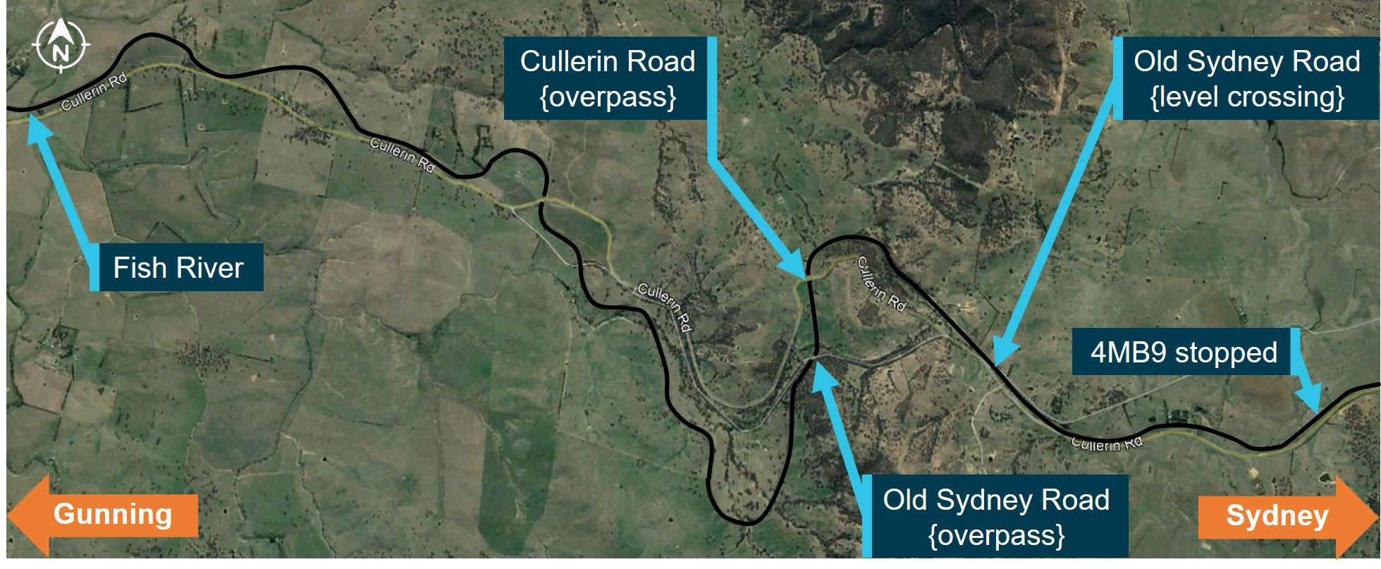
The section of ascending track from Fish River to Cullerin Road overpass and final stopped location of 4MB9. The route of the railway line is depicted by a black line in the image.
Source: Google Earth, annotated by OTSI
As 4MB9 ascended the grade, the in-cab conversation between the driver and driver’s assistant turned to the progress of the in-line fuelling of SCT 013. Although the gravity feed had now been operating for about two hours, the 10,000 L capacity fuel tank on SCT 013 was only reading a fuel volume of about 5,600 L.
In interview, the driver’s assistant told OTSI that the driver of 4MB9 (who was now seated in the driver’s assistant seat) advised that they would temporarily leave the locomotive cabin to check the in-line fuelling circuit breakers in the vestibule. At 1459:36, while travelling at 61 km/h, 4MB9 passed under the Cullerin Road overpass and it was at this location that the driver’s assistant recalled the driver leaving the cabin and entering the vestibule.
From the Cullerin Road overpass to Old Sydney Road level crossing (256.489 km), the gradient changed from uphill to a dip, requiring the driver’s assistant to temporarily reduce the traction power setting.
At 1501:22, 4MB9 now travelling at 74 km/h, passed over the Old Sydney Road level crossing, from which point the gradient changed to a predominantly downhill grade for the next 4 km. The driver’s assistant reduced the locomotive’s traction power to idle at this time. As the driver’s assistant required instruction on operating the train through this area, they left the cabin to find the driver who had not yet returned. When the driver’s assistant could not locate the driver in the vestibule, they opened the external door to check the right-hand side exterior of the locomotive and then the left-hand side exterior. It was while checking the left-hand side exterior that the driver’s assistant located the driver incapacitated, lying across the top handrail and up against the locomotive traction motor blower shroud (Figure 4). The driver’s assistant moved the driver from the handrail and laid them down onto the footplate, at which point they identified the driver had received a fatal head injury.
Figure 4: Location of driver (example locomotive)
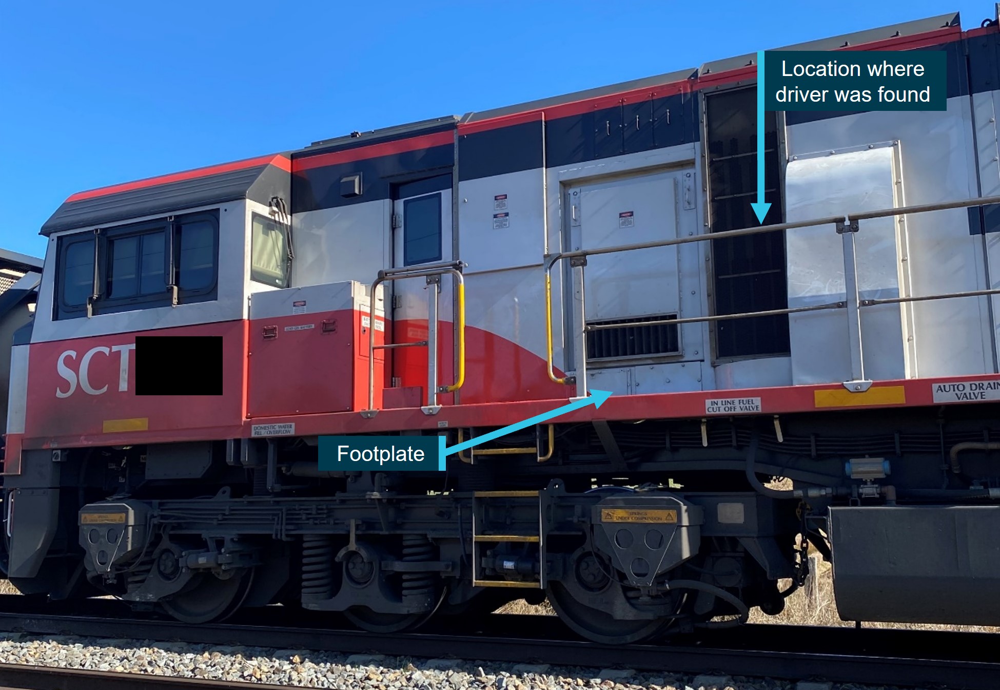
Note: the image is of an example locomotive, not the actual locomotive involved in the accident.
Source: NSW Police, annotated by OTSI
The driver’s assistant immediately returned to the locomotive cabin and shortly afterward applied full dynamic braking.[8] At 1503:09, with 4MB9 now travelling at 88 km/h, the driver’s assistant applied a ‘full service’[9] brake application.
At about 1504, the driver’s assistant made an emergency brake application and placed an emergency radio call to the network control centre. They advised the network control officer that 4MB9 had been involved in an accident and that the driver had been fatally injured. The driver’s assistant further advised the network control centre that the driver had been on the outside of the locomotive checking a ‘fuel switch’.
At 1504:28, 4MB9 came to a stop at 253.096 km. Emergency services arrived on scene at 1527.
Post-accident track inspections
Several hi-rail vehicle track inspections were undertaken during the week following the accident to check for lineside obstructions. These were:
- 25 August 2022 (day of the accident): the preceding 15 km over which 4MB9 had travelled.
- 26 August 2022: the preceding 35 km over which 4MB9 had travelled.
- 1 September 2022: the preceding 100 km over which 4MB9 had travelled.
During these inspections, no object was identified as the cause of the driver’s fatal injury.
Context
Network
The section of track from Gunning to Cullerin was managed by the Australian Rail Track Corporation. Network control services were provided by its control centre at Junee, NSW.
Train crew information
The driver commenced with the Public Transport Commission (railways) in 1973, later qualifying as a train driver. After working for several rolling stock operators, the driver joined Momentum Rail in December 2017. The driver was assessed as medically fit four months prior to the accident.
The driver’s assistant worked as a truck driver for 7 years before joining the rail industry. They qualified as a driver’s assistant in December 2020. After working as a labour hire employee for another rolling stock operator, the driver’s assistant joined Momentum Rail in September 2021. The driver’s assistant was assessed as medically fit in November 2020.
In-line fuelling
General
In-line fuelling (ILF) was a method of fuelling locomotives enroute without stopping the train. Its purpose was to reduce dwell times, reduce staff interaction with fuelling equipment and realise cost-savings through the bulk-buying of fuel from a single source.
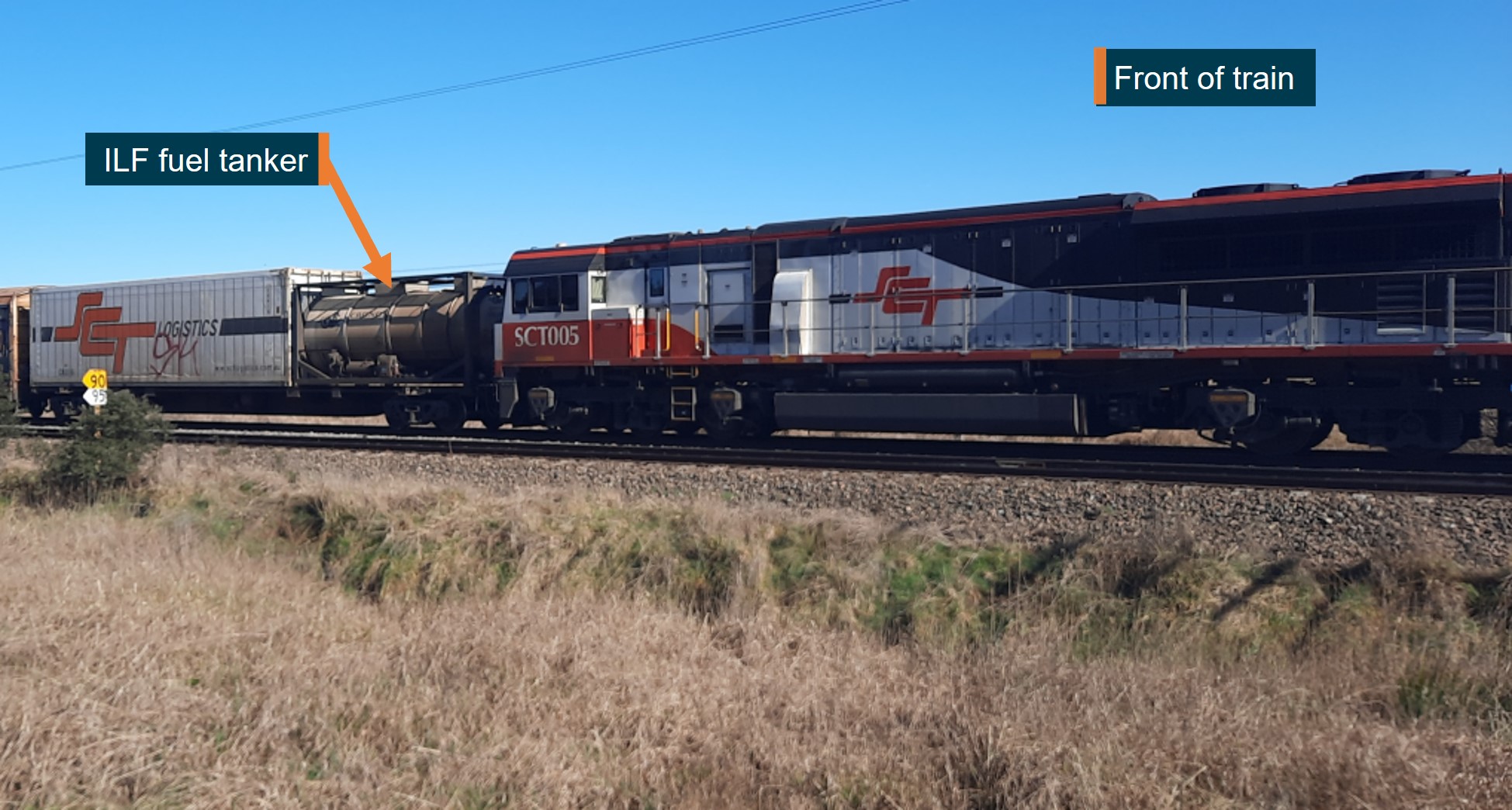
SCT Logistics operated ILF on the east-west corridor between Adelaide (Penfield), SA and Perth (Forrestfield), WA and, on the north-south corridor between Melbourne (Altona), Vic. and Bromelton, Qld. ILF required the placement of a fuel tanker on a flat container wagon immediately behind the locomotives (Figure 5).
Figure 5: ILF fuel tanker placement
Source: SCT Logistics, annotated by OTSI
Connections between the locomotives and fuel tanker to facilitate ILF were:
- fuel pipe from the tanker to the locomotives to supply diesel fuel
- main reservoir air pressure[10] from the locomotives to the tanker, to run the tanker’s fuel pump and test for fuel line leakages
- multiple unit cable from the locomotives to the tanker for the supply of electrical power.
There were three modes of operation for ILF, which were:
- Automatic mode: setup prior to depot departure, this mode required no further intervention from the train crew. Probes within the locomotive fuel tank would identify if the fuel level was low, at which point the ILF system would automatically commence refuelling the locomotives. Diesel fuel was delivered from the ILF fuel tanker to the locomotive using 2-minute alternating periods between gravity fed fuel (50–60 L/min) and air operated pump, pressurised fuel delivery (180 L/min). Once the probes within the locomotive fuel tank determined the fuel tanks were full, fuel delivery from the ILF fuel tanker was automatically stopped.
- Fast pump mode: used when automatic mode was not working as a quick means to fuel the locomotive/s manually. In this mode, the train crew were required to depress an override button on the locomotive (to open the locomotive’s actuator valve), operate a valve override switch on the ILF fuel tanker and lastly, turn and hold a spring-loaded switch on the ILF fuel tanker. These actions allowed the delivery of air operated pump, pressurised diesel fuel (180 L/min). In this mode the locomotive in-tank fuel level probes were not functional. As such, the volume of fuel in the locomotive fuel tank was required to be monitored as fuel would overflow if the tank was overfilled.
- Gravity feed mode: in the event both automatic and fast pump modes were unavailable, fuel could be gravity fed to the locomotives. In this mode, the train crew were required to depress an override button on the locomotive (to open the locomotive’s actuator valve) and operate a valve override switch on the ILF fuel tanker. These actions delivered gravity fed fuel (50–60 L/min). In this mode the locomotive in-tank fuel level probes were not functional. As such, the volume of fuel in the locomotive fuel tank was required to be monitored as fuel would overflow if the tank was overfilled.
Inspection observations
At the time of the accident, the driver’s assistant advised the network control centre that the driver had been outside on the locomotive’s footplate checking a ‘fuel switch’. It was observed that the location where the driver’s assistant found the driver in an incapacitated state was directly above:
- two ILF cut off valves, which isolated either the locomotive’s fuel tank from the ILF fuel line or, isolated the ILF fuel line from the front locomotive headstock[11]
- the locomotive’s actuator valve (Figure 6).
Figure 6: Location of the driver in relation to ILF equipment (example locomotive)
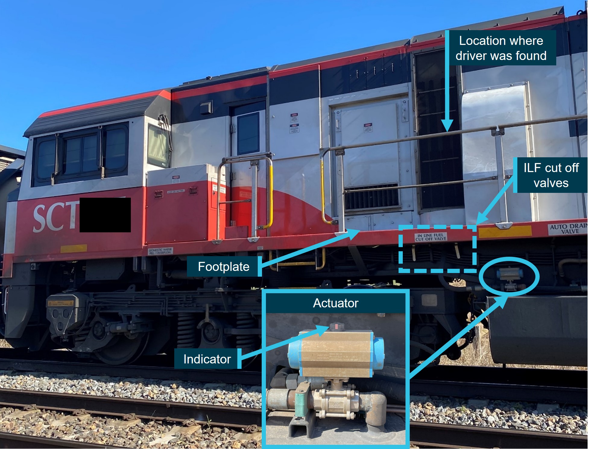
Note: the image is of an example locomotive, not the actual locomotive involved in the accident. In this example image, the locomotive’s ILF cut off valves (dotted box) and actuator (inset image) are depicted in the ‘closed’ position however, these were verified to be ‘open’, consistent with gravity feed mode, on the day of the accident.
Source: NSW Police, annotated by OTSI
After the accident, OTSI investigators attended SCT Logistics’ depot at Altona, Vic. to inspect an exemplar SCT class locomotive and the ILF system. During this inspection, it was found that when standing on the locomotive’s external footplate it was not possible to observe the position of the locomotive’s ILF cut off valves. However, it was found that by leaning hard up against the top handrail and leaning out past the locomotive’s profile, it was possible to observe the indicator located on the top of the locomotive’s actuator.
Safety action
SCT Logistics has taken the following proactive safety action since the accident:
- issued an updated instruction regarding in-line fuelling operational modes and procedures, including restrictions for their use
- issued an updated procedure prohibiting the exit of the locomotive cabin onto the external footplate or, being located outside the profile of the locomotive while it is in motion
- the placement of warning stickers on doors leading from the locomotive vestibule onto the external footplate.
Further investigation
- gathered and undertaken analysis of locomotive event recordings and, network control and LiveRun voice recordings
- inspected the rail corridor and gathered recorded vision of the corridor immediately prior to the accident
- gathered information regarding the in-line fuelling system including its operation, operational modes and procedures
- gathered information regarding accessing the external locomotive footplate during transit, including procedures and training materials
- conducted several interviews with operational staff
- gathered and undertaken analysis of reported lineside obstructions and remedial actions
- reviewed evidence collected at the accident site and during post-accident track inspections.
The investigation is continuing and will include:
- further review of permanent lineside obstructions and proximity to the train’s kinematic envelope
- further review of vegetation management which encroaches the rail corridor
- further review and examination of the reliability of the in-line fuelling system and, rolling stock operator monitoring of modes of operation
- enterprise training for the in-line fuelling system
- consideration of SCT Logistics and Momentum Rail contractual requirements, oversight and shared risk management.
Should a critical safety issue be identified during the course of the investigation, the ATSB will immediately notify relevant parties so appropriate and timely safety action can be taken.
A final report will be released at the conclusion of the investigation.
Purpose of safety investigationsThe objective of a safety investigation is to enhance transport safety. This is done through:
It is not a function of the ATSB to apportion blame or provide a means for determining liability. At the same time, an investigation report must include factual material of sufficient weight to support the analysis and findings. At all times the ATSB endeavours to balance the use of material that could imply adverse comment with the need to properly explain what happened, and why, in a fair and unbiased manner. The ATSB does not investigate for the purpose of taking administrative, regulatory or criminal action. TerminologyAn explanation of terminology used in ATSB investigation reports is available here. This includes terms such as occurrence, contributing factor, other factor that increased risk, and safety issue. Publishing informationReleased in accordance with section 25 of the Transport Safety Investigation Act 2003 Published by: Australian Transport Safety Bureau © Commonwealth of Australia 2023
Ownership of intellectual property rights in this publication Unless otherwise noted, copyright (and any other intellectual property rights, if any) in this report publication is owned by the Commonwealth of Australia. Creative Commons licence With the exception of the Coat of Arms, ATSB logo, and photos and graphics in which a third party holds copyright, this publication is licensed under a Creative Commons Attribution 3.0 Australia licence. Creative Commons Attribution 3.0 Australia Licence is a standard form licence agreement that allows you to copy, distribute, transmit and adapt this publication provided that you attribute the work. The ATSB’s preference is that you attribute this publication (and any material sourced from it) using the following wording: Source: Australian Transport Safety Bureau Copyright in material obtained from other agencies, private individuals or organisations, belongs to those agencies, individuals or organisations. Where you wish to use their material, you will need to contact them directly. |
[1] All time references in this report are in local time (Eastern Standard Time).
[2] All track distances are measured from Central station in Sydney, NSW, unless otherwise stated.
[3] See In-line fuelling for further information.
[4] The three operating modes were ‘automatic’, ‘fast pump’ and ‘gravity feed.’ See In-line fuelling for further information.
[5] FIRE screen: a digital display screen on the driver’s console which provided information to the driver, e.g. speed, air pressures, tractive effort and fuel volume.
[6] To ensure an accurate fuel reading, both physical gauges are checked and the two volume readings averaged to provide an accurate fuel reading. This allows for any locomotive sidewards tilt impacting the fuel volume readings due to track geometry.
[7] This training was scheduled to be an ‘engine and air’ school, i.e. knowledge of locomotives, equipment and the airbrake system.
[8] Dynamic braking is an electrical brake which creates a retarding force by changing the electrical fields in the locomotive’s traction motors from a traction to generator configuration.
[9] Full service is the maximum braking capacity that can be achieved with the train’s airbrake system. Selected by the driver, it applies maximum braking capacity to all trailing wagons on the train.
[10] Main reservoir air was produced by the locomotives’ air compressors. It was used for several of the train’s functions, including the braking system, horn and sanding equipment.
[11] The headstock is at both the front and rear of the locomotive, below footplate level. It is the interface point for air, fuel and electrical connections between the locomotive and other coupled rolling stock.


