
Investigation summary
What happened
On 7 December 2020, at about 1155 local time, SCT Logistics train 1MP9 was travelling on the Australian Rail Track Corporation (ARTC) network through Adelaide, South Australia en route to the SCT Logistics Penfield freight facility.
As the train traversed a slight left curve in the southern approach to the Torrens Road level crossing the driver saw that road traffic was still passing over the crossing about 90 m ahead, and that the level crossing warning equipment had not operated for the approach of the train. The driver initiated an emergency brake application before continuously sounding the locomotive horn, warning road traffic of the train’s approach. Shortly after, the locomotive entered the level crossing and continued to travel a further 260 m before stopping. The trailing freight wagons from the train stopped on the level crossing and blocked the passage of road traffic. There was no collision with road traffic or injury to any person.
What the ATSB found
The ATSB found that, earlier that day members of a subcontracted signal team working on the adjacent Adelaide metropolitan passenger rail network (AMPRN) had undertaken temporary wiring alterations to the control circuits of 2 level crossings to facilitate track tamping work. A late change to the scope of track work required the signal team to undertake additional work to alter the control circuits at another level crossing located at Torrens Road. This scope change placed an increased work demand with short notice on the signal team to implement the pre-approved Torrens Road inspection and test plan procedure. The procedure required the installation of 3 temporary jumper wires, 2 of which were superfluous. The inclusion of avoidable wiring placed an unnecessary task demand on the signal team during the wiring installation stage.
Following the installation stage, the signal team tested the temporary wiring for compliance to the inspection and test plan. The methodology adopted by the signal team did not ensure independence between the installation and testing tasks. This resulted in a wiring error not being corrected and remaining in the Torrens Road level crossing control circuit as a latent condition that could affect the correct operation of the level crossing warning equipment.
The uncorrected wiring error, combined with another signalling system condition that later presented on the AMPRN, resulted in the control input from the ARTC network signalling system not activating the Torrens Road level crossing warning equipment for train 1MP9 as it approached the crossing.
The ATSB established that the inspection and test plan that was used by the signal team did not include effective test procedures to verify and validate the safety integrity of the level crossing control circuits following the installation of the temporary wiring alterations. The South Australian Public Transport Authority reviewed and approved a package of level crossing inspection and test plans developed by their principal contractor, Acciona, which did not specify any requirement to test the altered wiring following installation. The effectiveness of any testing undertaken to control risk and assure the safety integrity of the rail infrastructure for trains operating on the ARTC network relied solely on the methodology adopted by the subcontracted signal team on the day.
What has been done as a result
Following the incident, Acciona undertook a risk assessment of the level crossing alteration works in consultation with the project stakeholders. New controls associated with works were incorporated into an updated construction work method statement that was subsequently submitted to the South Australian Public Transport Authority for approval. The controls addressed requirements for additional function testing activity and the potential for road closures where wiring alterations were required to facilitate track tamping work.
In December 2020, the Office of the National Rail Safety Regulator (ONRSR) published a notice to rail transport operators highlighting several incidents of the non-operation of level crossings on live lines due to incorrect isolation, and recommended operators ensure the completion of the key tasks specified in the notice.
The Rail Commissioner amended work instructions related to the temporary decommissioning and jumpering of signalling systems. Additionally, the Rail Commissioner worked with the contractor managing the AMPRN to develop improved procedures and forms for use in the temporary alteration of signalling systems.
The ARTC, although not directly involved in the installation of the jumpers at the Torrens Road level crossing, also reviewed and updated several ARTC engineering standards related to the modification of control circuitry of level crossings that were shared between operators.
Safety message
The correct operation of the active warning equipment installed at level crossings forms the primary engineered risk control for the management of safety at the road-rail interface. A failure of the level crossing warning equipment to operate on the approach of a train introduces significant risk of a collision that may result in fatalities or serious injury to road users, train passengers and crew.
Any installation or alteration of a signalling system introduces a potential risk to the safety of rail operations that may arise from a design or installation error. To manage the risk, signal designs typically underwent an independent review and approval process and the installed or altered signalling systems were then subjected to various levels of testing, dependent on the complexity of the system change. At a basic level these tests typically involved the certification of the system through the independent verification of the installed wiring followed by the validation of the systems control functions to ensure the safety of rail operations was maintained.
It is essential that rail transport operators and rail safety workers plan, document, and implement effective testing systems and auditable practices to ensure that new or altered safety‑critical railway infrastructure is rigorously verified and validated to assure the safety integrity of the infrastructure being placed into service.
The occurrence
Overview of the track work
On 2 December 2020, Acciona[1] commenced a program of track work[2] on the South Australian Public Transport Authority (SAPTA) Adelaide metropolitan rail network (AMPRN) as part of the Gawler rail electrification project (GREP). The Acciona worksite was located on the Gawler up line[3] between the 2.7 km mark[4] at North Adelaide Station and the 8.5 km mark at Grand Junction Road, located north of Islington Station (Figure 1 ,detailing the stations within the work area). The Australian Rail Track Corporation (ARTC) interstate rail line ran parallel to the AMPRN through the worksite and was protected by the AMPRN level crossing warning equipment at each road crossing location.
Figure 1: Acciona Gawler rail electrification project worksite
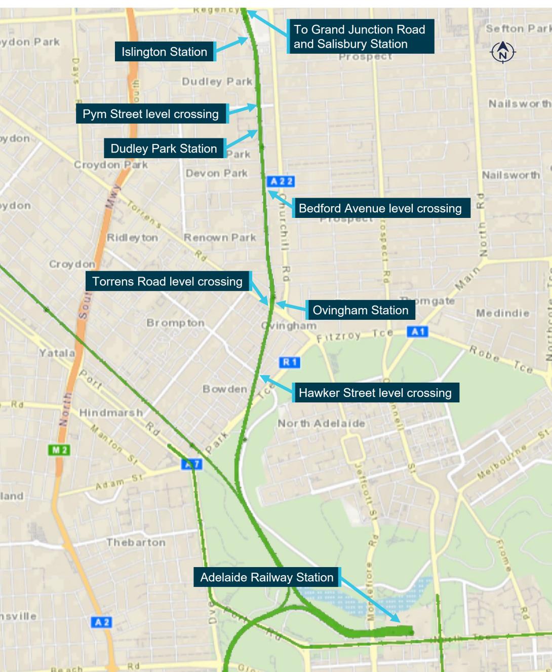
Source: NationalMap, Australian Government, annotated by the ATSB
To facilitate the track tamping work, rail safety workers[5] from Rail Industry Constructions undertook electrical work on the AMPRN signalling system under a subcontract to Acciona. The electrical work involved the removal of track circuit[6] connections from the rails and if required, the installation of temporary jumper wiring to the control circuit of a level crossing that would be affected by the removal.
The Gawler up and down rail lines were closed to scheduled passenger services and the jumper wiring was to prevent the unintended operation of the level crossing flashing lights, gongs and boom barriers due to the track work on the AMPRN. On completion of the track work each day, the signalling system was reinstated to the original state.
The ARTC interstate rail line was open to train services and normal operation of the level crossing warning equipment was to be maintained for a train travelling on that line.
Prior to the arrival of train 1MP9
4 December 2020
On the morning of 4 December 2020, the Rail Industry Constructions rail safety workers comprised a tester in charge (TIC), a signal electrician and 2 trade assistants (signal team). The team attended the daily Acciona pre-work briefing where the TIC spoke with the Acciona possession protection officer (PPO) and other Acciona project representatives to determine the scope of the team’s work for that day. The agreed work involved the removal of connections from the rails and alterations to the Pym Street and Belford Avenue level crossing control circuits.
Following the briefing, the TIC and signal electrician travelled to the Islington relay room, located around 500 m north of the Islington station, and used the pre-approved inspection and test plans (ITPs) to install and test the alterations to the 2 level crossings. On completion of this work, they moved from the relay room to the rail track where, in conjunction with the remainder of the signal team, they removed the required connections from the rails in preparation for the track work to commence.
At the end of the track work for that day, the signal team reinstated the connections and tested the track circuits. The TIC and signal electrician then went to the Islington relay room to remove the jumpers from the 2 level crossing control circuits before testing the correct operation of the associated warning equipment, as per the respective ITP.
7 December 2020
On 7 December 2020, at about 0630 local time, the signal team attended the routine Acciona pre-work briefing. The scope of the work for the day was to again remove connections from the rails and alter the Pym Street and Belford Avenue level crossing control circuits. The TIC recalled that during the pre-work brief, the Acciona work group supervisor asked them to remove as many of the connections from the rails that they could toward the Dudley Park station.
The TIC and signal electrician travelled to the Islington relay room to alter the control circuits for the 2 level crossings. At about 0805, the TIC and signal electrician completed work and moved to the track to remove the connections from the rails between the Islington and Dudley Park stations, as they had done on the previous days.
At about 1020, the signal team completed that work. Shortly after, the work group supervisor asked the TIC if they would also undertake alterations to the Torrens Road level crossing control circuit and remove additional connections from the rails, so that work could continue past Dudley Park station towards Torrens Road.
Although this work was not planned during the pre-work briefing, the TIC stated they felt an obligation to comply with the request and undertake the additional tasks, so the work group could recover from previous delays in their schedule. The TIC felt the signal team was under constant pressure to complete tasks and there was not an understanding from the tamping workgroup of the time needed to undertake the signal works. The TIC stated they agreed to the request on the proviso that the track work up to Dudley Park station be completed so that the signal team could start to reinstate the connections to the rails in preparation for testing the correct operation of the track circuit.
At about 1032, the TIC telephoned the Acciona PPO to tell them that the track work was progressing well, and the work group would likely reach the Torrens Road level crossing later that day. The TIC also told the PPO they had agreed with the supervisor of the work group to expand the signal team’s scope of work to include the alteration of the Torrens Road level crossing control circuit. The TIC reached agreement with the PPO that they would first undertake the alteration of Torrens Road control circuit, before meeting with them to provide a completed infrastructure booking advice form (IBA).[7]
At about 1045, the TIC told the signal electrician of the change to the scope of work and that they would now install jumpers at Torrens Road, before returning to remove the additional track connections between Dudley Park and Ovingham stations. Shortly after, the TIC and signal electrician arrived at the Torrens Road level crossing and accessed the location case that housed the level crossing control circuit.
The TIC and signal electrician positioned themselves at the front (Figure 2) and rear (Figure 3) of the location case (Loc 472) respectively to begin installation of the jumpers. The TIC kept the ITP, as was their usual practice, and called instructions to the signal electrician on where to connect the ends of each jumper wire. The ITP circuit diagram required 3 jumper wires to be installed. The TIC marked off the installation of each corresponding connection on the ITP as the work progressed.
The rear view of location case 472 shows the temporary jumper wiring (red). The installation method for the jumper wiring was intended and meant to make temporary wiring conspicuous from other wiring installed at that location.
Figure 2: Torrens Road location case (Loc 472) front view
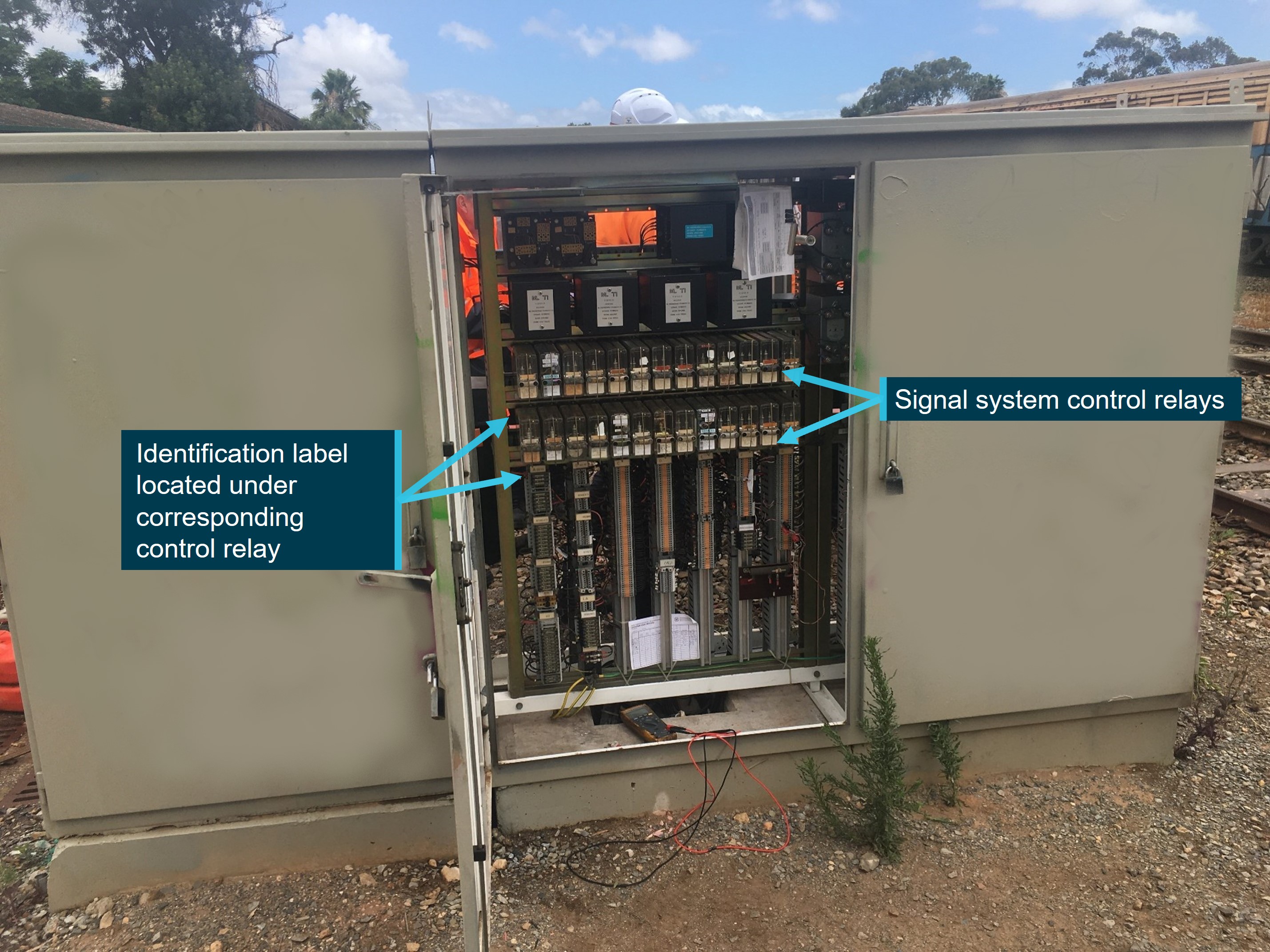
Note: Location case 472 showing signalling control equipment, image modified by ATSB to annotate and remove graffiti tags from exterior of location case. Source: Acciona, annotated by the ATSB
Figure 3: Torrens Road location case (Loc 472) rear view
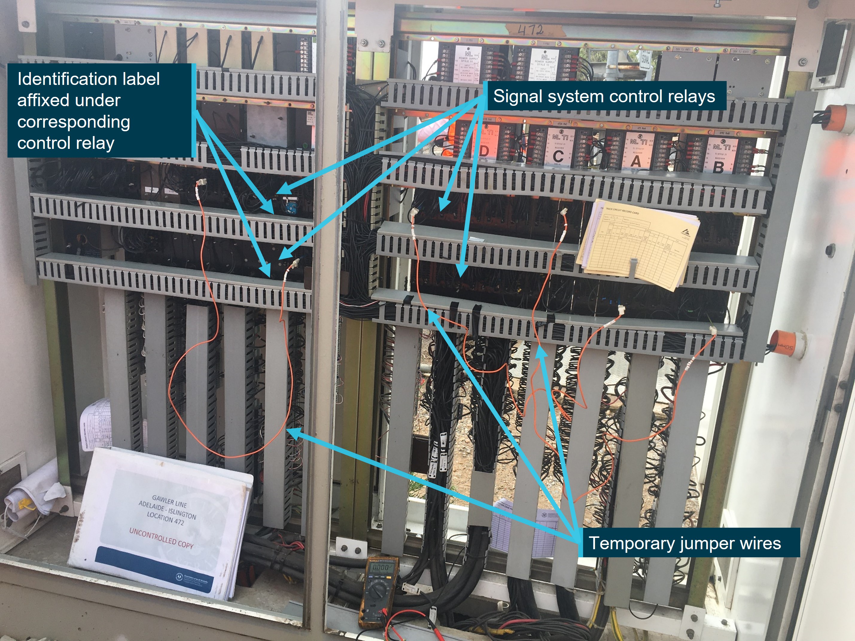
Source: Acciona, annotated by the ATSB
Following the installation of all the jumpers, the TIC operated the test switch[8] to check the correct operation of the level crossing warning equipment. The warning equipment functioned as the TIC expected.
The TIC and signal electrician then left the Torrens Road level crossing location. The TIC went to meet the PPO to complete the IBA. The signal electrician went to the track and met with the 2 trades assistants in readiness to remove the electrical connections from the rails.
At about 1120, the TIC and PPO completed the IBA for the work to the Torrens Road level crossing. Shortly after, the TIC contacted the signal electrician by telephone informing them that the IBA was complete, and they could commence removal of the connections from the rails.
During this work, connections to 572C track located between the Dudley Park and Ovingham stations were removed. The removal of the track connections caused an associated relay in the level crossing control circuit for the Torrens Road level crossing to also de-energise.
Arrival of train 1MP9 at Torrens Road level crossing
At about 1155, SCT Logistics train 1MP9, travelling on the ARTC rail line, occupied the Torrens Road level crossing southern approach circuit. The ARTC signalling system detected the train and sent a control input to the AMPRN Torrens Road level crossing control circuit to activate the warning equipment. The warning equipment did not activate in response to the ARTC control input. The train, travelling at a speed of 44 km/h continued to approach the Torrens Road level crossing.
At about 1156, as the train rounded a slight left curve about 90 m before the Torrens Road level crossing, the driver saw that road traffic was still crossing in front of the train and that the warning equipment had not activated. The driver immediately moved the automatic brake handle to the emergency position to apply maximum braking. About 45 m from the crossing the driver started to continuously sound the locomotive horn to warn road traffic of the train’s approach.
Train 1MP9 continued to brake, entered and travelled through the level crossing, narrowly missing a number of road vehicles before the lead locomotive stopped at the 5.25 km mark,[9] about 260 m north of the level crossing. Trailing freight wagons from 1MP9 blocked the Hawker Street and Torrens Road level crossings for the passage of road traffic.
Response to Torrens Road level crossing irregularity
At about 1158, the driver of 1MP9 made an emergency radio call to the ARTC network control officer (NCO) notifying the Torrens Road crossing warning equipment had failed to operate for their train and that there were several near misses with road vehicles as the locomotive passed over the level crossing.[10] The NCO instructed the train crew to remain in situ and wait for the arrival of support personnel to manage safety at the site (Figure 4).
Shortly after the incident, representatives from SAPTA, ARTC, Acciona, the Office of the National Rail Safety Regulator and South Australian Police attended the site. SAPTA representatives coordinated the onsite response, gathered evidence, and commenced an internal investigation.
Rail vehicles from 1MP9 continued to block the Hawker Street and Torrens Road level crossing until about 1505, when, following agreement with SAPTA representatives, the ARTC NCO issued an authority to the train crew to continue their journey to the SCT Logistics Penfield rail freight centre.
Figure 4: Train 1MP9 at Torrens Road level crossing
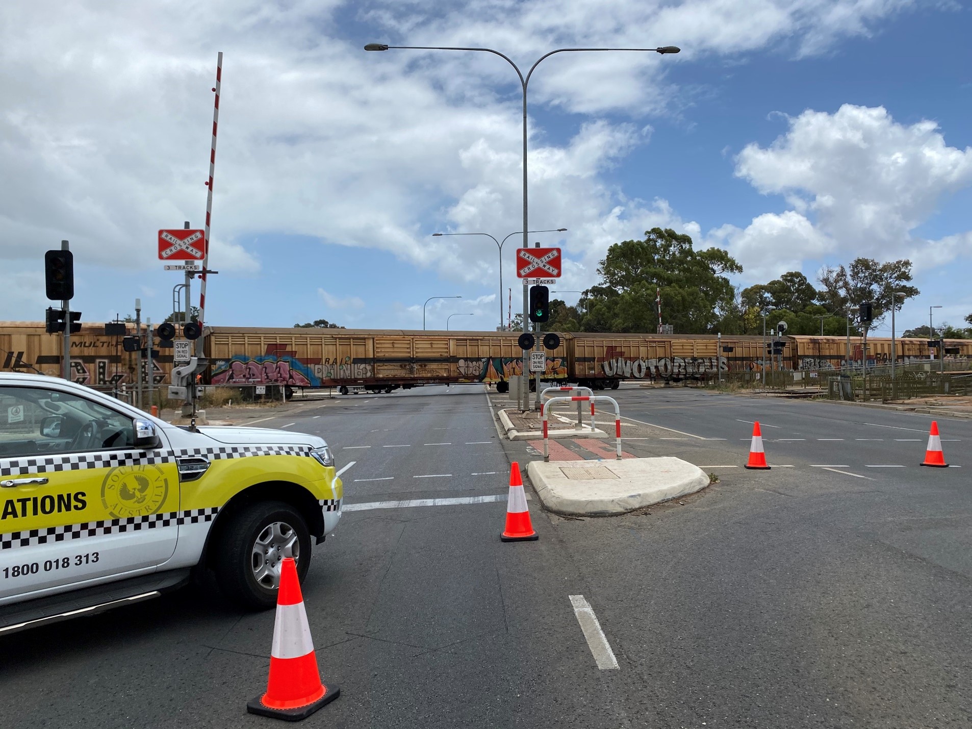
Note: Level crossing south-eastern road approach. Source: Rail Commissioner
Context
Personnel information
Train crew
At the time of the incident, train 1MP9 was crewed by 2 drivers. Both drivers held route competencies that were current for the track section travelled. The health assessments of each driver were current, and they had both met the standard prescribed by the National standard for health assessment of rail safety workers without restriction.
Signal team
The Rail Industry Construction (RIC) signal team comprised the tester in charge (TIC), a signal electrician and 2 trades assistants. The TIC and signal electrician were rail safety workers, assessed to have the required competencies to undertake the rail safety work on the Adelaide metropolitan passenger rail network (AMPRN) signalling system. The statement of competency record for the TIC and signal electrician identified they had around 55 and 45 years of experience respectively undertaking rail safety work on signalling infrastructure. The experience included previous engagements and the successful completion of similar tasks on both the AMPRN and Australian Rail Track Corporation (ARTC) network signalling infrastructure.
The trades assistants were supervised by the TIC or signal electrician and were not qualified to undertake unsupervised rail safety work on the signalling equipment. Neither trades assistant was directly involved with work to implement the Torrens Road inspection and test plan (ITP).
The signal electrician and TIC underwent health assessments as per the requirements of the National standard for health assessment of rail safety worker as a rail safety worker category 1 and 3 respectively. Although there were anomalies with the TIC’s health assessment category and currency, there was no evidence the TIC or signal electrician health assessment categorisation or any physiological condition present at that time influenced the incident at Torrens Road.
In the week prior, the TIC and signal electrician worked between 8.5 and 12 hours each day on the Gawler rail electrification project (GREP) undertaking the signalling alterations to facilitate the track tamping works (see Appendix A – Fatigue risk management program). These hours were generally consistent with the Acciona fatigue management guidelines (10 to 12 hours per day up to a maximum cumulative total of 60 hours per week).
The Acciona Alliance rail safety management plan outlined the procedures put in place to satisfy the accreditation requirements of the Rail Commissioner[11] (RComm). In particular, the competency, health and fitness, and fatigue management programs applicable to the GREP rail safety workers of Acciona, and subcontractor RIC. For additional information related to each program see Appendix A – GREP safety management system procedures.
Train information
SCT Logistics train 1MP9 comprised locomotives CF4430, CF4410 and CSR002 hauling 46 rail vehicles. The train was 1,773 m in length and had a gross mass of 4,561 tonnes. The train was travelling from Dooen, Victoria to the SCT Logistics Penfield rail freight centre near Adelaide, South Australia.
Railway infrastructure
The Australian Rail Track Corporation
The ARTC interstate rail line at Torrens Road consisted of a single standard gauge (1,435 mm) rail track. The track was constructed using continuously welded rails secured to concrete sleepers by resilient fasteners and supported on crushed rock ballast.
The signalling system enabled the bi-directional operation of rail traffic. The system incorporated level crossing controls that functioned independently from the signalling system on the adjacent AMPRN. Rail traffic approaching Torrens Road level crossing on the ARTC rail line triggered a level crossing control, which then provided an input to the AMPRN signalling system to activate the level crossing warning equipment, and the road traffic light signals.
South Australian Public Transport Authority
The AMPRN at Torrens Road consisted of 2 broad gauge (1,600 mm) rail tracks. The tracks were constructed using continuously welded rails secured to concrete sleepers by resilient fasteners and supported on crushed rock ballast.
The Torrens Road level crossing was located on an arterial road near the north-western fringe of the Adelaide central business district. The rail track infrastructure of the AMPRN and ARTC network ran in parallel at that location (Figure 5).
The configuration of the signalling system for the AMPRN enabled passenger rail traffic to principally travel in either an up or down direction[12] on the respective track. The Torrens Road level crossing control equipment could be configured locally[13] to enable the automatic operation of the warning equipment to facilitate single line bi-directional working (with limited functionality). Prior to the implementation of single line bi-directional working, an alternative method of safe working was required for the management of rail vehicle movements.
All rail tracks were protected by flashing lights, gongs and half boom barriers mounted to mast assemblies. In addition, several mast assemblies were equipped with 3 aspect road traffic light signals. The traffic light signals interfaced with the railway level crossing control system and other road traffic light signals at an adjacent road traffic signalled intersection, located about 100 m to the south-east. The traffic light signals controlled the flow of road traffic to prevent queuing of road vehicles across the rail tracks at the Torrens Road level crossing.
The Torrens Road flashing lights, gongs, half boom barriers, and the associated trackside signalling and communication systems were operated and maintained by the South Australian Passenger Transport Authority (SAPTA) under the rail safety accreditation of the RComm.
Figure 5: Road and rail track layout at Torrens Road level crossing
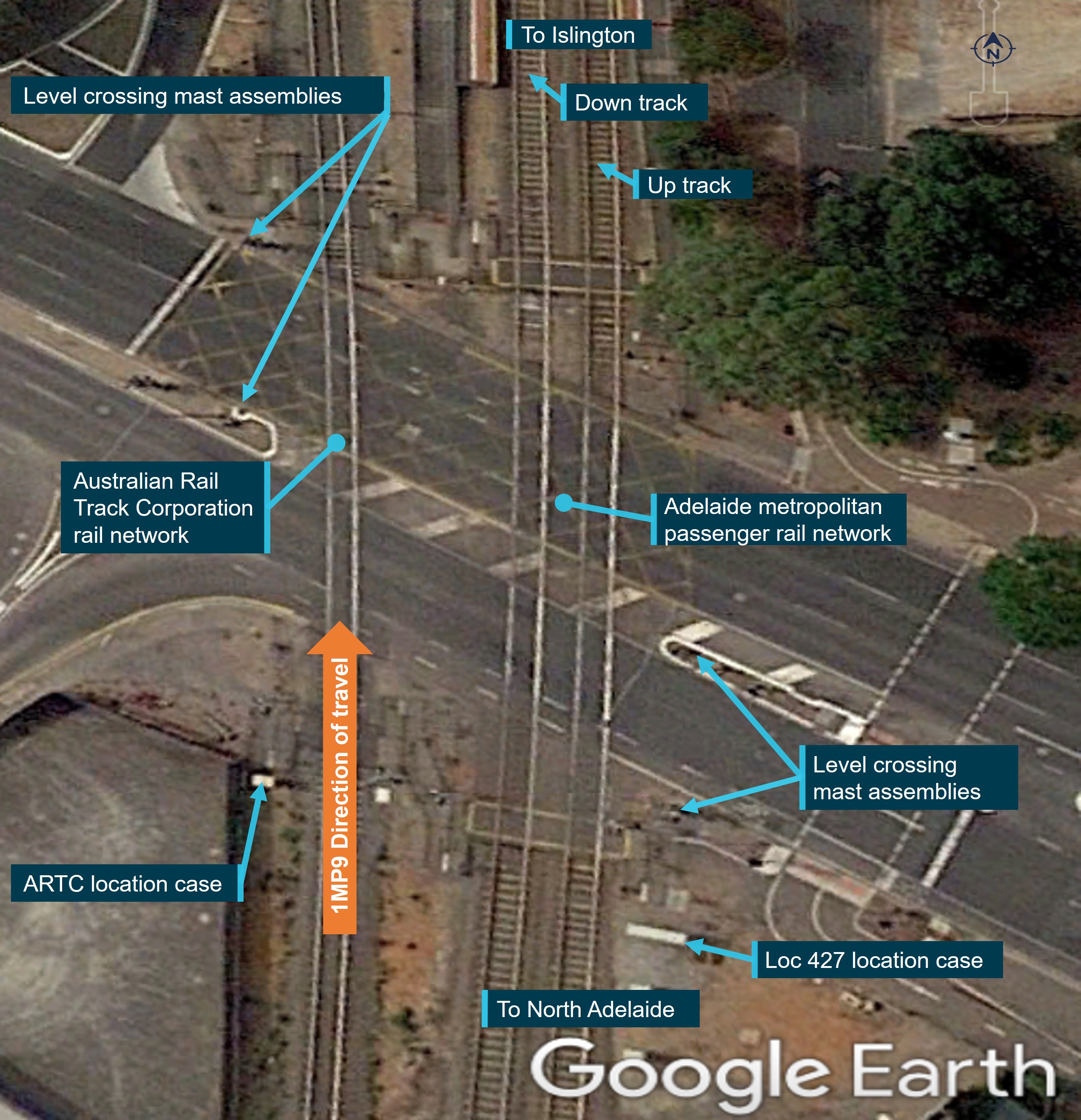
Source: Google Earth, annotated by the ATSB
Gawler rail electrification project
Overview
The GREP works were managed by the South Australian Department of Infrastructure - Transport project delivery (TPD) and undertaken under the RComm rail safety accreditation. The RComm, SAPTA and TPD were all departments or bodies under the South Australian Department for Infrastructure and Transport (Figure 6). Relevant SAPTA safety management system standards, procedures and work instructions for the AMPRN signalling and communications systems were adopted by TPD to manage the GREP works.
Figure 6: AMPRN rail network and GREP project organisation structure
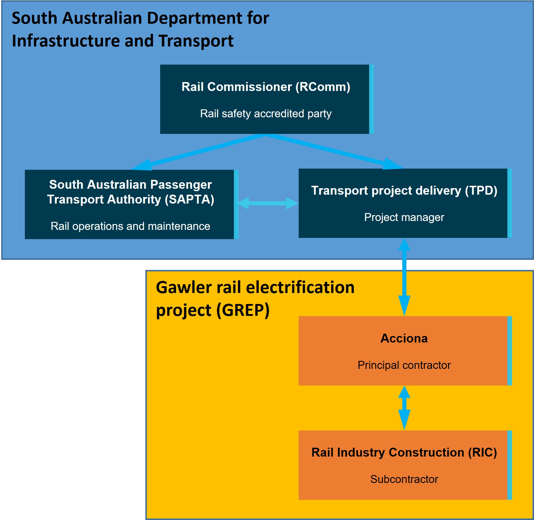
Source: ATSB
The TPD delivered the GREP works through the principal contractor, Acciona, managing the project alliance safety management plan. Acciona initially engaged subcontractor RIC to undertake works associated with the provision of electrical conduits and pits for the project. Acciona later varied the subcontract with RIC to include the provision of qualified rail safety workers to undertake project work as directed by Acciona. Specifically, the alteration and testing of parts of the level crossing control circuitry, and removal and reinstatement of connections to the rails in the areas affected by the GREP track works. The operation of rail maintenance and construction vehicles used in conjunction with the GREP work site was under the Acciona rail safety accreditation as a rolling stock operator. Acciona was not accredited in South Australia as a rail infrastructure manager (RIM).
The roles, responsibilities, authorities, accountabilities and general safety duties applicable to the various parties involved in the contractual arrangements to deliver a rail project, such as the GREP, were outlined in the Rail Safety National Law – South Australia Act 2012 (RSNL) and associated guideline documents published by the Office of the National Rail Safety Regulator and the Rail Industry Safety and Standards Board.
The RSNL incorporated the principles of shared responsibility and accountability in contractual arrangements and highlighted that the management of rail safety was the shared responsibility of everyone involved in undertaking the required rail safety work. The degree to which a person was accountable for rail safety was dependent on the nature of the risk their activities might pose to rail safety. The management of risks associated with railway operations was therefore predominantly the responsibility of the person best able to control them.
Additional information related to the RSNL and guidelines for contracting arrangements are contained under Appendix B – Contracting in the rail industry.
Procedures for temporary signalling system alterations
To manage potential risks to rail operations when undertaking temporary wiring alterations to the level crossing control circuits, RIC developed documentation that defined the project scope and responsibilities, work method statements, and the ITP specific to each level crossing location.
Level crossing inspection and test plan approval procedure
On 23 September 2020, representatives of Acciona, TPD and RIC met to establish the procedure that Acciona would follow to submit the draft ITPs, which included the level crossing control circuit schematic drawings to TPD for approval.
The agreed procedure (Figure 7) required Acciona to submit the draft ITPs for all the affected level crossing locations as a single package. TPD was then to forward the package to SAPTA for review and final approval. Once approved, SAPTA would endorse a network access authority application (NAA) to allow the RIC rail safety workers (the signal team) access to the AMPRN to commence work onsite.
Figure 7: Inspection and test plan approval flowchart
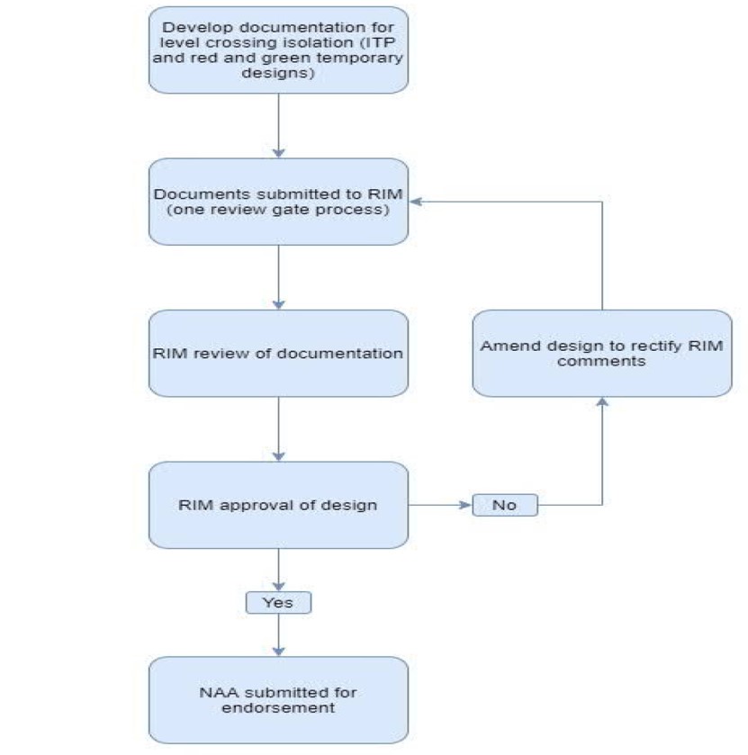
Source: Acciona
During the meeting, TPD identified that the work to isolate (decommission) level crossing functionality was ‘specialised works’ and that the SAPTA procedures for installing temporary wiring, testing, and commissioning activities were to be followed by the signal team.
Although this requirement was identified during the meeting, neither TPD nor SAPTA provided Acciona or RIC with a copy of the SAPTA work instruction WI-AM-SP-1234 Signalling system temporary decommissioning and jumpering or the SAPTA forms FO-AM-SE-1226 Inspection and test plan template and FO-EM-SE-1226 - Amendment log for their reference or use in the development of the GREP signalling procedures for the specialised works specific to the level crossings (see SAPTA signalling system temporary decommissioning and jumpering work instruction).
To develop the draft ITPs, RIC adapted a SAPTA ITP document sourced from a project RIC had previously undertaken for TPD on the AMPRN. The formatting of the ITP document was generally consistent with the SAPTA form FO-EM-SE-1226 and included sections related to the:
- document and version control
- plan approval and the allocation of roles and authority to implement the plan
- master test plan listing in sequential order the equipment and a description of the required task to be undertaken
- certification by the TIC of the tasks and related testing activity that were complete.
RIC representatives also prepared 2 copies of the relevant control circuit diagrams for each level crossing installation. One copy showed the jumpers (marked up in red) to illustrate the required termination point of each wire in the control circuit. The second copy showed the jumpers (marked up in green) to illustrate the wires that must be removed following completion of the track work for that day. A fresh copy of the ITP and circuit diagram package was produced for each occasion where modification of a level crossing control circuit was necessary.
On 25 September 2020, the RIC representatives[14] who had either produced, checked or approved content, signed off on version 1 of the draft ITP for each of the level crossing installations the GREP track work program would affect. Acciona subsequently submitted copies of the draft ITPs by email as a single package to TPD for forwarding to SAPTA for review and final approval, as per the ‘one review gate process’ in the approval flowchart.
Signalling work scope procedure
On 15 October 2020, RIC developed the GREP Tamping project signalling methodology document to describe the scope of work for the project, the network access arrangements and the division of responsibilities between Acciona, RIC and SAPTA for managing the affected signalling infrastructure.
The document specified that RIC would provide suitably competent staff (the signal team), and that prior to the commencement of any site activity, these staff would attend the daily Acciona and PPO pre-work briefings. During the pre-work briefings, RIC staff, in this case the TIC, was required to notify SAPTA maintenance staff and the PPO of the proposed location of work and the tasks to be performed that day. The document also specified that under no circumstances was the signal team to undertake any signalling work until the TIC had an Infrastructure booking advice (IBA) in place with the PPO (see Procedure for implementing an infrastructure booking advice.).
After implementation of the IBA, the scope of work specified the signal team was responsible for:
The disconnection of equipment and installation of temporary bridging [jumpers] to ensure that the level crossings remain working for ARTC trains will be carried out as per the approved ITP’s and recorded in the ITP’s.
On 20 October 2020, the TPD signal site manager approved the content of the signalling methodology document, which specified the signal team was to carry out the instructions contained in the approved ITP. The methodology document also specified that track circuit maintenance record cards and the ITP documents must be completed as each piece of signalling infrastructure was tested and certified and that photographic records were taken of the locations before commencement and on completion of works.
While the review and approval process for the tamping project signalling methodology document was ongoing, the ITPs referenced in the document were still in draft format, having been forwarded by TPD to SAPTA for review and approval the day prior to the finalisation of the methodology document.
Approval of draft inspection and test plans
On 22 October 2020, SAPTA responded to TPD requiring amendments to several ITPs that were identified to contain errors.[15] The review found no error or omission in the Torrens Road ITP document or circuit diagrams.
On 26 October 2020, Acciona resubmitted the corrected ITP packages.
On 30 October 2020, the SAPTA again responded highlighting 3 of the packages[16] still contained errors and required Acciona to correct and resubmit. SAPTA advised Acciona that the NAA for the track work would be withheld until the identified errors were corrected and the affected packages resubmitted for approval.
SAPTA communicated the outcome from the review process via a series of emails through TPD to Acciona. There was no record in the emails or respective electronic copies of the ITPs that SAPTA was satisfied the proposed testing arrangements managed risk, were consistent with the requirements of the SAPTA work instruction Signalling system temporary decommissioning and jumpering or that SAPTA had approved (certified) each ITP for use on the AMPRN. However, SAPTA did approve the NAA for the signal team to access the AMPRN and undertake the specialised work on the signalling system in accordance with the ITPs.
Although there were a series of amendments that occurred to some of the ITP documents to correct details related to the termination point of the jumpers, the document control version number and date recorded in the electronic copy of the respective documents remained as version 1 of 25 September 2020.
RIC subsequently provided the TIC with hard copies of the packages for each level crossing installation affected by the GREP. The package for each level crossing installation comprised a document describing the required plan for completing the inspection and test tasks and 2 copies of the circuit diagram marked up in red and green. None of the packages included a copy of the SAPTA forms FO-EM-SP-312 Signal circuit jumpering decommissioning or FO-EM-SP-313 Amendment log. Dependent on the planned track tamping work for that day, the TIC was then required to select and implement the relevant ITP.
The hard copy of the ITP documents subsequently issued by RIC for the TIC to implement, contained no record to identify the documents were the final version approved by SAPTA for use on the AMPRN. The TIC later reflected that the practice of issuing ITP documents without records of final certification by the RIM (in this case SAPTA) was unusual, but appeared normal for that particular operator.
Construction work method statement – track works
On 6 November 2020, Acciona released an updated version of the construction work method statement (CWMS) for the tamping and regulating track works on the AMPRN. The CWMS described the resources, processes and methodologies Acciona would use to undertake the track work on the Gawler rail line. The CWMS was developed to identify and control any risk that may arise during the works and document how these would be addressed.
The CWMS recorded that Acciona assumed the policies and procedures within the Acciona management systems were compliant with the requirements of the RComm rail safety accreditation. However, Acciona noted that, although the works were undertaken under the accreditation of the RComm it did not absolve Acciona from its responsibilities under the RSNL.
The CWMS detailed the planned scope of works and arrangements that included the identification of resource requirements, risk assessments, work health and safety, methodology procedures, and inspection and test plans to undertake the tamping and regulating work on the AMPRN. There was no consideration in the CWMS of the subcontracted work to RIC associated with the removal/reinstatement of connections to the rails or modification to the level crossing control circuity.
Although the engagement of RIC to undertake alterations to the signalling system was not specifically identified in the CWMS, the documentation developed by RIC for the identification of resource requirements, risk assessments, work health and safety, methodology procedures, and ITPs were generally consistent with the practice detailed in the CWMS.
Procedure for the installation of the temporary wiring
On 16 November 2020, RIC submitted a safe work method statement (SWMS)[17] to Acciona detailing how the connection, installation, termination and test and commission tasks were to be performed on the AMPRN signalling infrastructure. The SWMS outlined the worker competencies, site supervision arrangements and associated reference documents (NAA forms, approved tamping project signalling methodology and ITPs) necessary to undertake the work.
The SWMS listed the various steps involved in performing each task, identified the hazards and risk assessed the related controls. The resulting residual risk rating for the various steps was assessed as being either medium or low, dependent on the task. However, the overall risk assessment for the SWMS determined the work activity was high risk.
The potential hazards and associated controls were primarily focused on managing work health and safety implications and not the operational hazards and risk to rail safety that may arise from the modification of vital signalling control systems.
The SWMS did not address the requirements of the SAPTA work instruction Signalling system temporary decommissioning and jumpering, particularly in relation to managing the potential risk to rail safety for the adjacent ARTC network. There was no record Acciona, TPD, SAPTA or RComm had reviewed and approved the use of the SWMS document for the GREP works.
Procedure for implementing an infrastructure booking advice.
The TPD provided Acciona with a copy of the SAPTA AMPRN Train rules and procedures Volume 4 - Work on track rules and procedures. The document contained instructions to rail safety workers on the requirements and procedures to compile an infrastructure booking advice (IBA) form. The IBA must be used wherever infrastructure was:
- permanently installed or commissioned
- permanently decommissioned or removed
- temporarily removed from service
- returned to service following temporary removal from service.
The procedure provided various options to complete the IBA, one of which allowed the operations controller and rail safety worker to jointly compile the IBA. This allowed completion where the parties were remote from each other. If the rail infrastructure work was within a work site under the control of a PPO, a copy of the IBA was to be provided to the PPO before any equipment was either ‘booked out’ or ‘booked into’ service.
In this instance, the Gawler rail line was closed to rail traffic for the GREP track work and the worksite was under the control of a PPO. Under this arrangement the requirements of the AMPRN train rules were reflected in the GREP Tamping project - signalling methodology procedure, which required the TIC on arrival to contact the PPO and advise of the location of works and tasks to be undertaken. It also specified that no work be commenced unless the TIC had an IBA in place with the PPO. There was no mention in the methodology procedure of a requirement to provide a copy of the completed IBA to the PPO.
The IBA completed following the alterations to the Torrens Road level crossing control circuit recorded that the level crossing warning equipment would be operational by the test switch only for the AMPRN lines (indicating both up and down). This statement was only partially correct since the temporary control circuit modifications, detailed in the ITP, bridged control functions on the AMPRN up line but retained the down line control function.
The purpose of the IBA document was to communicate and record the intended status of critical rail infrastructure or equipment to the operations controller or PPO controlling the movement of rail traffic, which may be affected by the proposed infrastructure changes.
The IBA process, as applied to the GREP, considered only the infrastructure and equipment alterations that were planned to be affected by the work, in this instance the AMPRN Gawler rail line level crossing up direction approach. As the ARTC network was not intended to be affected or removed from service, there was no requirement stipulated in the IBA for the TIC or PPO to notify the ARTC network operations controller and advise that an alteration was made to the control circuitry of the level crossing protections shared by the 2 networks.
SAPTA signalling system temporary decommissioning and jumpering work instruction
The SAPTA work instruction Signalling system temporary decommissioning and jumpering specified the processes a qualified SAPTA employee must undertake to temporarily decommission signalling system infrastructure on the AMPRN. Decommissioning included the installation of circuit jumpering and the removal of track circuit connections, the same type of specialised work that SAPTA identified was to be undertaken by RIC for the GREP.
The SAPTA work instruction specified the roles and responsibilities of a SAPTA employee (rail safety worker) undertaking the specialised work as:
- Qualified employees are responsible for ensuring signalling assets are decommissioned using the process below. Qualified employees performing temporary decommissioning and jumpering shall ensure another qualified employee is available on site to verify correct installation of jumpers. Qualified employees shall ensure all documentation associated with temporary decommissioning and jumpering contains complete and accurate information.
- Where temporary jumpering affects adjacent railway (i.e. ARTC), personnel shall ensure the rail transport operator has been made aware of the work being undertaken. Where signalling functions on adjacent lines are required to remain active (i.e. level crossings isolated for AMPRN line but should operate for ARTC movements), the correct operation of those functions shall be verified by the qualified employee performing the decommissioning/jumpering.
Additionally, the instruction detailed the processes a qualified employee was to follow when undertaking either unplanned or planned decommissioning work. Unplanned or ‘emergency work’ covered situations where it was not possible to develop and use a pre-approved ITP, due to the unpredictable nature of the work and the resultant time constraints in responding to the particular emergency.
In such cases, the qualified employee was to first consult with the operations controller for that particular location to inform them of the signalling infrastructure affected. The qualified employee was then to record any decommissioning or reinstatement work undertaken on the signalling system infrastructure form FO-EM-SP-312 Signal circuit jumpering decommissioning (Figure 8). The qualified employee was required to include detail for the:
- identification of the qualified employee actioning the work including their qualification
- identification of the qualified employee verifying the work including their qualification
- notification to the operations controller of that area and the identification of the equipment to be decommissioned
- description of the proposed task (that is, detailing the circuit functions jumpered and track leads removed)
- verification by another qualified employee.
Figure 8: Example form – SAPTA signal circuit jumpering decommissioning
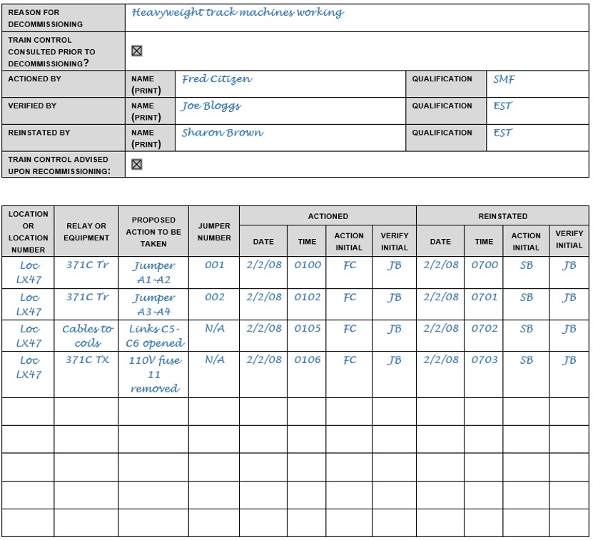
Source: South Australian Public Transport Authority
For occasions where the decommissioning works were able to be planned, the work instruction required the:
- correlation of affected signalling circuits prior to the ITP development (to ensure accuracy of the control circuit drawings)
- preparation and certification of an ITP by a qualified employee that recorded any decommissioning or reinstatement work to be undertaken on the signalling system infrastructure
- independent review to check and certify the ITP prior to issue
- inclusion of the form FO-EM-SP-312 Signal circuit jumpering decommissioning
- TIC or qualified employee responsible for executing the plan to take receipt of the ITP
- decommissioning work to be actioned in accordance with the approved ITP for that project or works
- amendment (if required) to the ITP be recorded on form FO-EM-SP-313 Amendment log. Any amendment was to be independently verified.
For planned works, the work instruction required both the development of an ITP form and the inclusion of form FO-EM-SP-313. The format of the ITP and FO-EM-SP-313 form templates included duplicated information related to the required tasks and records to be kept. The work instruction did not specify how the template forms were to be used together when planning work in advance.
In summary, SAPTA required a qualified employee (rail safety worker) undertaking either unplanned or planned decommissioning work to ensure that:
- another qualified employee was available onsite to verify the correct installation of jumpers
- all documentation associated with temporary decommissioning and jumpering contained complete and accurate information
- the correct operation of those functions was verified [validated] by the qualified employee performing the decommissioning/jumpering
- where signalling functions on adjacent lines were required to remain active (that is, level crossings isolated for the AMPRN line but should operate for ARTC movements), the correct operation of those functions was to be verified by the qualified employee performing the decommissioning/jumpering.
Industry standards for signalling testing and commissioning plans
Overview
The Rail Industry Safety and Standards Board published standards AS-7717-2016 Signal testing and commissioning and AS-7716-2017-Signal testing process. These standards were to provide rail transport operators,[18] such as the RComm, with a common framework to plan and execute the inspection, testing and commissioning activity for new and altered signalling infrastructure on their respective networks.
Signal testing and commissioning
Standard AS-7717-2016 defined the range of inspection and test activities necessary for a rail transport operator to certify the safety of the new or modified signalling system before placing it into service. These included the testing activity required following minor works, such as alterations for the installation and removal of temporary jumper wiring to level crossing control circuits.
Such alterations were to be tested in accordance with the standard considering the type, extent, and risk associated with the particular alterations being made. The nature of the testing and commissioning activities could vary dependent on requirements determined by the accredited rail infrastructure manger,[19] which for the AMPRN and associated GREP works was also the RComm.
The standard stipulated the railway organisation and its management structure together with the planning process and staff competence were each critically important to ensure the railway signalling systems were safe for the operation of trains. The requirements for the planning process included elements such as:
- the production of formal documentation of the required activities and tasks
- the allocation of responsibilities and the personal competencies required to undertake the tasks
- the independence required for people’s involvement among the different parts of the work
- the documentation to be used for the testing and commissioning plans.
The overall objective was the development of a detailed ITP, which documented the processes, work activities, and the controls implemented to achieve the requirements of the standard, using an agreed format.
For the GREP works, the subcontractor, RIC, identified and undertook the development of the ITPs for each level crossing installation. These plans were then forwarded through Acciona and TPD to SAPTA for approval.
Identification of interfaces outside the commissioning boundaries
Standard AS-7717-2016 also required that before inspection and testing activities commenced at sites containing signalling equipment that was in use, the RIM was to be informed of the extent and program of work. Additionally, consideration should also be given to elements outside of the defined boundaries of the commissioning area.
For the GREP level crossing works, the TPD and SAPTA were aware of the extent of the works, and inspection and testing activity through the approval of the GREP Tamping Project Signalling Methodology document and the coordination activities through the TPD onsite project manager.
Interfaces outside the GREP boundaries were managed through the rail-to-rail interface agreement[20] between SAPTA and ARTC. The agreement managed the identified risks to safety that may arise from railway operations carried out by either operator (SAPTA or ARTC) that would affect the other at the shared road-rail interfaces. The agreement included the interface at the Torrens Road level crossing.
The agreement required each operator to provide advance notice to the other, prior to commencing any works likely to materially affect the other operator’s rail network. To address this requirement, Acciona, via TPD, provided ARTC advance notice of the proposed GREP work in the format of a draft train notice.
On 1 December 2020, ARTC published train notice TN2925 advising train crew operating on the ARTC network that tamping works were to be undertaken on the adjacent AMPRN. The notice contained the following information:
- The GREP project will be undertaking tamping and regulating works on the Gawler line between 2.7km to 8.5km (AMPRN km) on both the up and the down track. The works will have no impact on ARTC line and there will be no potential to foul ARTC.
- As part of the works some ballast will be placed inside the corridor North of Ovingham Railway station using the access gate on the ARTC side (at least 3m away from the tracks) and a loader will be intermittently at the stockpile area to load trucks with ballast under TOA [track occupancy authority] between trains.
- The Qualified Rail Safety Worker will be required to take out adjacent line protection TOA [track occupancy authority] ATP [as traffic permits] when operating the Ballast Regulator Side Wing Plough on the Down Main Line.
- The works will have no impact on ARTC Network Services or Operations.
- The Qualified Rail Safety Worker will ensure that communications are made with the Network Controller prior & post work.
The notice indicated that the proposed tamping works would have no impact on the ARTC network nor the potential to obstruct traffic operating on that line.[21] Neither the notice, nor other communication between Acciona, TPD or SAPTA and ARTC identified that temporary alterations would occur to the level crossing control circuity of the shared level crossings in the work area between North Adelaide and Islington, encompassing Torrens Road.
Requirement for independence of persons undertaking testing activity
The planning and implementation of an effective inspection and test regime was a critical element to reduce risk to rail safety associated with undertaking works on vital signalling control equipment. This required the development of ITPs that must include sufficient tasks to support the verification[22] and validation[23] of any new or altered safety‑related signalling system. The standard required:
These verification and validation processes shall be performed at an appropriate level of independence from the construction and implementation process to be verified and validated. The degree and nature of this independence shall be determined by taking into account at least the following factors:
(a) The risk of errors being perpetuated during the verification and validation process due to there being too close an association between the persons performing the verification and validation and those involved in the construction and implementation process.
(b) The risk imposed on the existing system both by the introduction of the system to be verified and validated and by faults or inconsistencies in that system.
The TIC and signal electrician worked together in undertaking both the installation of the temporary jumper wiring and the verification and validation testing of the level crossing control circuitry. Although, in this instance there was close association between the persons performing the work, the standard allowed this arrangement through placing a higher weighting on competence of organisations rather than independence provided:
…where independence cannot be achieved other controls should be considered to assure any additional risk due to a lack of independence is controlled. If it is not possible to achieve independence, then approval shall be given by the RIM [rail infrastructure manger] of the alternative control measures that will be used to control the additional risk due to the lack of available competent independent resources
Other than reviewing the draft ITPs, there was no record of SAPTA assessing the competencies of the rail safety workers undertaking the signalling work. Further, there were no alternative control measures implemented to manage the risk due to the limited availability of other competent independent resources to undertake an independent inspection and test activity.
Signal testing process
The second standard, AS 7716-2017 signal testing process, provided greater detail of the types of testing methods and procedures that may be used when commissioning typical signalling apparatus and systems. Emphasis was again placed on the importance of maintaining independence between the performance of the installation and testing activities. Although the standard described the minimum requirements for undertaking inspection and testing activities, it did not diminish the obligation of the verification, validation and test personnel to decide what should be tested and how it should be tested respectively.
The types of testing methods and procedures were grouped under post‑installation testing, which was to independently verify the new or altered work was built in accordance with the design documentation (in this case the circuit diagram) and secondly, the function testing and validation phase, which proved the new or altered work performed as designed.
Installation testing verified the system was built in accordance with the design required testing include the following:
- detailed circuit testing
- cables testing
- apparatus testing.
System testing and validation included the following:
- [design] function testing
- testing to control tables[24]
- aspect sequence[25] testing
- [design] principles testing.[26]
For the GREP level crossing works, RIC provided the TIC with a pre-approved suite of ITPs to specify the tasks they were required to perform to install/remove temporary jumpers, and for the testing and validation of the altered control circuit to ensure the level crossing warning equipment functioned as the design intended.
Torrens Road inspection and test plan
Overview
The Torrens Road ITP document specified the processes approved by the RIM that RIC (TIC and signal electrician) would undertake for the planned temporary decommissioning of critical signalling system infrastructure (see Appendix C – Torrens Road inspection and test plan). The ITP was divided into 3 sections that contained the:
- details for the document version control, plan approval signatures and allocated responsibilities to undertake defined roles
- verification tasks to ensure the sign-off acceptance for the allocated responsibilities and confirmation of safe working and IBA arrangements
- master test certificate tasks to confirm safe working arrangements and the specifications for the sequence of installation and inspection and test activities the TIC was required to coordinate and sign off as completed.
Plan implementation
The verification section of the Torrens Road ITP document required the TIC to ensure documents were attached and details of allocated responsibility completed. The section also required the TIC to confirm that safe working procedures were in place and to ‘take out’ an IBA before commencing work. The latter, in compliance with SAPTA rules, would include direct communication between the TIC and operations controller prior to the commencement of any work to alter signalling infrastructure.
On this occasion, the worksite was under the control of a PPO and there was no direct contact between the TIC and operations controller. The TIC and PPO, however, did not follow either the signalling methodology or IBA procedures, which required the completion of an IBA form prior to the commencement of work. The TIC and PPO instead agreed verbally to complete the jumper installation, before meeting later that morning to complete the IBA. Although the TIC had undertaken several actions to address the various safe working, IBA, and other tasks in the verification section, those tasks were not signed off in the plan document as complete.
Temporary jumper wiring installation
The plan detailed the series of tasks to be coordinated by the TIC that related to the temporary jumper installation (Figure 9).
Figure 9: Master test certificate, section 2 page 1 of the Torrens Road inspection and test plan
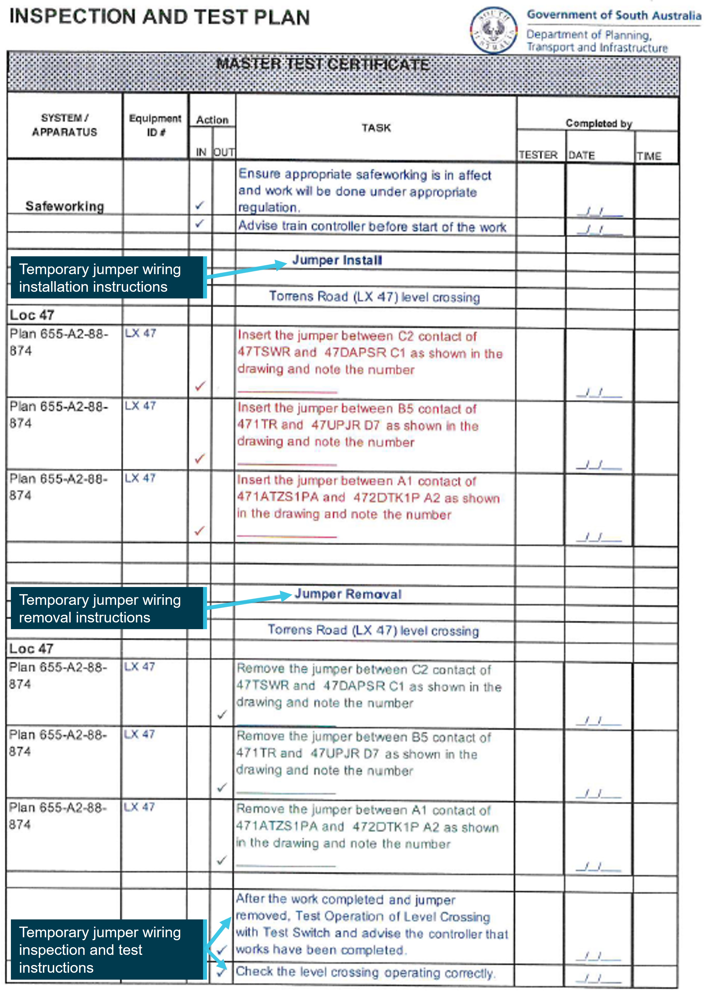
Note: Extract of the SAPTA‑approved ITP specifying the required tasks and records to evidence completion of that task. Source: South Australian Passenger Transport Authority, annotated by the ATSB
The ‘jumper install’ section of the plan contained a description of where to terminate each jumper wire and an associated field for the TIC to record the identification number of the jumper together with details of the date, time, and the tester who certified that task was completed. Although the tasks to install the 3 jumpers in the level crossing control circuit were actioned by the TIC, no entry was recorded in the plan to specify the jumper identification number or to certify that task was completed.
The task descriptions in the plan document for the installation of the jumpers (highlighted in red font) reflected the circuit diagram (marked up in red). The circuit diagram showed 3 jumpers positioned in the level crossing control circuit to bypass functions that could be affected by the track tamping works (Figure 10).
Temporary jumper wire ‘A’ bypassed the control function that incorporated the up-direction AMPRN track circuits to the level crossing that were to be disconnected to facilitate the track work. The jumper wires ‘B’ and ‘C’ bypassed control functions associated with the automatic operation of the level crossing warning equipment when configured for single line bi-directional working.
The TIC stated that, on reflection, only one temporary jumper wire was required. The other 2 jumpers (marked ‘B’ and ‘C’ in Figure 10) were superfluous[27] as they bypassed the single line working function, which was not planned to be in use on 7 December 2020. The single line working function would only be used where single line bi-directional working was instigated under an alternative method of safe working arrangement. This was not the case on 7 December 2020.
Figure 10: Extract of the SAPTA‑approved Torrens Road inspection and test plan showing approved temporary wiring configuration
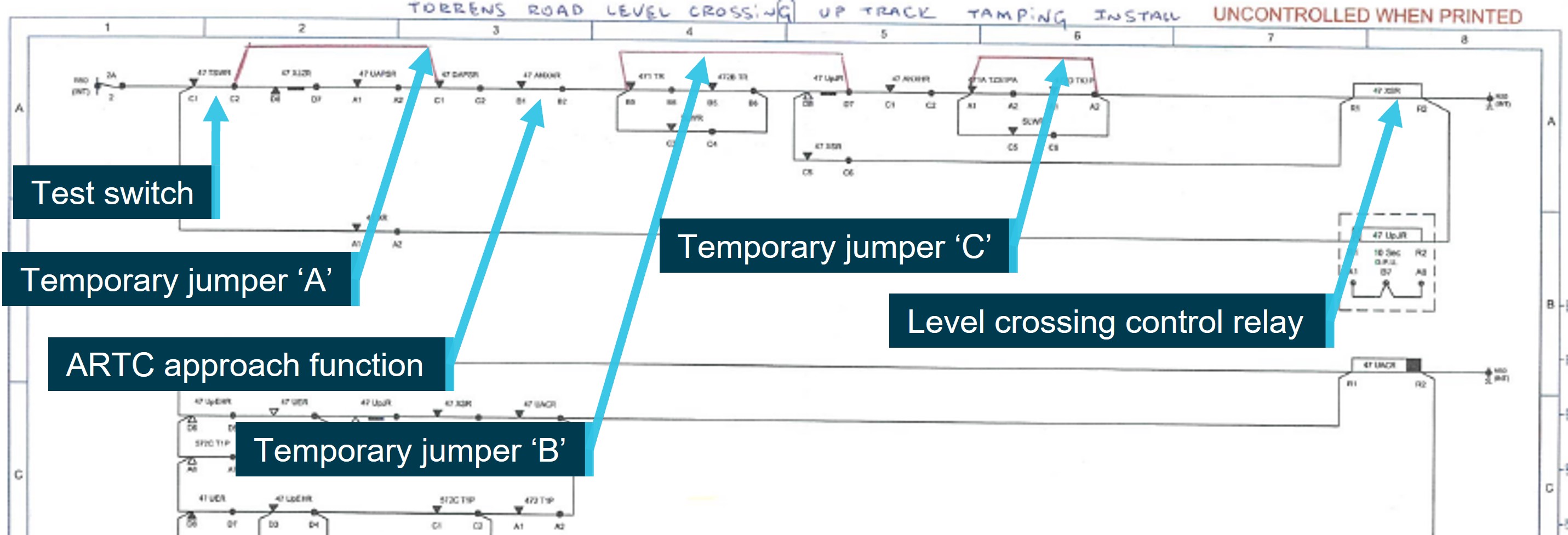
Note: Extract of circuit diagram showing the SAPTA‑approved location for the 3 temporary jumper wires. Source: South Australian Passenger Transport Authority, annotated by the ATSB.
The TIC used the circuit diagram when calling instructions to the signal electrician on where to connect the ends of each jumper to the respective relay bases. The signal electrician did not have a copy of the diagram.
The relay base contained a matrix of termination points arranged in columns marked ‘A’ to ‘D’. The terminations in the ‘D’ column were located on the right side of the relay base. Each column then contained 8 rows of terminations. The base was embossed with markings that corresponded to the relative position of the termination in the matrix, for example ‘D1’ to ‘D8’. Each could connect up to a maximum of 2 wires. In addition to the embossed markings, each wire connected to a respective termination point that was fitted with a numbered colour‑coded sleeve. The colour of the sleeve was dependent on the column, for example, wires in the ‘D’ row were yellow. The sleeves were not fixed to the wire and could be moved along the wire to enable the rail safety worker to view the identification number of the wire if required.
During the installation of the temporary jumper (RIC01*11) between the function 47 1TR - B5 and 47 UpJR ‑ D7 (marked ‘Temporary jumper ‘B’’ in Figure 10), the probe from one end of the jumper was inadvertently placed into 47 UpJR - D6. This was located directly above the intended termination point (47 UpJR ‑ D7) detailed in the ITP and positioned on the bottom row of the relays in the equipment rack (Figure 11).
Figure 11: Rear of Torrens Road location case showing 47 UpJR control relay
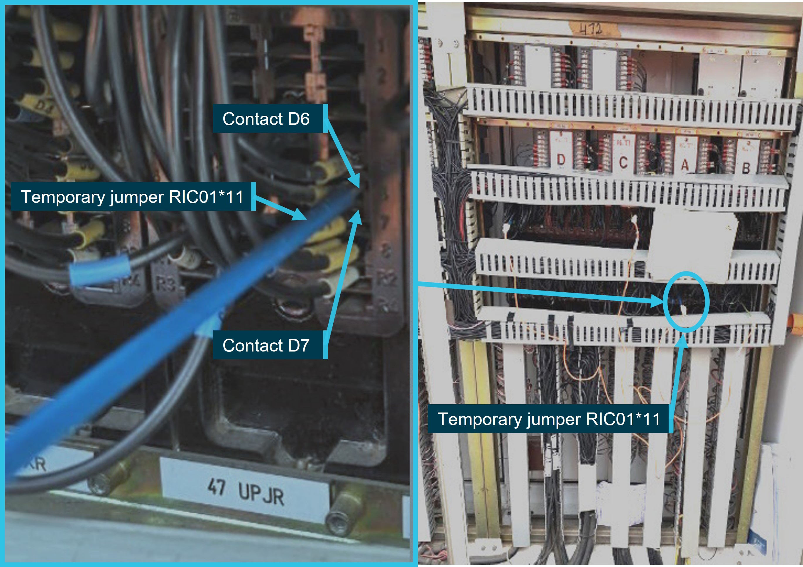
Source: South Australian Passenger Transport Authority, annotated by the ATSB
One end of another jumper was installed to a termination (47 XSR R1) other than that identified in the approved circuit diagram. This was intentional and made under the instruction of the TIC. This amendment was undertaken as access to the nominated termination was impeded due to its physical location in the equipment rack and congestion from the existing wiring. This amendment did not change the intended functionality of the jumper or level crossing control circuit. The TIC subsequently illustrated the amended wiring on the circuit diagram. However, no corresponding amendment record was completed in the plan document to ensure correlation between the plan and circuit diagram.
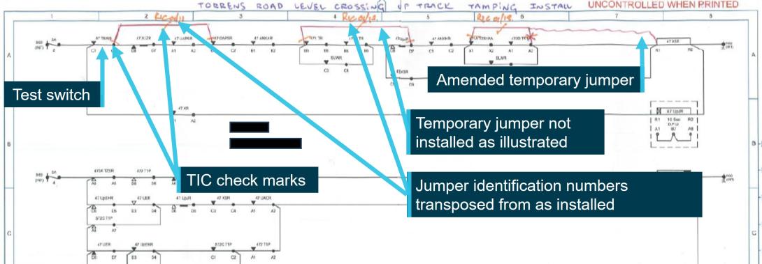
The unintentional installation of a jumper probe into the 47 UpJR - D6 terminal and intentional termination of a jumper probe into the 47 XSR R1 termination meant the jumper wiring was configured as illustrated in Figure 12. This was inconsistent with the description in the approved plan document and detail shown on the amended circuit diagram.
Figure 12: Extract of the Torrens Road level crossing control circuit showing temporary jumper wires in the ‘as installed’ configuration
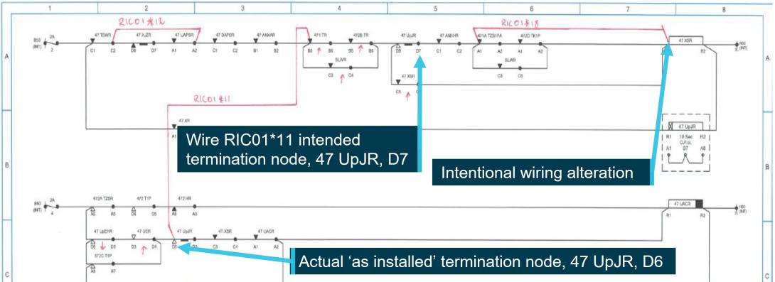
Note: Configuration of the temporary jumper wiring recorded by SAPTA during the post-incident onsite investigation. Source: South Australian Department for Infrastructure and Transport, annotated by the ATSB
Temporary jumper wiring testing
Verification
Following the temporary jumper install, there were no post‑installation testing tasks included in the ITP to specify the tests that the TIC was to coordinate to ensure correctness. Such tests were typically required to ensure the ‘as installed’ wiring conformed to the circuit diagram and that the required control functions would still operate the level crossing warning equipment as designed. In this case, the operation of the level crossing warning equipment for trains approaching on the ARTC network.
In the absence of any instruction from SAPTA to specify the testing or methodology required for recording test results, the TIC used their typical method for recording verification testing and marked up the circuit diagram with details to record the installation of each jumper together with its identification number (Figure 13).
Figure 13: Extract from the Torrens Road inspection and test plan marked up with testing annotations and amended jumper wiring configuration
Note: Extract of the circuit diagram showing the location of the temporary jumper wiring and TIC testing notations as completed on 7 November 2020. Signatures removed to de-identify the involved parties. Source: South Australian Passenger Transport Authority, annotated by the ATSB
The TIC recorded each test activity using a system of symbols to signify the installation and verification of the jumper wire in accordance with the approved circuit diagram. The markings indicated the TIC had certified the completion of a wire count[28] and continuity test[29] for each of the installed jumpers. The TIC also used an asterisk to denote that one end of a jumper was no longer connected at the terminal originally approved.
When marking up the circuit diagram, the TIC did not undertake an independent visual inspection to verify the correct installation of the jumper wiring. The TIC acknowledged that they should have undertaken an independent visual check, but instead had relied on the information provided by the signal electrician, due to their significant experience in undertaking work on signalling systems. The TIC stated that there were limited resources in the signal team and no other member had the qualification required to undertake independent testing. The TIC stated that there was therefore a tendency not to check the work undertaken as rigorously as would be the case for a team member with less experience.
The methodology used by the TIC to verify the ‘as installed’ wiring against the control circuit diagram did not detect the error made in the termination of the jumper wire RIC01*11 into the 47 UpJR - D6 terminal (instead of 47 UpJR – D7) or the transposition of the unique identification numbers for 2 of the jumper wires.
The TIC stated that the ITP (plan document) was not identified as a commissioning work instruction and, in their mind, it appeared only as a reference document to ensure the circuit diagrams were attached, the PPO was informed and the IBA had been completed. The TIC also noted the level of documentation provided to support their work was minimal in comparison to their experience when undertaking similar tasks with other rail organisations. The TIC stated the information in the ITP document basically reflected information related to the jumper installation and removal that was contained in the circuit diagrams. It did not appear to them as a typical work instruction forming part of a commissioning plan.
Validation
Following the completion of the verification tests, the TIC operated the level crossing test switch (Figure 13) located in an enclosure on the AMPRN location case to validate the correct operation of the level crossing circuit (and warning equipment). The level crossing warning equipment operated as the TIC expected. The TIC recalled that there was no mention in the ITP of testing the functionality of the ARTC level crossing, and that the only validation test specified was the operation of the test switch, following the removal of the temporary jumpers.
The test of the ARTC approach function required either the operation of the test switch on the ARTC signalling system control box or the interruption by other means of the ARTC approach control function relayed to the AMPRN signalling system. The TIC stated that, in hindsight, when testing the functionality of the level crossing warning equipment, the ARTC test switch should have also been operated to validate the correct operation of that function.
Although the TIC undertook tests to validate the correct operation of the level crossing equipment, the tests did not identify the wiring error. In this instance, another relay function in the control circuit needed to change state for the error to become apparent by the operation of the ARTC test switch or approach control function.
There was no record on the circuit diagram or plan document to indicate any testing of a control function had occurred (including by the operation of the test switch). The TIC signed off the ITP circuit diagram to certify the temporary jumper installation was completed, and the level crossing warning equipment functioned as expected.
In preparation for the track tamping work to commence, the signal team disconnected connections for the 572C track that caused a 572C T1P relay to de-energise. The change in state of this relay closed contacts A7 and A8. An alternative connection from the control circuit power supply was applied to the 47 XSR function via the incorrectly installed jumper wire RIC01*11 (Figure 14). The false feed subsequently maintained the 47 XSR function in an energised state (level crossing warning equipment inactive), regardless of the configuration of another AMPRN or ARTC control input in the circuit. The level crossing warning equipment would now not operate for train 1MP9 approaching Torrens Road on the ARTC network, or any other AMPRN or ARTC train approaching the level crossing.
Figure 14: Extract of the Torrens Road level crossing control circuit showing the path of false feed
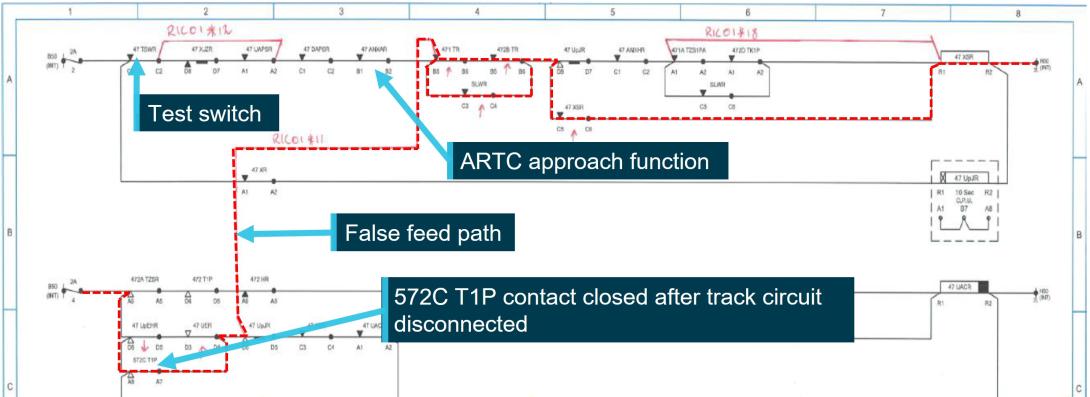
Note: Red dashed line shows the path of the false feed applied to the Torrens Road level crossing control relay, after 572C T1P relay was de-energised. Source: South Australian Department for Infrastructure and Transport, annotated by the ATSB
Removal
The ITP document also specified tasks related to the ‘jumper removal’, which was to occur following the completion of the track work for that day. The work at Torrens Road had not progressed to a stage where these tasks needed to be actioned.
Associated with the tasks for jumper removal, additional tasks were included for the TIC to action. This included a test for the operation of the level crossing warning equipment with the test switch, to ensure the level crossing operated correctly, before advising the operations controller (in this case PPO) the works were complete.
The installation or removal of the jumper wiring did not affect the test switch. Operating the test switch only confirmed that the warning equipment would function using the switch. It did not confirm that a train approaching the Torrens Road level crossing on either the AMPRN or ARTC network would activate the warning equipment in the same way.
Summary
In summary, the extent of the testing requirements specified in the Torrens Road ITP following the jumper installation work were consistent with those developed for each of the other level crossings affected by the GREP track works that day (Bedford Road and Pym Street). None of the approved ITPs specified a requirement to:
- verify the temporary jumpers were per the plan description and circuit diagram
- validate the level crossing warning equipment would operate as intended with the temporary jumper wiring, particularly the continued operation of the level crossing warning equipment for trains approaching on the ARTC network.
Additionally, after completing the installation and testing phase, the scope of work for the signalling team on the day included the removal and reinstatement of several track circuit connections that were associated with the AMPRN up approach to the Torrens Road and other level crossings. In the absence of the use of form FO-EM-SP-312Signal circuit jumpering decommissioning, there was no provision made in the ITP documentation for the TIC to record the signal team’s actions associated with the removal, reinstatement or testing of the affected track circuit connections. Although there was no requirement in the ITP documentation, the GREP signalling methodology document specified the track maintenance record card for the affected track circuit must be completed as the equipment was tested and certified. These documents were distributed at various trackside location cases and were separate from the ITP document package developed to record the specialised rail safety work undertaken by the signal team for the GREP.
SAPTA post-incident onsite investigation
An onsite examination by SAPTA found:
- The ITP used by RIC was not located in the location case as required by SAPTA procedures.
- The ITP document, when provided, was not completed.
- A comparison of the temporary wiring modifications against the ITP circuit diagrams identified the 3 temporary jumper wires were not installed in accordance with the details recorded in the approved circuit diagram.
- One end of a temporary jumper wire was terminated to the wrong point in the circuit.
- The incorrectly terminated temporary jumper wire subsequently provided a circuit, which falsely energised a relay that would have otherwise been de-energised during correct operation of the level crossing. This was determined as the reason for the level crossing warning equipment not activating for the approach of 1MP9 on the adjacent ARTC network.
Safety analysis
Introduction
On 7 December 2020, Specialised Container Transport train 1MP9 was travelling on the Australian Rail Track Corporation (ARTC) network through Adelaide in South Australia. As the train approached the Torrens Road level crossing, the driver saw that road traffic was still passing over the crossing, and that the level crossing warning equipment had not operated for the approach of the train. The driver initiated an emergency brake application before sounding the locomotive horn to alert any road traffic of the train’s approach. Shortly after, the train traversed the level crossing and continued a further 260 m before stopping.
This analysis will discuss the pre-planned tasks the signal team was required to undertake at short notice. It will then examine the limitations in the methodology adopted by members of the signal team during the installation and subsequent testing to certify the temporary wiring alterations and to ensure the level crossing warning equipment operated correctly.
Further, limitations in the development and approval processes for the inspection and test plans, and the associated procedures used to manage the specialised safety‑critical work to alter signalling infrastructure, such as the control circuits for level crossings, will also be considered.
Work plan change
On the morning of the incident, the signal team recommenced the planned work activity in support of the tamping works as was agreed during the pre-work briefing for that day. The signal team was familiar with the work as it was repeating an activity to alter the Pym Street and Belford Avenue level crossing control circuits, which it had successfully undertaken over the previous few days.
The control circuits for these 2 crossings were co-located in the Islington relay room situated at the northern end of the track worksite. This meant the tester in charge (TIC) and signal electrician could sequentially complete the tasks described in the respective inspection and test plans (ITPs) before relocating to the track area to commence the work associated with the removal of electrical connections to the rails. On completion of the track tamping works, the signal team would then reinstate and test the equipment before placing it back into service and signing off. The signal team was typically working 11.5 to 12 hour shifts each day to complete this scope of work involving the 2 level crossings and their associated track circuits.
The TIC had felt the signal team was under constant work pressure from the tamping workgroup to complete its work and that there was not an understanding of the time needed to undertake the signal works both before and after the track works were completed. The signal electrician reflected similar observations to that of the TIC and added that their workload at the commencement of that day was reasonable, but this had increased due to repair of damage to electrical connections caused by the tamping machine earlier that day.
However, the decision to add the third level crossing (at Torrens Road) at short notice and additional track circuit connections within the 12-hour workday requirement and allocated track possession timeframe placed further demands on the signal team. In addition, these tasks were not located near the Islington relay room like the previous works and were instead located toward the opposite end of the worksite. The TIC and signal electrician reported that they were cognisant that this work needed to be progressed as expeditiously as possible, to not further delay the track machine workgroup schedule in continuing its work toward Torrens Road, which had experienced previous delays. To save time, the TIC modified their usual approach to the infrastructure booking advice process (as part of the signalling method procedure), by making arrangements with the possession protection officer by telephone rather than meeting together to complete the advice form. This was likely to reduce the need to travel within the worksite before commencing work to modify the level crossing circuitry.
Work pressure is defined as degree to which employees feel under pressure to complete work, amount of time to plan and carry out work, and balance of workload (Glendon and Stanton, 2000). Employees who perceive that they are under pressure to increase production may deviate from safety rules that impede their progress, or perform tasks with less care, increasing the likelihood of errors. There is evidence for a link between work demands and accident involvement, where the higher the perception of work demands, the more accidents that occur (Clarke, 2006). Time pressure has also been found to degrade performance, such as task or load shedding, and a trading of accuracy for speed (Staal, 2004).
Together, this indicated that the signal team was experiencing actual or perceived work pressure with the addition of the Torrens Road level crossing, which influenced the deviation from adhering to the requirements outlined in the standard signalling methodology procedure.
|
Contributing factor A late change to the planned scope of track tamping work on the day of the incident placed additional work demand with short notice on the signal team to implement the Torrens Road inspection and test plan. |
Inspection and test plan – wiring
The ITP reviewed and approved by South Australian Public Transport Authority (SAPTA) required the TIC and signal electrician to install 3 temporary jumper wires to isolate the Adelaide metropolitan passenger rail network (AMPRN) up approach at the Torrens Road level crossing. Post-incident, both the TIC and signal electrician stated the installation could have been simpler, as the circuit alterations to facilitate the track work required the installation of only one of the jumpers, instead of 3.
During the installation of the jumpers, one of the superfluous jumpers was inadvertently installed to an incorrect point in the control circuit. Further, the installation of the second jumper required the TIC to undertake an amendment to the termination point to allow for simpler installation, increasing the complexity of the task. These 2 conditions could have been averted by the identification and removal of unnecessary jumpers from the Torrens Road ITP during the various stages of the review and approval process.
SAPTA required Acciona to submit the draft ITPs for their final review and approval prior to the commencement of work on the AMPRN. While the SAPTA review identified various drafting errors in some of the ITPs (excluding Torrens Road), there was no comment from SAPTA in relation to the inclusion of superfluous wiring. The inclusion of superfluous jumpers was common across the approved ITPs for the level crossings that were altered by the signal team during the track work earlier on that day and over the preceding days.
On 7 December 2020, each of the Bedford Avenue, Pym Street and Torrens Road ITPs required the signal team to install temporary wiring that bridged the single line working switches. The inclusion of superfluous wiring in the approved ITPs placed an unnecessary task demand on the signal electrician and TIC when performing work associated with the modification and testing of safety‑critical signalling infrastructure. The approved inspection and test plan for the Torrens Road level crossing control circuit included 2 superfluous temporary jumper wires. The inclusion of superfluous wiring both increased complexity of the task and placed unnecessary work demand on the signal electrician and tester in charge to implement the plan.
|
Contributing factor The inspection and test plan for the Torrens Road level crossing control circuit included 2 superfluous temporary jumper wires. The inclusion of superfluous wiring both increased complexity of the task and placed unnecessary work demand on the signal electrician and tester in charge to implement the plan. |
Temporary jumper wiring installation
After accessing the Torrens Road location case, the TIC and signal electrician positioned themselves on opposite sides of the equipment rack. During the installation, the TIC likely called out to the signal electrician to install the probe of a jumper into terminal D7 of the 47 UpJR.
The signal electrician did not have a copy of the circuit diagram to reference or cross‑check during the installation process for the jumpers and therefore relied on recalling the verbal instructions provided by the TIC. The signal electrician could however seek clarification from the TIC if they were unsure of the instruction or connection point that was provided. The 47 UpJR control relay was located in the bottom row of the relays installed in the equipment rack (Figure 11).
Together, it was possible that the increased time pressure, method for the installation of the temporary jumper wiring, and familiarity of the task from preceding work all combined to influence the unintentional installation of 47 UpJR into node D6, which was immediately above D7. This meant the jumper installed was not consistent with the approved ITP document and control circuit drawing and introduced a latent condition for the incorrect operation of the level crossing warning equipment.
|
Contributing factor The signal electrician inadvertently installed one end of a superfluous temporary jumper wire to an incorrect terminal within the control circuit of the Torrens Road level crossing warning equipment. The installation error meant the jumper was not consistent with the approved control circuit. |
Verification of signalling works
The Gawler rail electrification project (GREP) Tamping project signalling methodology procedure for planned work required the TIC to undertake and record their work in accordance with the content of the SAPTA‑approved ITP. However, none of the ITPs or other documentation developed for the GREP level crossing work specified a requirement for the TIC to undertake and record an independent verification of the correct installation of temporary jumper wiring. Although the verification task was not specified in the ITPs, the TIC (and signal electrician) had previous experience in commissioning signal system alterations and were cognisant of the need to undertake a verification inspection for the correct installation of the jumpers.
The independent verification of a control circuit alteration could be satisfied by a variety of arrangements dependent on the availability of suitably qualified resources. At a minimum level, independent verification would require the wiring installation work undertaken by one rail safety worker to be verified (inspected and certified) as correct by another rail safety worker, who held an equivalent or higher competency and was not directly involved with the initial wiring installation work.
For the work at Torrens Road (and other level crossing installations affected by the GREP work) the qualified resources of the signal team comprised 2 rail safety workers, the signal electrician and TIC. To satisfy the minimum level of independence would typically require the signal electrician to have access to a circuit diagram (construction copy) to carry out and record the installation or removal of each jumper independently from involvement of the TIC. On completion, the TIC, referencing the ITP documentation would then verify and certify the correct installation of the jumpers independently from involvement of the signal electrician.
The methodology adopted by the TIC during the installation of the wiring, where they retained the circuit diagram and called the termination node to the signal electrician before marking the respective wire as installed, essentially combined the installation and verification tasks into a single step. Consequently, there was no independent verification of the installed wiring. This resulted in the wiring error not being detected and remaining in the circuit as a latent condition.
The approach adopted by the signal team was likely influenced by the close working association it had established through the repeated implementation of the ITPs to alter the level crossing control circuits, as well as the completion of other tasks undertaken to facilitate the tack tamping works. The signal electrician and TIC repeatedly completed these specialised works successfully under time pressure over a number of preceding days and likely developed a level of trust in each other’s ability to competently complete the alteration work without error or omission.
The Rail Industry Safety and Standards Board standard required the planning and implementation of an effective inspection and test regime to reduce risk to rail safety. To achieve this, the standard required the verification and validation process that forms the inspection and test regime to be undertaken with independence between the construction (installation) and testing (commissioning) process. The standard, however, allowed for situations where the independence could not be achieved. In that instance, other controls should be considered and approved by the rail infrastructure manager to control the additional risk.
|
Contributing factor The methodology adopted by the signal team when implementing the Torrens Road inspection and test plan did not ensure independence between the installation and verification tasks. This resulted in the wiring error not being corrected and remaining in the Torrens Road control circuit, potentially affecting the correct operation of the level crossing warning equipment. |
Tamping preparation works
After completion of the temporary wiring alterations, the TIC and signal electrician concluded the jumpers were installed correctly and that the warning equipment would continue to function as intended. The signal team then left the Torrens Road level crossing. Following approval from the TIC, the signal electrician and trades assistants then commenced work to remove the required track circuit electrical connections from the rails so the track work could continue.
The removal of the track connections should have had no effect on the correct operation of the Torrens Road level crossing warning equipment. That is, the altered level crossing control circuit would not operate the warning equipment due to the removal of the track circuit connections on the AMPRN, but would still operate either by the use of the test switch or for the passage of a train on the adjacent ARTC network.
In this instance, due to the earlier undetected error in the installation of one of the jumpers, the removal of the track circuit connections for the 572C track resulted in a change of state of the 572C T1P function in the level crossing control circuit. This condition, together with the wiring error, resulted in a wiring connection that provided alternative connection from the control circuit power supply to the 47 XSR control relay. This now prevented the correct operation of the level crossing control circuit and warning equipment.
This condition was not present at the time the TIC and signal electrician tested (validated) the correct operation of the level crossing warning equipment by using the level crossing test switch. Therefore, the TIC and signal electrician, having left the Torrens Road level crossing after completing the installation and test tasks, would not have been aware the level crossing would now not operate either by the selection of the test switch or the passage of a train on the adjacent ARTC network.
As the alternative connection condition was not present during the time the TIC undertook the validation testing, the detection and correction of the wiring error was therefore solely reliant on the effectiveness of the verification testing that was undertaken following the installation of the temporary jumper wiring.
|
Other factor that increased risk The inspection and test methodology used by the signal team to validate the operation of the level crossing warning equipment via the operation of the Adelaide Metropolitan Passenger Rail Network level crossing test switch did not prove the Australian Rail Track Corporation level crossing control function would operate the warning equipment. |
Inspection and test plan – testing
For the GREP level crossing works, Rail Industry Constructions (RIC) developed a package of ITP documents through copying the format of ITPs that RIC had used for projects previously undertaken on the AMPRN signalling system. Other than stipulating the ITPs were to be submitted for approval, SAPTA provided no specification or guidance to define the minimum content that RIC was to follow during the drafting and later application of the ITP documents.
The ITPs subsequently developed by RIC reflected the content of various pre-populated fields that described generalised tasks to confirm details of plan references, responsibilities and authorities, safe working, and communication arrangements. A sequence of tasks was added to the master test certificate section that reflected information contained in the circuit diagrams for the temporary jumper wiring installation or removal tasks. RIC only specified a test of the signalling system integrity (by operation of the test switch) would occur after the removal of the jumpers.
The RISSB signalling testing process standards described the types of testing and methods for testing typical signalling apparatus and systems that form part of a signalling system. A key objective of a test activity was to provide assurance the new or altered signalling system conformed with defined functional requirements, such as maintaining the operation of level crossing warning equipment for trains operating on the ARTC network. The ITP provided a template to document the equipment to be altered, and the planned sequence of tasks including an effective auditable process for the verification and validation of the safety integrity of the altered signalling system to meet the defined functional requirements.
The ITPs subsequently developed by RIC for the GREP level crossing control circuit alterations were tailored toward a checklist addressing administrative tasks. Therefore, the ITPs did not include sufficient detail to form an effective and auditable test procedure to verify and validate the safety integrity of level crossing control circuits following the installation of the temporary jumper wiring.
|
Other factor that increased risk Rail Industry Constructions developed a package of inspection and test plans that did not include effective and auditable test procedures to verify and validate the safety integrity of level crossing control circuits following the installation of the temporary jumper wiring. |
Inspection and test plan checking/approval process – testing
On 25 September 2020, RIC representatives endorsed the draft ITPs for each level crossing location that would be affected by the GREP track tamping work. The ITPs were subsequently submitted to SAPTA for review and approval to verify that the specifications contained in the ITPs were appropriate for application on the AMPRN.
The review identified errors in several of the ITPs, which SAPTA returned to RIC for correction. The errors related to an inconsistency between the task description in the plan document and the related marked up circuit diagram. SAPTA identified no errors in the positioning of the various temporary jumper wires as marked-up on the control circuit diagrams.
In reviewing the proposed wiring alterations, SAPTA did not provide any feedback to RIC on the inclusion of the superfluous jumpers to inhibit control functions that were not necessary to achieve the objective. That is, to prevent the unnecessary operation of the level crossing warning equipment during the track work. The SAPTA acceptance of the extra wiring alterations both unnecessarily increased the workload on the signal team and introduced a potential risk to safety that may arise from an undetected error during the installation works.
A SAPTA‑qualified employee undertaking similar works must undertake the planned temporary decommissioning of signalling system infrastructure in accordance with the SAPTA work instruction Signalling system temporary decommissioning and jumpering. The instruction required the qualified employee implement a pre-approved ITP for the works. The work instruction emphasised to the SAPTA‑qualified employee their responsibility to ensure there was independence in the verification testing of the installed wiring. Additionally, where there were adjacent rail lines, the employee was to validate the correct operation of the signalling functions on that line to ensure they remained active following the completion of the alteration work. In this instance, the level crossing control functions were isolated for AMPRN but were to continue operating for trains on the adjacent ARTC network.
A key objective of the SAPTA review and approval process was to ensure the ITP procedures developed by subcontractors (RIC) for implementation by the signal team on the AMPRN were, at a minimum, consistent with SAPTA procedures and/or included methods that provided improved risk control. The SAPTA review did not identify the omission of specific inspection and test tasks to ensure there was independent verification that the jumpering was correctly installed, and that the ARTC control function to operate the level crossing warning equipment for a train approaching on the ARTC network was validated. Consequently, the effectiveness of the tests to control risk and assure the safety integrity of the rail infrastructure for trains operating on the ARTC network relied solely on the methodology adopted by a subcontracted signal team on the day.
|
Other factor that increased risk The South Australian Passenger Transport Authority approved a package of inspection and test plan procedures that did not specify any requirement for testing to verify and validate the safety integrity of the altered level crossing control circuits. The effectiveness of inspection and test plan process to control risk and provide assurance the signalling system functioned safety for trains operating on the Australian Rail Track Corporation network relied solely on the methodology adopted by the subcontracted signal team. (Safety issue) |
Validation of signalling works
The Rail Industry Safety and Standards Board standard for signal testing processes required the TIC to complete tests to verify the installed wiring alteration conformed to the control circuit diagrams and then confirm that the requirements of the alteration were fulfilled. In this instance, the requirements, although not specified in the ITP, were the correct operation of the level crossing warning equipment via the manual operation of the AMPRN test switch and the automatic operation for a train approaching the Torrens Road level crossing on the ARTC network.
The TIC stated that, on completion of the jumper installation, they did validate the correct operation of the level crossing warning equipment via the manual operation of the AMPRN test switch. Although the level crossing warning equipment did function as the TIC expected, this was not an effective inspection and test method to prove the ARTC approach control function would operate the warning equipment. While the test proved the AMPRN test switch function operated the level crossing warning equipment it did not prove the ARTC control function would similarly operate the warning equipment.
To prove the ARTC control function required the TIC to manually select the ARTC test switch (located on a separate ARTC location case) or interrupt by other means the ARTC approach control function relayed from the ARTC to the AMPRN signalling system. The validation testing conducted in this manner by the TIC would, in this instance, not identify the incorrect installation of the jumper unless a further condition related to the 572C T1P function was present at the time the validation testing occurred.
|
Other finding The later disconnection of electrical connections to the rails on the Adelaide metropolitan passenger rail network caused a false feed to the level crossing control relay via the incorrectly installed temporary jumper wire. This false feed prevented the correct operation of the level crossing warning equipment for a train approaching on the Australian Rail Track Corporation network. |
Findings
|
ATSB investigation report findings focus on safety factors (that is, events and conditions that increase risk). Safety factors include ‘contributing factors’ and ‘other factors that increased risk’ (that is, factors that did not meet the definition of a contributing factor for this occurrence but were still considered important to include in the report for the purpose of increasing awareness and enhancing safety). In addition ‘other findings’ may be included to provide important information about topics other than safety factors. Safety issues are highlighted in bold to emphasise their importance. A safety issue is a safety factor that (a) can reasonably be regarded as having the potential to adversely affect the safety of future operations, and (b) is a characteristic of an organisation or a system, rather than a characteristic of a specific individual, or characteristic of an operating environment at a specific point in time. These findings should not be read as apportioning blame or liability to any particular organisation or individual. |
From the evidence available, the following findings are made with respect to the level crossing irregularity involving freight train 1MP9 that occurred on 7 December 2020 at Torrens Road level crossing, Ovingham, South Australia.
Contributing factors
- A late change to the planned scope of track tamping work on the day of the incident placed additional work demand with short notice on the signal team to implement the Torrens Road inspection and test plan.
- The inspection and test plan for the Torrens Road level crossing control circuit included 2 superfluous temporary jumper wires. The inclusion of superfluous wiring both increased complexity of the task and placed unnecessary work demand on the signal electrician and tester in charge to implement the plan.
- The signal electrician inadvertently installed one end of a superfluous temporary jumper wire to an incorrect terminal within the control circuit of the Torrens Road level crossing warning equipment. The installation error meant the jumper was not consistent with the approved control circuit.
- The methodology adopted by the signal team when implementing the Torrens Road inspection and test plan did not ensure independence between the installation and verification tasks. This resulted in the wiring error not being corrected and remaining in the Torrens Road control circuit, potentially affecting the correct operation of the level crossing warning equipment.
Other factors that increased risk
- The inspection and test methodology used by the signal team to validate the operation of the level crossing warning equipment via the operation of the Adelaide Metropolitan Passenger Rail Network level crossing test switch did not prove the Australian Rail Track Corporation level crossing control function would operate the warning equipment.
- Rail Industry Constructions developed a package of inspection and test plans that did not include effective and auditable test procedures to verify and validate the safety integrity of level crossing control circuits following the installation of the temporary jumper wiring.
- The South Australian Passenger Transport Authority approved a package of inspection and test plan procedures that did not specify any requirement for testing to verify and validate the safety integrity of the altered level crossing control circuits. The effectiveness of inspection and test plan process to control risk and provide assurance the signalling system functioned safety for trains operating on the Australian Rail Track Corporation network relied solely on the methodology adopted by the subcontracted signal team. (Safety issue)
Other findings
- The later disconnection of electrical connections to the rails on the Adelaide metropolitan passenger rail network caused a false feed to the level crossing control relay via the incorrectly installed temporary jumper wire. This false feed prevented the correct operation of the level crossing warning equipment for a train approaching on the Australian Rail Track Corporation network.
Safety issues and actions
|
Central to the ATSB’s investigation of transport safety matters is the early identification of safety issues. The ATSB expects relevant organisations will address all safety issues an investigation identifies. Depending on the level of risk of a safety issue, the extent of corrective action taken by the relevant organisation(s), or the desirability of directing a broad safety message to the rail industry, the ATSB may issue a formal safety recommendation or safety advisory notice as part of the final report. All of the directly involved parties were provided with a draft report and invited to provide submissions. As part of that process, each organisation was asked to communicate what safety actions, if any, they had carried out or were planning to carry out in relation to each safety issue relevant to their organisation. Descriptions of each safety issue, and any associated safety recommendations, are detailed below. Click the link to read the full safety issue description, including the issue status and any safety action/s taken. Safety issues and actions are updated on this website when safety issue owners provide further information concerning the implementation of safety action. |
Inspection and test plan checking/approval process - testing
Safety issue number: RO-2020-021-SI-03
Safety issue description: The South Australian Passenger Transport Authority approved a package of inspection and test plan procedures that did not specify any requirement for tests to verify and validate the safety integrity of the altered level crossing control circuits. The effectiveness of inspection and test plan procedure to control risk and provide assurance the signalling system functioned safety for trains operating on the ARTC network relied solely on the methodology adopted by the subcontracted signal team on the day.
Safety action not associated with an identified safety issue
| Whether or not the ATSB identifies safety issues in the course of an investigation, relevant organisations may proactively initiate safety action in order to reduce their safety risk. The ATSB has been advised of the following proactive safety action in response to this occurrence. |
Additional safety action by Acciona
Following the incident, Acciona undertook corrective action to:
- Update the methodology to increase the level of controls for the activity. This may include additional function testing and road closures when jumpering-out was required for tamping/regulating.
- Investigate the modification of level crossing control circuits to allow isolation of the level crossing without the installation of temporary jumper wiring. This action was considered a long-term solution to be considered by the South Australian Department for Infrastructure and Transport.
A complete risk assessment has been undertaken in consultation with Omada Rail Systems and the project team. The controls that came out from the risk assessment have been discussed with both Australian Rail Track Corporation and South Australian Department of Infrastructure - Transport project delivery in formal meetings and have been accepted by them.
Additional safety action by the Office of the National Rail Safety Regulator
On 16 December 2020, the Office of the National Rail Safety Regulator (ONRSR) published a Notice to Rail Transport Operators - Safety alert RSA-2020-001 in relation to several incidents of non-operation of level crossings on live lines due to incorrect isolation.
Each identified case (including Torrens Road) involved level crossings with multiple lines with more than one rail infrastructure manager and required the partial isolation of the crossing for some lines while leaving adjacent lines operational. However, the crossings were mistakenly isolated for the operational lines and workers were unaware of the mistake until the passage of trains through the unprotected crossing. ONRSR noted there was a significant risk to rail safety and reminded rail transport operators to ensure the completion of the key tasks outlined in the alert.
Additional safety action by the Australian Rail Track Corporation:
The ARTC undertook the following safety action related to several ARTC engineering standards in response to the level crossing incident at Torrens Road:
1) Reviewed and updated standard ESC-21-01 – Inspection and Testing of Signalling – Roles, Responsibilities and Authorities (Updated and published Sep 2021)
- Clarified the roles and responsibilities for inspection and testing including TIC (Tester in Charge) responsibilities for shared level crossings.
2) Reviewed and updated standard ESM-24-01 - Bridging and false feeding signalling circuits. (Updated and published in Nov 2021)
- Reviewed and updated requirements for bridging and false feeding signalling circuits and included a separate section for bridging on the shared level crossings
3) Reviewed and updated standard ESD-03-01 Level Crossing Design (Updated and published in Oct 2022)
- Aligned with AS Standard AS7658 and guidance for shared level crossings.
Glossary
| AMPRN | Adelaide metropolitan passenger rail network. Comprised 132 km of broad-gauge railway track between Seaford, Gawler, Outer Harbor, Belair, Grange and Tonsley. |
| ARA | Australasian Railway Association |
| ARTC | Australian Rail Track Corporation |
| CWMS | Construction work method statement |
| GREP | Gawler rail electrification project |
| IBA | Infrastructure booking advice |
| ITP | Inspection and test plan |
| KDA | Keolis Downer Adelaide |
| NAA | Network access application |
| NCO | ARTC network control officer |
| ONRSR | The Office of the National Rail Safety Regulator |
| PPO | Possession protection officer |
| RComm | Rail Commissioner, A body corporate established under the South Australia Rail Commissioner Act 2009 |
| RIC | Rail Industry Constructions |
| RIM | Rail infrastructure manager |
| RSMP | Rail safety management plan |
| RSNL | Rail safety national law |
| RISSB | Rail Industry Safety and Standards Board |
| RTO | Rail transport operator |
| SAPTA | South Australian Public Transport Authority |
| SOC | Statement of competency |
| SWMS | Safe work method statement |
| TIC | Tester in charge |
| TPD | South Australian Department of Infrastructure - Transport project delivery |
Sources and submissions
Sources of information
The sources of information during the investigation included:
- South Australian Public Transport Authority
- Acciona
- Australian Rail Track Corporation
- SCT Logistics
- Rail Industry Constructions
- the train crew
- the tester in charge and signal electrician
- recorded data from 1MP9.
References
Battelle Memorial Institute. (1998). An overview of the scientific literature concerning fatigue, sleep, and the circadian cycle. Report prepared for the Office of the Chief Scientific and Technical Advisor for Human Factors, United States Federal Aviation Administration.
Clarke, S. (1999). Perceptions of organizational safety: implications of the development of safety culture. Journal of Organizational Behaviour, 20, 185-198.
Glendon, A.I. & Stanton, N.A. (2000). Perspectives on safety culture. Safety Science, 34, 193‑214.
National Transport Commission. (2017). National standard for health assessment of rail safety workers. https://www.ntc.gov.au/codes-and-guidelines/national-standard-health-assessment-rail-safety-workers
Office National Rail Safety Regulator. (2020). General safety duties under RSNL – ‘Upstream’ duty holders. https://nraspricms01.blob.core.windows.net/assets/documents/Factsheet/Review-Placeholder-website.pdf
Office National Rail Safety Regulator. (2020). ONRSR Guideline - Identifying rail safety work under the RSNL (version 2.0). https://www.onrsr.com.au/publications/fact-sheets-guidelines-and-policies/guidelines
Office of the Rail Safety Regulator. (2020). Notice to Rail Transport Operators – Safety Alert Rail Safety Alert No. RSA-2020-001. https://nraspricms01.blob.core.windows.net/assets/documents/Safety_Alerts/Safety-Alert-Isolation-of-level-crossings-on-adjacent-lines-December-20202-1.pdf
Rail Safety National Law (South Australia) Act 2012. https://www.onrsr.com.au/publications/rail-safety-national-law-related-legislation
Rail Industry Safety and Standards Board. (2017). Contracting in the rail industry (version 1). https://www.rissb.com.au/products/guideline-contracting-in-the-rail-industry/
Rail Industry Safety and Standards Board. (2017). Australian Standard AS-7716-2017 - Signal testing process (version 1). https://www.rissb.com.au/products/as-7716-signalling-testing-process/#:~:text=The%20main%20purpose%20of%20this,systems%2C%20in%20Australian%20railway%20corridors.
Rail Industry Safety and Standards Board. (2016). Australian Standard AS-7717-2016 - Signal testing and commissioning (version 1). https://www.rissb.com.au/products/as-7717-signal-testing-commissioning/
Staal, M.A. (2004). Stress, cognition, and human performance: a literature review and conceptual framework. Moffett Field: The National Aeronautics and Space Administration.
Submissions
Under section 26 of the Transport Safety Investigation Act 2003, the ATSB may provide a draft report, on a confidential basis, to any person whom the ATSB considers appropriate. That section allows a person receiving a draft report to make submissions to the ATSB about the draft report.
A draft of this report was provided to the following directly involved parties:
- Acciona
- Australian Rail Track Corporation
- South Australian Public Transport Authority
- Office of the National Rail Safety Regulator
- Rail Industry Constructions
- SCT Logistics
- the signal team
- the train crew.
Submissions were received from:
- Acciona
- Australian Rail Track Corporation
- South Australian Public Transport Authority
- Office of the National Rail Safety Regulator.
Appendices
Appendix A – GREP safety management system procedures
Acciona competency management program
The Acciona procedure LLE1002 Attachment 2 – Training of rail workers required all employees and subcontractors accessing the Adelaide metropolitan passenger rail network (AMPRN) rail corridor to have a basic level of competency, such as track safety awareness. Acciona managed this competency together with other task‑related competencies, such as safe working and track vehicle operation through the requirements of the contractor and rail industry worker cards.
For specialist engineering competencies, such as those associated with signal installation and testing, the Acciona procedure allowed the recognition of another accredited rail operator’s statement of competency (SOC) as evidence the worker was competent. This recognition was dependent on whether the details of the engineering work undertaken were related to the required Gawler rail electrification project (GREP) tasks, and if the SOC was still current.
GREP signalling team statement of competency
Acciona recognised the Australian Rail Track Corporation (ARTC) SOC and associated work experience log as evidence of the competencies attained by the tester in charge (TIC) and signal electrician. The respective SOCs detailed their current employer, work role, ARTC certified competencies, health assessment status and the inductions completed. Each SOC was current, with an expiry date of May 2024 and December 2022 for the TIC and signal electrician respectively.
The SOCs specifically related to ARTC’s assessment of their competence and compliance with the ARTC network standards, procedures, practices and instructions when undertaking related rail safety work on that organisation’s network. ARTC stipulated that the SOC assessment was not transferrable for use on another rail network without further review and assessment by the rail transport operator (RTO) responsible for that network, in this instance the RComm.
The SOC document included a requirement for the individual to maintain a work experience log in accordance with the ARTC competency standards, and to make that record available for any future competency review. The work experience log was a critical element in ARTC establishing the ongoing experience of signalling staff through demonstration that the person had moved from the training level to a level that permitted the independent performance of signalling tasks. The log recorded details in chronological order of the various projects undertaken, timeframes, the specific tasks performed, equipment types worked on and the supervisor’s assessments of the individual’s performance in undertaking that work.
The log for the TIC recorded a range of projects undertaken on various rail networks throughout Australia including the AMPRN. Project entries recorded the TIC had worked on AMPRN projects since October 2010. The work typically involved coordination of the installation, testing and commissioning of modifications to signalling control circuity and interlocking systems. The Rail Industry Constructions (RIC) supervisor’s observations of the TIC’s work level standard performing those tasks was recorded as excellent, completed on time and to schedule, and that all documentation was completed to the applicable standards.
The latest project entry for the TIC undertaking signalling work on the AMPRN was the performance of signal support activities during September and November 2020 for track tamping works in the Adelaide yard area. There was no entry against this project recording the supervisor’s observation of the TIC’s work level standard.
The log for the signal electrician similarly recorded a range of projects undertaken on the ARTC and AMPRN networks. Project entries recorded the signal electrician had worked on AMPRN projects since September 2016. The latest project entry for the signal electrician undertaking work on the AMPRN was December 2020 during which the signal electrician undertook the following project tasks associated with the GREP level crossing works:
- analysis of designed plans
- bridge [jumper] out level crossings
- removing track leads and install
- certifying track circuits.
The RIC supervisor’s observation of the signal electricians work level standard for those tasks was recorded as excellent, completed on time and to schedule.
Both the TIC and signal electrician’s SOCs included the caveat the assessment was not transferrable to another rail network without further review and assessment by the RTO responsible for that network. Although there was no evidence provided of any review or assessment by RComm, SAPTA or South Australian Department of Infrastructure – Transport project delivery (TPD) prior to the commencement of the GREP works, the work experience logs contained evidence the TIC and signal electrician were assessed as having competently undertaken similar installation and testing tasks for other projects on the AMPRN signalling system.
SAPTA investigation – post‑incident competency assessment
The SAPTA internal investigation report into the incident at Torrens Road on 7 December 2020 identified that between July 2017 and January 2020, 3 incidents occurred involving the RIC rail safety workers (TIC and signal electrician) when undertaking signalling project works. The report noted that as a result, SAPTA notified RIC that the competencies held by the workers enabling them to work on the AMPRN were to be suspended, pending re-assessment by SAPTA.
The SAPTA report further noted there was no evidence of a formal response from RIC to the notification or that information of the suspension was communicated by SAPTA to TPD, as the project manager for the GREP. At the date of the Torrens Road incident, the RIC staff involved were not listed in the SAPTA/TPD signalling engineering statement of competency folder and had not completed the competency re-assessment process to permit work on the AMPRN, as SAPTA had required.
The competency status for the RIC rail safety workers was inconsistent between Acciona (assessed as competent) and the SAPTA (requiring re-assessment). The ATSB noted the work experience records available to Acciona indicated the signal electrician and TIC were assessed to have competently undertaken project work including similar installation and testing tasks on the AMPRN signalling infrastructure between July 2017 and January 2020. The records contained no notation related to the incidents identified in the SAPTA investigation report.
Acciona health and fitness management program
The Acciona Alliance work health and safety management plan referred to the National Standard for Health Assessment of Rail Safety Workers as a key guideline relevant to the management of worker health and safety during construction activity. The standard set out the health assessment criteria, including the frequency applicable to rail safety workers in each of the 4 defined categories. The 4 categories were based on the level of risk associated with the rail safety workers role. Categories 1 and 2 applied to safety critical work/workers and categories 3 and 4 to non-safety critical work/workers.
The Acciona Rail safety management plan - Rail operations management plan and LLE1001 Attachment 3, Medical standards and rail safety workers specified Acciona rail safety workers were to hold a health assessment category that was dependent on the role/task that worker was to perform. Acciona additionally required all workers to hold an Australasian Railway Association (ARA) rail industry worker card. The ARA rail industry worker card held rail compliance information related to the individual worker, including health assessment category held.
The ARA process required the rail industry worker’s employer to maintain the worker’s details, job roles, competencies, and health assessment information within the ARA system. This information was then available for a project administrator to access and assess against the criteria for the role the rail industry worker was to undertake for that project.
For the GREP, the card provided Acciona project administration a source of information to verify the worker’s suitability for the intended role. The Acciona procedure for subcontractors specified the health category required for each rail safety worker role for the GREP (Table 1). The table did not include the roles of TIC, signal electrician or trade assistant that were performed by the subcontracted RIC rail safety workers. The absence of a specific rail safety worker role for the TIC and signal electrician indicated they were assessed as a construction worker, requiring a Category 3 health assessment to undertake rail safety work on the signalling system.
Table 1: GREP Rail industry worker health requirements
| Rail safety worker role | Health assessment category |
|
Track vehicle operator, including linesman Protection officers Track machine operator Road rail vehicle operator |
Category 1 |
| Plant operators (excavator, backhoe, crane, elevated work platform) | Category 2 |
|
Construction worker Track labourer |
Category 3 |
Rail Commissioner health and fitness management program
The RComm procedures used a rail safety worker checklist to determine the health assessment category applicable to a SAPTA rail safety worker who undertook work on the AMPRN infrastructure or rolling stock. The checklist determined firstly if the work activities were rail safety work and secondly defined the minimum health assessment category level applicable to that rail safety worker.
The RComm assessment for the position of signal maintenance fitter (signal electrician) undertaking work on rail infrastructure identified the following work activities:
- Signalling (and signalling operations), receiving or relaying communications or any other activity which is capable of controlling or affecting the movement of rolling stock.
- Maintaining, repairing, modifying, monitoring, inspecting or testing – rolling stock or rail infrastructure.
- Work on or about rail infrastructure in relation to the design, construction, repair, modification maintenance, monitoring, upgrading, inspection or testing of rail infrastructure or associated works or equipment, including checking that the rail infrastructure is working properly before being used (excluding persons engaged in office-based design work).
- Installation or maintenance of – telecommunications system relating to or used in connection with rail infrastructure or the means of supplying electricity directly to rail infrastructure or to any rolling stock using rail infrastructure or to telecommunications systems.
- Work involving certification as to the safety of rail infrastructure or rolling stock or any part of a component of rail infrastructure or rolling stock.
- Work involving the development, management or monitoring of safe working systems for railways.
Undertaking any of the above work activities identified the signal maintenance fitter (signal electrician) as a rail safety worker.
The second stage of the assessment applied a series of tests to determine if the worker was a safety‑critical worker and the category of health assessment applicable (Figure 15). The RComm assessment identified the position of signal maintenance fitter as a safety‑critical worker who required a category 1 health assessment.
The activities undertaken by the TIC were generally the same as those of the signal maintenance fitter described above. SAPTA did not have a rail safety worker checklist specifically for the position of TIC and advised it assessed all rail safety workers under training work on the AMPRN signalling infrastructure as safety critical workers, requiring a category 1 health assessment.
Figure 15: Rail safety worker health category assessment flowchart
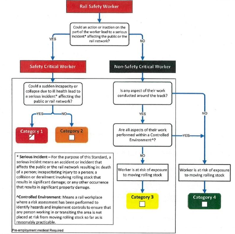
Source: Rail Commissioner
Acciona/RIC signalling team health assessments
Although the required health assessment category for the project role of TIC or signal electrician was not specified in Acciona procedures, the signal electrician held a current health assessment for a rail safety worker category 1 (safety‑critical worker) with no restrictions and the TIC had held a rail safety worker category 3 (non-safety‑critical worker) assessment with no restrictions.
However, the category 3 assessment for the TIC expired on 31 August 2020, around 3 months prior to the incident at Torrens Road. The TIC later advised the ATSB they had renewed their category 3 health assessment on 5 February 2021, with no restrictions.
The work on the AMPRN signalling system undertaken by the TIC and signal electrician as part of the GREP works was safety‑critical work and if undertaken by a RComm/SAPTA rail safety worker would require a category 1 health assessment for both the TIC and signal electrician. There was no evidence that the RComm, SAPTA or TPD reviewed the suitability of the health assessments of the RIC rail safety workers (particularly the TIC), as applied by Acciona for the GREP works, to determine if the RComm requirements/expectation for rail safety workers undertaking safety‑critical work on the AMRRN were satisfied.
Fatigue risk management program
Fatigue can have a range of influences on performance, such as decreased short-term memory, slowed reaction time, decreased work efficiency, reduced motivational drive, increased variability in work performance, and increased errors of omission (Battelle Memorial Institute, 1998). Due to these negative effects on cognitive performance, fatigue is a factor that increases the risk of transport accidents.
The Acciona procedure LLE617 Fitness health and hygiene described the process for managing fatigue and mental health. The procedure applied to direct employees and subcontractors. The procedure involved establishing project rules for the hours of work, arrangements for providing suitable welfare facilities, and the identification and risk assessment of tasks where fatigue could lead to mistakes that could result in the fatal injury of any person. Controls to manage fatigue related risk were then included in the safe work method statement for the associated task.
The Acciona project rules stipulated the maximum hours of work must not exceed the normal shift hours of 10–12 hours maximum per day, up to a cumulative total of 60 hours per week. The procedure allowed for working extended hours in situations where the type of work, track possession length or other circumstances, such as emergency works may arise. In such cases the requirement to work extended hours was to be approved and the guidelines described in the procedure applied to manage the hours worked.
RIC signal team
The signal team’s work hours were not determined from a set roster pattern but were governed by the requirements of the project’s daily schedule or the progress of a particular task on that day. The team typically commenced work onsite at around 0600 and worked to the completion of the tasks commenced that day.
In the week prior to the incident, the TIC and signal electrician recorded workdays of between 8.5 and 12 hours each day undertaking the signalling alterations to facilitate the track tamping works (Table 2). On one occasion, the signal electrician exceeded the 12-hour daily limit by 30 minutes. The reason for this or whether approval was sought/granted to work the extra time could not be established.
Table 2: Signal team hours of work
| Date | Tester in charge (hours include a 30-minute lunch break) | Signal electrician (hours include a 30-minute lunch break) |
| 23 November 2020 | Leave | Leave |
| 24 November 2020 | 0730 – 1630, 9 hours | 0700 – 1700, 10 hours |
| 25 November 2020 | 0700 – 1630, 9.5 hours | 0700 – 1730, 10.5 hours |
| 26 November 2020 | 0700 – 1530, 8.5 hours | 0700 – 1600, 9 hours |
| 27 November 2020 | 0700 – 1530, 8.5 hours | 0700 – 1600, 9 hours |
| 28 November 2020 | 0700 – 1530, 8.5 hours | 0600 – 1430, 8.5 hours |
| 29 November 2020 | 0700 – 1530, 8.5 hours | 0700 – 1530, 8.5 hours |
| 30 November 2020 | 0700 – 1530, 8.5 hours | 0700 – 1630, 9.5 hours |
| 1 December 2020 | Leave | 0700 – 1700, 10 hours |
| 2 December 2020 | 0600 – 1800, 12 hours | 0600 – 1830, 12.5 hours |
| 3 December 2020 | 0600 – 1930, 11.5 hours[1] | 0600 – 1930, 11.5 hours[1] |
| 4 December 2020 | 0600 – 1800, 12 hours | 0600 – 1800, 12 hours |
| 5 December 2020 | 0600 – 1730, 11.5 hours | OFF |
| 6 December 2020 | 4 hours | OFF |
| 7 December 2020 | 0600 – 1800, 12 hours | 0600 – 1830, 12.5 hours |
|
||
The signal electrician had worked 11 days consecutively before taking the 2 days off over the weekend prior to the incident. On commencing work on the day of the incident, the signal electrician self-rated their fatigue level as 4 out of 7 (a little tired, and not at their peak).[30] The signal electrician felt that they tended to be like that after a while on the big jobs.
The TIC had worked on each of 5 days prior to the incident. On 6 December 2020, the TIC undertook office-based work preparing plans and tools required for the coming week’s work. The TIC recalled obtaining poor sleep quality over the 3 nights of the weekend prior to the incident. On commencing work on the day of the incident, the TIC self-rated their fatigue level as 3 out of 7 (Okay, somewhat fresh).
Both the TIC and signal electrician stated they were aware of the need to individually manage fatigue levels, but also felt obliged to work toward meeting the project targets. Neither the TIC nor signal electrician had been provided with site‑specific training in the policies or procedures related to the management of fatigue during the GREP works.
Appendix B – Contracting in the rail industry
ONRSR guidelines
The Office of the National Rail Safety Regulator (ONRSR) published a range of fact sheets, guidelines and policies to provide the rail industry with key information on specific rail safety issues and legislative, regulatory and technical matters associated with the administration by ONRSR. These documents included information to duty holders about their duties and related obligations under the Rail Safety National Law (RSNL) when undertaking major projects involving contractor management.
The fact sheet General safety duties under the Rail Safety National Law – ‘upstream’ duty holders emphasised the RSNL embedded the principles of shared responsibility across a range of entities, including rail transport operators, rail safety workers and other persons such as designers, manufacturers and suppliers. ONRSR categorised some entities as ‘upstream’ as there would be greater scope for those entities to remove foreseeable hazards than a ‘downstream’ duty holder.
ONRSR noted upstream duty holders generally did not require accreditation for the activities they undertook. However, they still had a responsibility (general safety duty) to ensure they undertook their activities safely and in a way that did not affect the safety of the railway operations, themselves or others. The level and nature of the responsibility was dependent on the nature of the risks, and the capacity of the duty holder to control, eliminate or mitigate those risks.
RISSB guideline contracting in the rail industry
To supplement the ONRSR publications the Rail Industry Safety and Standards Board published the Accreditation and safety management systems guideline – contracting in the rail industry. The purpose of the guideline was to assist rail transport operators in understanding their responsibilities under the RSNL for engaging contractors to carry out rail operations and for contractors to gain an understanding of what is expected of them when they were engaged to carry out rail operations and specific rail safety work.
The guideline reflected the RSNL and ONRSR fact sheet in highlighting the principle of shared responsibility and accountability (general safety duty) to effectively manage rail safety when engaged in rail safety work, such as the design, commissioning or modification of rail infrastructure.
The guideline also noted the RSNL takes the principle of shared responsibility and strengthens its application by prescribing that:
- a duty under this Law cannot be transferred to another person
- a person can have more than one duty under this Law by being in more than one class of duty holder
- more than one person can concurrently have the same duty under this Law and each duty holder must comply with that duty to the standard required by this Law even if another duty holder has the same duty.
GREP arrangements
The South Australian Department for Infrastructure and Transport (DIT) encompassed the Rail Commissioner (RComm), the South Australian Passenger Transport Authority (SAPTA) and Transport project delivery (TPD). The RComm was the accredited rail infrastructure manager and rolling stock operator for the AMPRN. SAPTA managed the provision of passenger rolling stock operations and maintenance, train control functions and railway infrastructure maintenance under the RComm accreditation. The TPD, with a degree of involvement by SAPTA, managed the delivery of projects for the AMPRN, also under the RComm accreditation.
The TPD was the contract principal for the GREP that was undertaken by principal contractor Acciona in accordance with the Gawler rail electrification project alliance rail safety management plan (RSMP). The RSMP detailed how the alliance would meet the accreditation requirements of the RComm and general safety duties under the RSNL:
The purpose of the Rail Safety Management Plan is to describe the approach the Alliance will take (with the Constructor NOP [Acciona] being the Principal contractor), with WSP and Siemens [subcontractors] to manage the Gawler Rail Electrification Project Alliance. This Rail Safety Management Plan is focused on how the Project will comply with the safety requirements when carrying out railway activities, including survey, design, construction, commissioning, use, inspection, installation, modification, maintenance, repair, cleaning, decommissioning of rail infrastructure and the operation of rollingstock on the Adelaide Metropolitan Passenger Rail Network (AMPRN).
The Rail Safety Management Plan identifies how the Alliance delivery will meet the Rail Commissioner’s Rail Accreditation Requirements as a Rail Transport Operator. This is essential in order that the Rail Commissioner can fulfil its obligations under Rail Safety National Law and Regulations. The Principal will be relying upon the professed expertise of the Constructor NOP in Rail Safety to fulfil the Rail Commissioner’s obligations pursuant to the Rail Safety National Law.
The RSMP later detailed the arrangements for rail safety management:
In all cases the Rail Commissioner’s accreditation systems and processes will apply unless granted a waiver by the Rail Commissioner’s representative/s. The Rail Commissioner’s engineering standards, for the most part, reflect Australian Standards and Rail Industry Safety Standards Board (RISSB) documentation. As a contractor working under the Rail Commissioner’s accreditation, the Alliance will construct and carry out activities and reporting to the higher level whilst ensuring the Rail Commissioner’s accreditation is met.
The SAPTA final investigation report found that TPD and Acciona did not:
…have effective processes in place to provide assurance that the rail safety obligations of the Rail Commissioner's accreditation were being met by contractors and sub-contractors.
The statements in the alliance RSMP, SAPTA investigation and ONRSR fact sheet imply the RComm was a ‘downstream’ duty holder. The remaining entities, SAPTA, TPD, Acciona, RIC and the rail safety workers of the signal maintenance team were then upstream duty holders sharing responsibility for the rail safety duties associated with the development of safety management system procedures, work instructions and plans and approval processes to manage the specialised rail safety work required to alter the level crossings (including Torrens Road) as part of the GREP works.
Appendix C – Torrens Road inspection and test plan
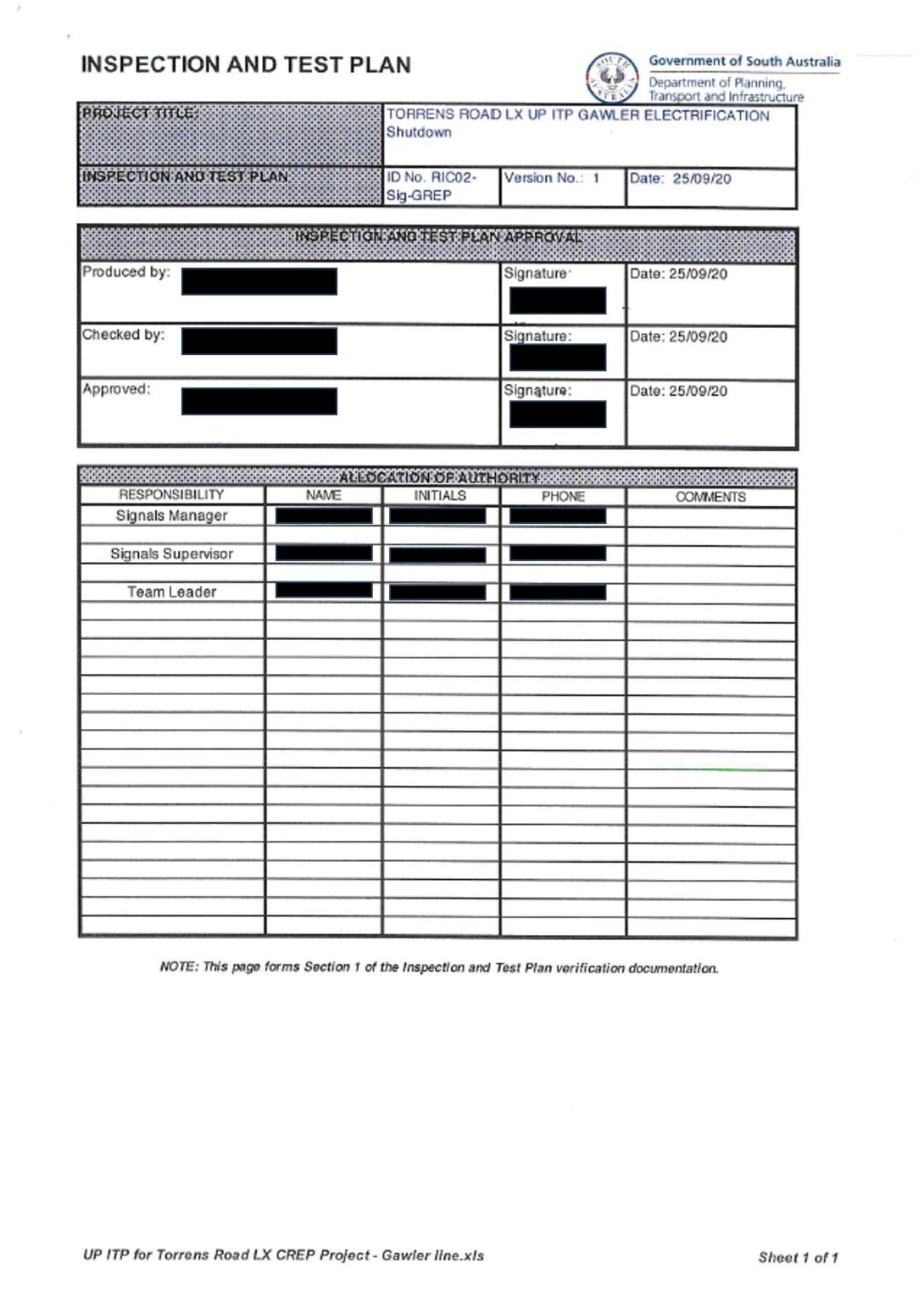
Source: South Australian Public Transport Authority, image modified by the ATSB to deidentify signatories
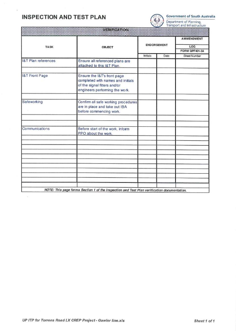
Source: South Australian Passenger Transport Authority
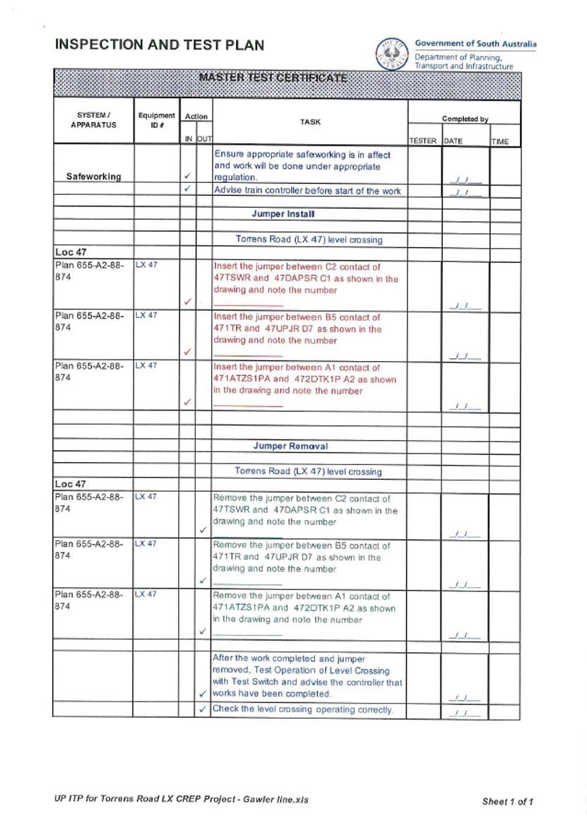
Source: South Australian Passenger Transport Authority
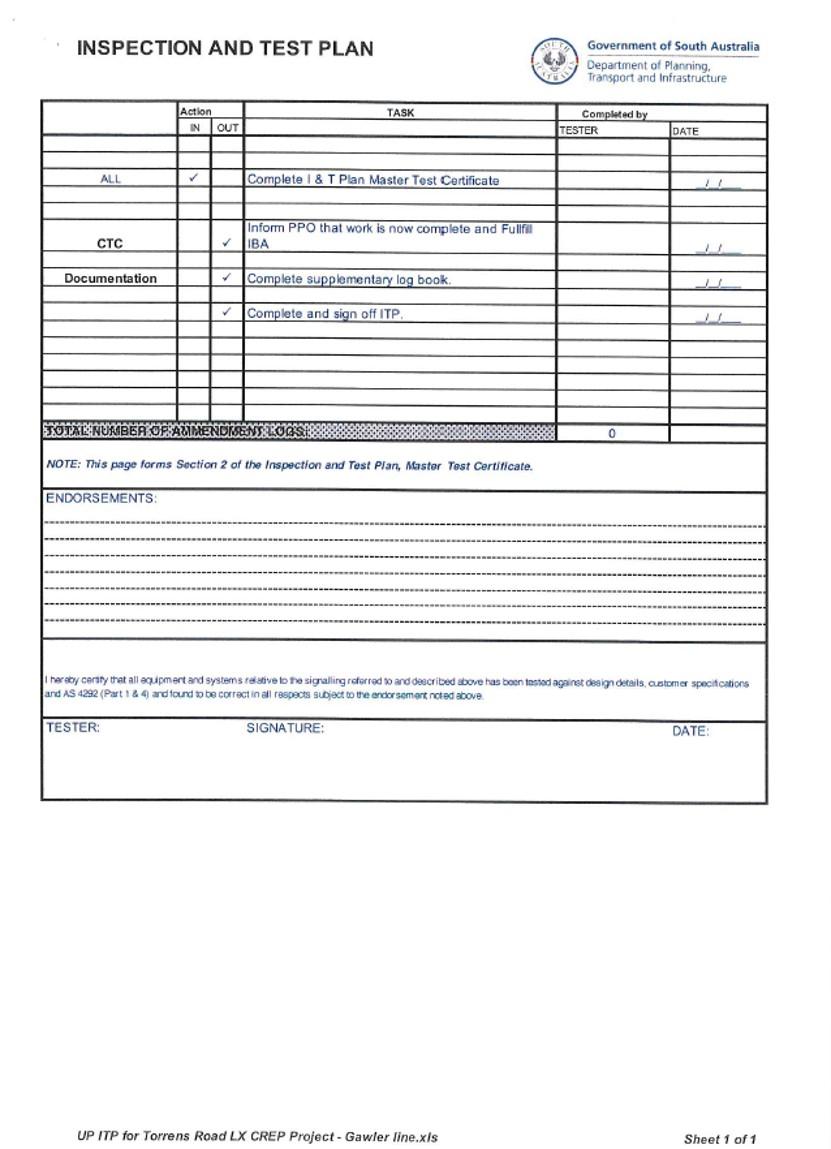
Source: South Australian Passenger Transport Authority
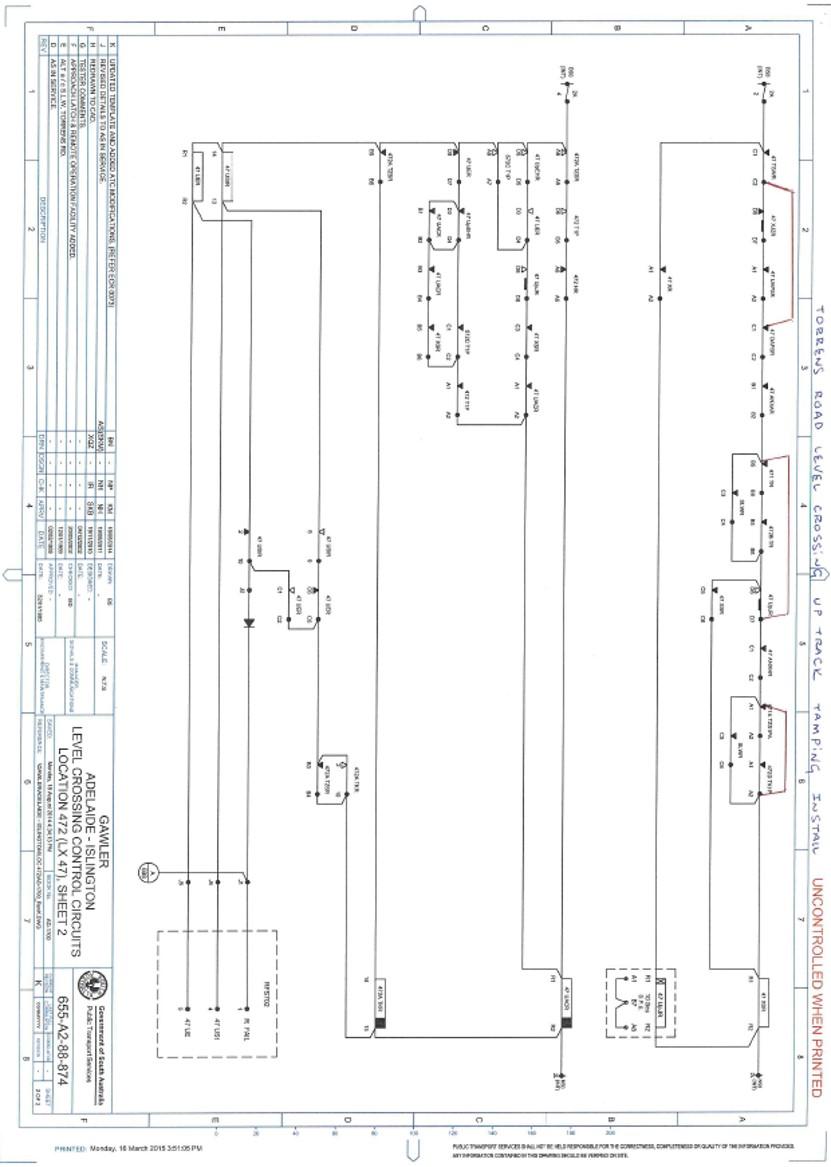
Source: South Australian Passenger Transport Authority
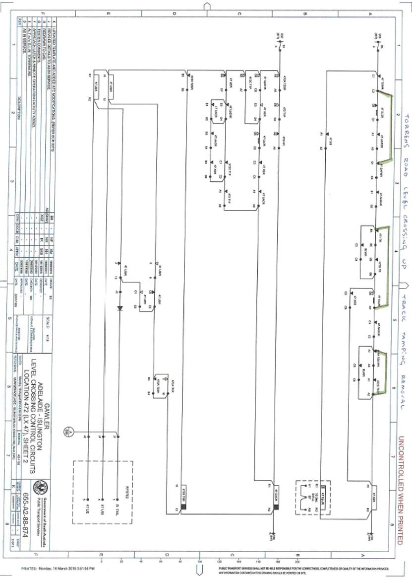
Source: South Australian Passenger Transport Authority
Purpose of safety investigationsThe objective of a safety investigation is to enhance transport safety. This is done through:
It is not a function of the ATSB to apportion blame or provide a means for determining liability. At the same time, an investigation report must include factual material of sufficient weight to support the analysis and findings. At all times the ATSB endeavours to balance the use of material that could imply adverse comment with the need to properly explain what happened, and why, in a fair and unbiased manner. The ATSB does not investigate for the purpose of taking administrative, regulatory or criminal action. TerminologyAn explanation of terminology used in ATSB investigation reports is available here. This includes terms such as occurrence, contributing factor, other factor that increased risk, and safety issue. Publishing informationReleased in accordance with section 25 of the Transport Safety Investigation Act 2003 Published by: Australian Transport Safety Bureau © Commonwealth of Australia 2025
Ownership of intellectual property rights in this publication Unless otherwise noted, copyright (and any other intellectual property rights, if any) in this report publication is owned by the Commonwealth of Australia. Creative Commons licence With the exception of the Commonwealth Coat of Arms, ATSB logo, and photos and graphics in which a third party holds copyright, this report is licensed under a Creative Commons Attribution 4.0 International licence. The CC BY 4.0 licence enables you to distribute, remix, adapt, and build upon our material in any medium or format, so long as attribution is given to the Australian Transport Safety Bureau. Copyright in material obtained from other agencies, private individuals or organisations, belongs to those agencies, individuals or organisations. Where you wish to use their material, you will need to contact them directly. |
[1] Acciona was the principal contractor for the railway infrastructure works.
[2] Work involved the operation of track tamping and ballast regulator machines to adjust the track alignment and reshape the ballast formation.
[3] Rolling stock movements on the up-rail line travel toward the Adelaide Railway Station.
[4] AMPRN track km marks measured from the 0 km mark at the Adelaide Railway Station.
[5] A competent worker who has carried out, is carrying out, or is about to carry out, rail safety work defined in the Rail Safety National Law.
[6] An electric circuit where current is carried through the rails and used to detect the presence of trains. Track circuits are used in the operation and control of points and signalling equipment.
[7] The IBA formally recorded that the AMPRN operations controller, or in this case the PPO in charge of the worksite, were notified and agreed to the modification of the nominated equipment prior to work being undertaken
[8] Control switch located in cabinet attached to the location case used primarily to operate the level crossing warning during maintenance work.
[9] ARTC track km marks at Torrens Road are measured from the 0 km mark at the Keswick rail passenger terminal.
[10] ARTC network control officer monitors do not display approach track circuit or level crossing status information for Hawker Street or Torrens Road level crossings.
[11] At the time of the incident, the Rail Commissioner was the accredited rail transport operator (rail infrastructure manager and rolling stock operator) for the AMPRN under the Rail Safety National Law (South Australia) Act 2012. See Organisational information section below detailing the contractual relationships associated with the GREP.
[12] Up direction toward Adelaide, down direction away from Adelaide and toward Gawler Central.
[13] Through the operation of a single line working function located within level crossing control circuit.
[14] This included the signal electrician who endorsed the review phase of the ITP approval process. The TIC was not involved in the production, review or approval phases of the ITP documentation.
[15] Errors were generally inconsistencies between the task description in the plan document and the marked-up circuit diagrams.
[16] Level crossings at Hawker Street, Pym Street and Park Terrace.
[17] SWMS RIC-031, Acciona – Signal support, Cable termination and Testing of signal infrastructure, version 3.
[18] A rail transport operator (RTO) can be a rail infrastructure manager (RIM) or a rolling stock operator (RSO) or a person who is both a RIM and RSO.
[19] In relation to the infrastructure of a railway, means the person who has effective management and control of the rail infrastructure.
[20] Rail-rail interface agreement, RComm and ARTC.
[21] The ARTC notice identified the GREP work area related to the Mile End to Crystal Brook route between the 3.8 km and 10.291 km marks on the ARTC network.
[22] Testing and evaluation of a product to assure compliance with its specification or other requirements.
[23] Confirmation that the particular requirements for a specific intended use are fulfilled.
[24] Control table: A part of the signalling system specification that defines the detail of the signalling controls for each signalling function.
[25] Aspect sequence testing verifies that only the correct aspect and route indication are displayed to the train driver.
[26] Principles testing shall be carried out to validate that the controls embodied in the system conform to signalling principles, performance specifications and site-specific operating requirements and the railway layout signalling plan.
[27] The inclusion of superfluous jumper wiring was common across all approved ITPs for the level crossing modification.
[28] Completion of a visual examination against the wiring diagram to confirm the termination contains the correct number of wires. Denoted on the circuit diagram by a small stroke across the wire next to the termination.
[29] Completion of examination for conductor continuity between wire termination points. Denoted by a small tick adjacent to the wire.
[30] The Samn-Perelli scale for self‑evaluating fatigue ranges from 1 (fully alert) to 7 (completely exhausted). A rating of 4 indicates ‘a little tired; less than fresh’.