What happened
On 4 July 2020, a Robinson Helicopter Company R44 Raven I helicopter, registered VH-NBY and operated on a private flight, departed an industrial property 3 km north of Broome Airport, Western Australia on a local flight. On board were the pilot and 3 passengers.
The pilot made a vertical departure to climb clear of obstacles before transitioning forwards. At that time witnesses heard a loud bang, and the empennage and tail rotor system of the helicopter broke away. The helicopter initially continued to climb and rotated to the right with increasing angular velocity.
Control of the helicopter was then lost, and it collided with terrain on its right side in a nose low attitude. The pilot and a passenger seated on the right side of the helicopter were fatally injured and the two passengers on the left side were seriously injured. The helicopter was destroyed.
What the ATSB found
Following the onset of vibration in the tail rotor pedals, an overstress fracture of the attachment lugs of the tail rotor gearbox input cartridge occurred. The source of the loading that led to the overstress fracture was not conclusively determined however, shortly after take-off, it led to separation of the tail rotor gearbox from the helicopter. This in turn led to fracture of the aft tail cone bulkhead and separation of all components attached to it, including the horizontal and vertical stabilisers.
Although presented with limited time and the stress associated with the emergency event, the pilot did not apply the pilot’s operating handbook procedure for responding to a tail rotor emergency. Prompt application of the procedure would have reduced the likelihood of loss of control, and therefore improved the potential for survivability. The pilot’s response may have been influenced by them not having a valid flight review for the helicopter type at the time of the accident.
Following identification of the vibration during the previous 2 flights, ground running of the helicopter was conducted by maintenance personnel, with no fault identified. However, as the vibration was reported to only occur in flight, and no defect was identified, it was reasonable to have concluded that the problem may still be present. As such, the safest next step (recommended by the helicopter manufacturer) was the conduct of a graduated flight check by a solo pilot. However, the next and final flight involved the conduct of a high‑power towering take-off from a confined area with 3 passengers on board.
The unnecessary carriage of passengers resulted in a significantly more severe outcome following the in‑flight break‑up.
Safety message
The pilot’s operating handbook for this helicopter stated that the onset of unusual vibrations can indicate impending failure of a critical component. Pilots should land as soon as possible and formally declare the helicopter unserviceable. Crucially, the helicopter should not be returned to service until the source of the vibration, both on the ground and airborne, has been found and rectified.
The registered operator of an aircraft has ultimate responsibility for its airworthiness. This accident demonstrates the importance of following a conservative troubleshooting process that minimises risk. The tools to manage airworthiness are freely published by the Civil Aviation Safety Authority and include the correct use of an aircraft’s maintenance release to clearly communicate the state of the aircraft and any required maintenance action.
Finally, private pilots do not have the benefit of regular flying and frequent training and checking afforded to commercial pilots. Therefore it is recommended that private pilots do not rely on minimum training and checking and currency to keep them safe. Instead they are encouraged to assess their risk profile and seek opportunities to maintain and develop their skills with a flight instructor.
The occurrence
Overview
At about 1436 local time on 4 July 2020, a Robinson Helicopter Company R44 Raven I helicopter, registered VH-NBY and owned and operated by a private pilot, departed an industrial property in Bilingurr, a northern suburb of Broome, Western Australia on a local flight. On board were the pilot and 3 passengers.
The pilot made a vertical departure to climb clear of obstacles before transitioning forwards. At that time witnesses heard a loud bang, and the empennage and tail rotor system of the helicopter broke away. The helicopter initially continued to climb and rotated to the right with increasing angular velocity.
Control of the helicopter was then lost, and it collided with terrain on its right side in a nose low attitude. The pilot and a child seated on the right side of the helicopter were fatally injured. An adult and a child seated on the left side were seriously injured. The helicopter was destroyed.
Detection of vibration
On 22 June 2020, VH-NBY was repositioned from the industrial site to Broome Airport, about 3 km to the south, by another helicopter pilot. During that approximately 6 minute flight, the pilot noticed a vibration in the tail rotor pedals which they described as ‘tapping with spoons’, adding that the sensation was noticeable but not strong. Upon landing, the pilot advised the owner of the aircraft (accident pilot) about the vibration. This was the first report of such vibration in this helicopter.
On the afternoon of 2 July 2020, the owner of the helicopter met a friend at Broome Airport. The owner flew VH-NBY indirectly back to the industrial site; the flight took around 18 minutes. During that flight, the owner sent a text message to the other pilot confirming that the helicopter had a problem.
Upon landing, further discussion about the vibration took place between the 2 pilots. It was reported that they were both concerned about the vibration, and that the owner described the vibration as roughness through the tail rotor pedals. Another person familiar with the reported vibration stated that the owner of the helicopter believed the vibration indicated a tail rotor balance problem. They said it was thought to be due to excessive application of paint to the leading edges near the tips of the tail rotor blades[1] at the previous 100 hourly scheduled maintenance inspection, around 4 flight hours prior. The owner requested the other pilot to contact their local approved maintenance organisation (AMO) to assess the vibration.
The AMO advised that the vibration was described to them not as tapping with spoons, but as ‘jackhammers’. It could not be determined if this change in description was due to a variation in pilot detection thresholds, worsening of the condition, or for emphasis.
Engineering actions
Maintenance troubleshooting
On the morning of 3 July 2020, the helicopter was due to be delivered to the AMO’s hangar at a nearby station. However, no pilots were available to relocate the helicopter, so the engineers attended the industrial site where the helicopter was located.
The chief engineer was the attending licenced aircraft maintenance engineer (LAME). The engineers reported that a review of maintenance records during preparation for the job identified that VH-NBY’s tail rotor blades had not been painted at the previous 100 hourly inspection, rather they were painted about 50 flight hours prior to that.
The planned maintenance activity was to measure and, if necessary, correct the dynamic balance of the tail rotor.
Witnesses stated that at around 1500 the engineering team, consisting of the owner of the AMO (a pilot), the chief engineer LAME, and an apprentice aircraft maintenance engineer (AME), arrived on site. The worksheet for the job stated, ‘Pilot reported tail rotor vibe’.
The owner of VH-NBY was also on-site when the AMO pilot and engineers arrived. They spoke briefly and the AMO pilot stated that they advised their intended course of action was to rub back the paint and measure dynamic balance of the tail rotor. The owner departed shortly after.
The team completed a daily inspection of the helicopter, including a close inspection of the tail cone, tail rotor, and empennage of the helicopter. This included searching for signs of damage, and/or movement or fretting in the aft flex plate, and all rivets and component attachment hardware. No issues were detected. The engineers then attached the electronic vibration monitoring equipment, and the AMO pilot operated the helicopter at flight rotor rpm on the ground. The tail rotor balance was confirmed to be well within limits.
The LAME reported that they then used fine grit sandpaper to make a cosmetic correction to the paint which had been previously applied to protect the leading-edge tips of the tail rotor blades. The dynamic balance of the tail rotor was measured again and found to be well within limits.
The AMO pilot reported that no vibrations were felt in the tail rotor pedals while the helicopter was operating. Additionally, the LAME leaned into the cabin and placed their hands on the tail rotor pedals and was unable to detect the described vibration. The AME also felt the tail skid, [2] attached to the bottom of the vertical fin, but did not detect any excessive vibration.
Requirement for further diagnosis
The troubleshooting identified to the AMO engineering team that it was highly unlikely the tail rotor balance was a potential source of the reported vibration. The electronic vibration monitoring equipment was removed from the helicopter. The LAME reported wanting someone to fly the helicopter as they wanted to determine if the reported vibration in the pedals was detectable in flight.
The AMO pilot elected not to hover or fly the helicopter in the industrial site as they felt that it was too confined and were concerned about foreign object damage if they hovered the helicopter. The site owner stated that they could have made the area safe for a test flight if they had been requested to do so.
The LAME advised that the test regime they wanted a pilot to apply was:
- hold the helicopter light on the skids, and check for vibration
- then if necessary, hover the helicopter and check for vibration
- then if necessary, fly the helicopter, and check for vibration.
The LAME completed the work pack, closing the job, and added a note that said:
Carried out tail rotor balance check. Found to be 0.05ips. No adjustments made. Nil defect found. Owner was notified flight check to be carried out.
The LAME stated that they passed the requirement for a maintenance check flight to the owner of the AMO. The owner of the AMO stated that they in turn advised both the owner and the pilot who first detected the vibration of the findings, of the requirement to fly the helicopter to provide more information.
The requirement for a maintenance check flight was not recorded on the helicopter’s maintenance release.
Post‑maintenance communication
The AMO engineering team stated that, as there was a fault reported, but no fault found during ground running, that a maintenance check flight was necessary to continue the troubleshooting to provide more information.
While still on-site with the helicopter, telephone records showed that the owner of the AMO called the pilot who first reported the vibration at 1530. The call lasted about 4 minutes. The owner of the AMO reported that during this call the pilot was advised that the tail rotor balance was good and that a pilot was needed to fly the helicopter. The pilot was unable to fly the helicopter that afternoon, however reported being told that the helicopter was ‘good to go’ and said there was no mention of a check flight requirement.
Immediately after that call, the owner of the AMO called the owner of the helicopter. They spoke for about 3 minutes. The owner of the AMO stated that during this call they advised the owner of the helicopter that the tail rotor balance was good, the engineers did not find anything wrong, and that a maintenance check flight was required. The owner of the AMO reported that the owner of the helicopter was also unavailable to fly the helicopter.
The owner of the AMO stated that they then intended to meet the first pilot in person to discuss the vibration issue, however they could not locate them, and was unable to contact them by phone again.
With respect to verbal notification of the requirement of a maintenance check flight for further diagnosis, there were differing accounts of whether this was communicated to the owner of the helicopter. A friend of the owner of the helicopter, who overheard the call on car speakerphone, agreed that the owner was told there was nothing wrong with the balance of the tail rotor, but disagreed with mention of the need for a maintenance flight.
Accident flight
The helicopter’s next flight was the accident flight on the afternoon of 4 July 2020. The flight was conducted as a private operation under the visual flight rules. The helicopter was configured with the front doors removed and rear doors installed.
The owner of VH-NBY had accommodation at the site and was familiar with the industrial location. Nearby buildings, high fences, vehicles, and trees necessitated a vertical departure. The prevailing easterly wind at around 10 kt favoured a departure over unoccupied ground.
The pilot started the helicopter at about 1428. The pilot then loaded 2 children and an adult into the helicopter. Due to the helicopter landing site being located within Class D airspace for Broome Airport, the pilot was required to obtain a clearance from air traffic control (ATC) to depart from the site. At 1434, the pilot contacted Broome ATC and received a clearance to depart the site. At about 1436, the pilot made an airborne call to ATC.
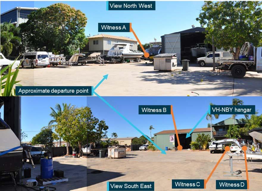
There were 4 witnesses at the industrial site at the time the helicopter took off (Figure 1). Their accounts of the departure varied between the pilot holding a low hover for a few seconds before conducting a steep departure, and the pilot making a steep departure directly from the ground without a hover.
Figure 1: Location of witnesses
Source: ATSB
Witnesses familiar with this departure process stated that nothing appeared out of the ordinary, the engine sounded normal and the helicopter climbed as expected. None of the witnesses saw or heard the helicopter make contact with any obstacles or foreign objects, or observed any items leave the cabin of the helicopter.
Nearby witnesses described hearing a bang as the helicopter reached an estimated height of about 55 ft. One witness described the sound as like a ‘metal bar hitting a metal pole’. Recordings from closed circuit television (CCTV) nearby showed a rearward movement of the upper vertical fin, and the helicopter nose pitch up, followed by parts releasing from the tail section. The empennage, tail rotor gearbox and surrounding components separated and tumbled from their attachments at the rear of the tail cone. A small section of one tail rotor blade was also identified in the security vision departing from the helicopter.
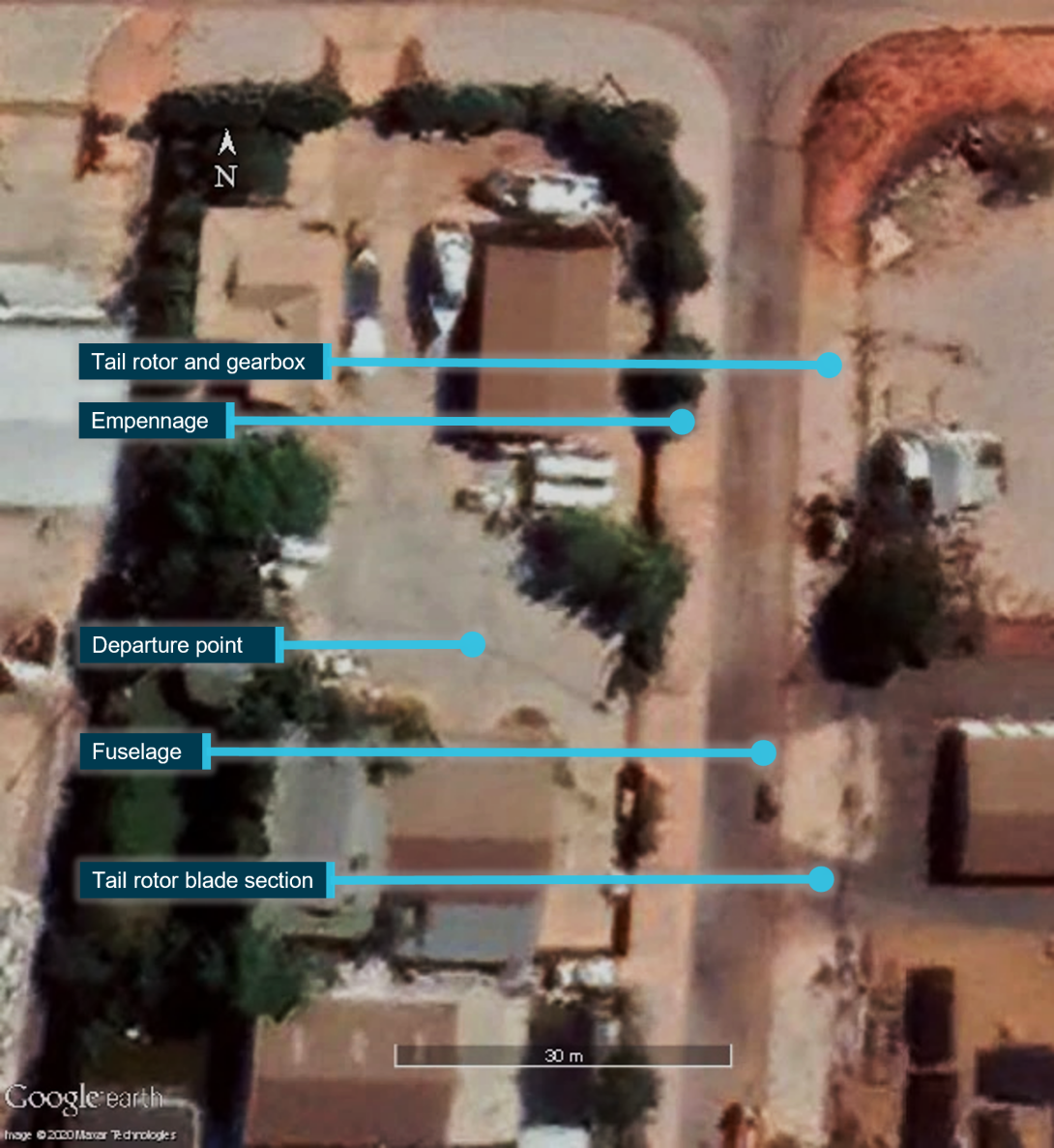
The helicopter continued climbing to about 75 ft while rotating twice to the right with increasing angular velocity, before rolling and descending rapidly toward the ground. The helicopter impacted heavily onto a road surface, about 30 m from the departure point (Figure 2). Calculations from a security camera recording showed that the duration from the first moment of the disturbance of the vertical fin to a total loss of control of the helicopter, was about 2.7 seconds.
The helicopter struck the road surface predominantly on its right side and in a nose-low attitude. The pilot, and a passenger, both seated on the right side of the helicopter were fatally injured. The front and rear left seat passengers were seriously injured. The helicopter was destroyed.
Figure 2: Location of aircraft and components following in-flight break-up
Source: ATSB
Post-impact events
Witnesses and neighbours were able to reach the occupants and begin recovery within seconds of the event. A forklift was used to lift the fuselage by the mast fairing to allow access to the right side of the passenger compartment. Australian Defence Force personnel and Western Australia Police Force officers were also nearby and quickly conducted triage and treatment prior to fire and ambulance services arriving.
The helicopter was fitted with fuel tank bladders. Although a bladder had punctured as a result of the impact, and fuel had subsequently leaked, there was no post-accident fire. Aviation Rescue Fire Fighting Service and Department of Fire and Emergency Services units were deployed to the accident site and together contained the fuel spill and fire risk.
The police, with assistance from the State Emergency Service (SES), closed the street. Police officers from the forensic crash unit documented the accident site and maintained the integrity of the scene until the ATSB arrived. Police and SES personnel protected the accident site for the duration of ATSB’s on-site activities.
Context
Pilot information
Licence
The pilot attained a Private Pilot Licence (Helicopter) PPL(H) in May 2015 and held an endorsement for the Robinson R44 helicopter. To exercise the privileges of this flight crew licence, a pilot is required to have a current aviation medical certificate and helicopter flight review (HFR). A logbook for the pilot was not able to be located, however a family member estimated the pilot’s total flying experience to range between 1,200 and 1,500 flight hours.
Medical
The pilot had previously held a Class 2 aviation medical certificate, however that certificate expired on 9 March 2019, and had not been renewed. A review of the pilot’s post-mortem report found no evident natural disease.
Toxicology results showed a 0.012% urine alcohol concentration and zero blood alcohol concentration. The pathologist that conducted the autopsy indicated this was probably from consumption, although a possibility of post-mortem alcohol production also existed.[3] Furthermore, the pathologist considered the low level of alcohol in the urine to be toxicologically insignificant as there was zero alcohol detected in the blood.
Flight review
An HFR is an opportunity for pilots to practice in-flight emergencies with an instructor and to demonstrate the required competence to safely operate a helicopter. HFRs for private pilots have a validity of 2 years. In discussing the aim of a flight review, the Civil Aviation Safety Authority (CASA) published Civil Aviation Advisory Publication (CAAP) 5.81-01 - Flight crew licensing flight reviews, which stated:
Commercial Pilot Licence (CPL) and Air Transport Pilot Licence (ATPL) holders are often part of a system that involves some form of training and checking, whereas the average private pilot is not. With the passage of time and lack of practice some skills and knowledge can degrade. A flight review affords the opportunity to restore these degraded skills and gain new knowledge.
The flight review must be seen in the context of a broader aviation safety philosophy. The flight review, although important (and required by legislation), is one process that contributes to continuing pilot proficiency and consequently the safety of flight. A flight review every two years does not, in itself, ensure safety. Safety is achieved when each pilot takes responsibility for a continuing process of hazard identification and risk management for their own aviation activities.
The Civil Aviation Safety Authority (CASA) required, via document CASA 007/17,[4] that HFRs for Robinson helicopters were to be conducted in Robinson helicopters. The pilot’s last HFR in a Robinson helicopter was a flight of 1.9 hours on 20 November 2017. That HFR expired 20 November 2019.
Following endorsement on a Bell 505 in the United States (US), to validate the endorsement in Australia, the pilot undertook an HFR in a Bell 505 on 31 May 2018. The validity of that HFR was extended to 1 December 2020 by CASA’s COVID management process through EX5720.
While the pilot of VH-NBY had a valid review for other types, in accordance with CASA 007/17(8), they did not have a valid HFR for the Robinson R44 at the time of the accident.
Endorsements
The pilot began a low-level endorsement in October 2018, which was not completed. An external load rating was not conducted or issued at any point.
Despite not having obtained the qualifications required to conduct these activities, the ATSB identified that the pilot had previously performed low‑level flight and external load work.
Training in tail rotor emergencies
The pilot completed PPL(H) training with 74.8 hours of flight time. Despite being required to demonstrate competence in emergencies, including tail rotor failures, to pass a licence test, the pilot’s student progress checklists did not record tail rotor emergencies (failure in forward flight and hover) being briefed or taught. However, on 6 May 2015 the pilot undertook a flight test and tail rotor malfunctions were recorded as tested and passed.
At the time of the accident the pilot had last conducted tail rotor emergencies in a helicopter 2 years and 2 months prior and had not conducted tail rotor emergencies in a Robinson Helicopter for 2 years and 8 months.
Helicopter information
General information
The Robinson Helicopter Company R44 Raven I is a 4‑place, light helicopter, powered by a Lycoming O-540-F1B5, 6-cylinder, horizontally-opposed piston engine. It has a 2‑bladed main rotor system and a conventional 2‑bladed tail rotor.
The R44 helicopter type was approved by the US Federal Aviation Authority (FAA) on 10 December 1992 and approved in Australia on the basis of that certification in 1994. The R44 Raven I was introduced in January 2000.
At the time of the accident, there were 558 R44s on the Australian civil aircraft register. Total R44 helicopters production was around 7,100 helicopters. Together, the worldwide R44 fleet had flown an estimated 17.7 million flight hours.
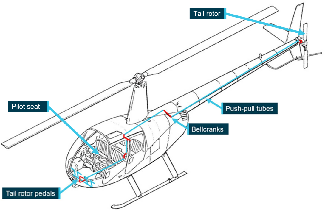
The tail rotor pedals of the R44 are connected to the tail rotor through a series of bellcranks and push-pull tubes (Figure 3). That is, a continuous physical linkage. Therefore any dynamic movement, such as vibration, associated with the tail rotor system would be transmitted to the pedals.
Figure 3: R44 tail rotor control system
Source: Robinson Helicopter Company, annotated by ATSB
VH-NBY maintenance history
The R44 Raven I helicopter involved in the accident, serial number 2544, was built in May 2018 in the US. It was test flown, then disassembled and shipped to a distributor in Australia by the manufacturer. On 11 September 2018 the helicopter was reassembled by a Robinson Helicopter Company distributor in Queensland and placed on the Australian register as VH-NBY.
Maintenance conducted on VH-NBY is detailed in Table 1.
Table 1: VH-NBY maintenance history
| Date | Maintenance | Total time | Notes |
| 30 May 2018 | Built at RHC | 0.0 | Serial number #2544 |
| 11 September 2018 | Re-assembled in Australia | 4.0 | Issued certificate of airworthiness on 12 September 2018 |
| 28 March 2019 | SB-96 | 46.70 | SB-96 Change clutch actuator time delay assembly |
| 13 May 2019 | 100 hourly inspection | 88.62 | Nil issues |
| 20 July 2019 |
100 hourly inspection SB-99 |
186.41 | SB-99 Battery Electrolyte leakage |
| 29 July 2019 | Cargo hook installation | 195.03 | Onboard Systems Cargo Hook fitted |
| After 25 August 2019 | MR blade repair | 224.6 |
Probably due to main rotor bird strike. Large bird (brown booby) No documentation of inspection or repair in logbooks or maintenance releases Evidence of paint on blade tip in location of damage |
| 9 October 2019 | 100 hourly inspection | 248.80 |
Removed emergency locator transmitter Cylinder head temperature probe replaced TR blade tips painted and balanced to below 0.2 ips |
| Around 24 November 2019 | Inspection panel replaced | Not recorded |
Oil filler access panel cracked at hinge replaced under warranty No evidence of inspection or repair in logbooks or maintenance releases |
| 24 January 2020 | Front right bubble replaced | 262.35 | Bubble cracked by unrestrained front door on ground Replacement recorded on maintenance release by engineer |
| 4 June 2020 |
100 hourly inspection 300 hourly inspection SB-103 |
286.90 | Number 2 cylinder changed due to compression loss SB-103 MR tip plates complied with (95 days overdue) |
| 24 June 2020 | Hard wired Spidertracks tracking system | Not recorded | Carried out fault finding to aircraft tracking device. Replaced damaged wiring |
| 3 July 2020 | Pedal vibration inspection | 291.00 | Tail rotor paint lightly sanded Tail rotor balance checked Recorded vibration 0.05 ips |
Sources: VH-NBY maintenance logbooks, interviews, Western Australia Police Force
Tail rotor blade refinishing
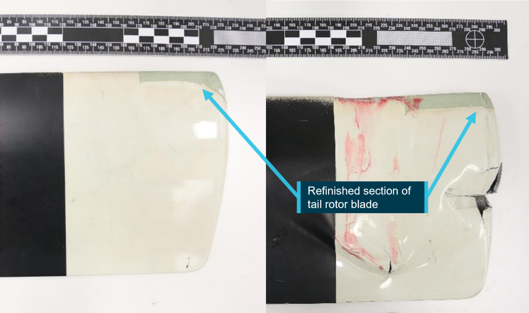
Most areas of Australia present harsh conditions for operation of helicopters. Coastal areas have salt laden air, sand, and dust that may erode main rotors and tail rotors at a rate high enough to render components unserviceable before their life-limit[5] is met. Rotor blade erosion damage has potential to significantly increase the operating costs of helicopters. To combat this, refinishing the tips of Robinson Helicopter tail rotor blades is common practice in Australia (Figure 4).
The R44 maintenance manual allowed for repaint of tail rotor blades where erosion exists. Section 30-00 of the manual stated:
The tail rotor blades are constructed with aluminium skins and root fittings. Maintaining the paint finish will reduce corrosion and erosion.
Section 30-36 carried instructions for painting the tail rotor. Adding paint to the blade tips adds weight that could upset the balance of the tail rotor. Therefore, following painting, the balance of a tail rotor was required to be checked and adjusted if necessary.
The tail rotor blades on VH-NBY were last refinished on 9 October 2019 and the balance was found to be within limits.
Figure 4: Refinished area of tail rotor blades (Paint transfer and damage due to accident)
Source: ATSB
Maintenance release
An aircraft’s maintenance release (MR) (CASA form 918) is a document used to record and communicate the airworthiness of an aircraft between registered operators, pilots, and engineers. It included a section (Part 2) for defects to be recorded (and cleared), and a section (Part 3) to record daily inspections and flight hours.
Part 2
A person with knowledge of a defect is required to record the defect in part 2 of the MR. This would cause the MR to cease to be in force and serve as a notice to pilots and engineers that the aircraft is not to be flown until the defect is resolved. Following the detection of vibration during the flight conducted on 22 June 2020, no defect was recorded on the MR.
When a defect was endorsed, resulting in the MR ceasing to be in force, a qualified person would have to declare the defect resolved in Part 2, to restore the airworthy status of the aircraft. This can include restoration of airworthiness after a successful maintenance check flight.
A requirement for a maintenance check flight following 100‑hourly maintenance on 4 June 2020 was endorsed on the MR. This endorsement was cleared by conducting the flight and finding no defects. While the requirement for a maintenance check flight following the tail rotor balance check of 3 July was written on the approved maintenance organisation’s (AMO) work pack, it was not annotated on the helicopter’s MR.
Part 3
Part 3 of the MR required certification of the daily inspection by a qualified person[6] prior to flight, and the recording of flight hours to manage the ongoing maintenance requirements of the aircraft. If the daily inspection had not been certified, the aircraft must not be flown.
Part 3 of VH-NBY’s MR was incomplete. The only flight recorded was the maintenance check flight of 4 June 2020. The helicopter was flown on 4 separate days after that date, with only one daily inspection being recorded. This does not necessarily indicate that daily inspections were not conducted. For example, the owner of VH-NBY was photographed checking the oil level of VH-NBY on 2 July 2020. This was part of the daily inspection for this helicopter. However, due to the lack of documentation, the extent to which the helicopter was inspected on these dates could not be determined.
No flight time was recorded for any of these 4 flights; however the helicopter was fitted with an hour meter which recorded flight time.
Pilot’s operating handbook advice on vibration
In the safety tips and notices section of the Robinson R44 pilot’s operating handbook (POH), there was advice on vibration and checking for resolution of a problem. It stated:
7. A change in the sound or vibration of the helicopter may indicate an impending failure of a critical component. If unusual sound or vibration begins in flight, make a safe landing and have the aircraft thoroughly inspected before flight is resumed. Hover helicopter close to the ground to verify the problem is resolved, and then have aircraft reinspected before resuming free flight.
The following tail rotor driveshaft failure in the United Kingdom (UK) in 2003 demonstrated the success of this staged approach in a situation whereby the source of vibration was not as expected and could not be identified on the ground.
Robinson R44 Clipper, G-KAZZ, tail rotor driveshaft failure, UK, 2003
The helicopter was being flown to Sywell for a 50 hour maintenance inspection when it developed a lateral vibration with a frequency coincident with main rotor rotation. It was able to land successfully at Sywell where the main rotor drive system was examined. As no apparent problems were identified an engineering test flight was carried out to see if the vibration event could be replicated. Normal handling failed to reproduce the event so a towering climb from the hover was initiated. This produced worsening vibration levels, an increase in engine manifold pressure, and difficulties in yaw control necessitating an immediate descent and landing. After landing it was discovered that the tail rotor was not rotating. An inspection of the tail rotor drive system revealed a failure of the tail rotor drive shaft aft of the whirl mode damper bearing. The subsequent AAIB [Air Accidents Investigation Branch] investigation could not find any evidence to explain the cause of the failure….
The decision to carry out a test flight however, given the circumstances, was considered to be the normal course of action to take when troubleshooting a defect of this kind. The engineers had already undertaken a full inspection and testing on the ground of the main rotor system, with no defect detected. They continued testing the helicopter in a logical manner and were fully aware of the implications of undertaking a test flight. The quick reaction of the test pilot following the onset of the failure kept the situation under control, no one was injured and the helicopter suffered only minor damage.
Controllability
Centre of Gravity
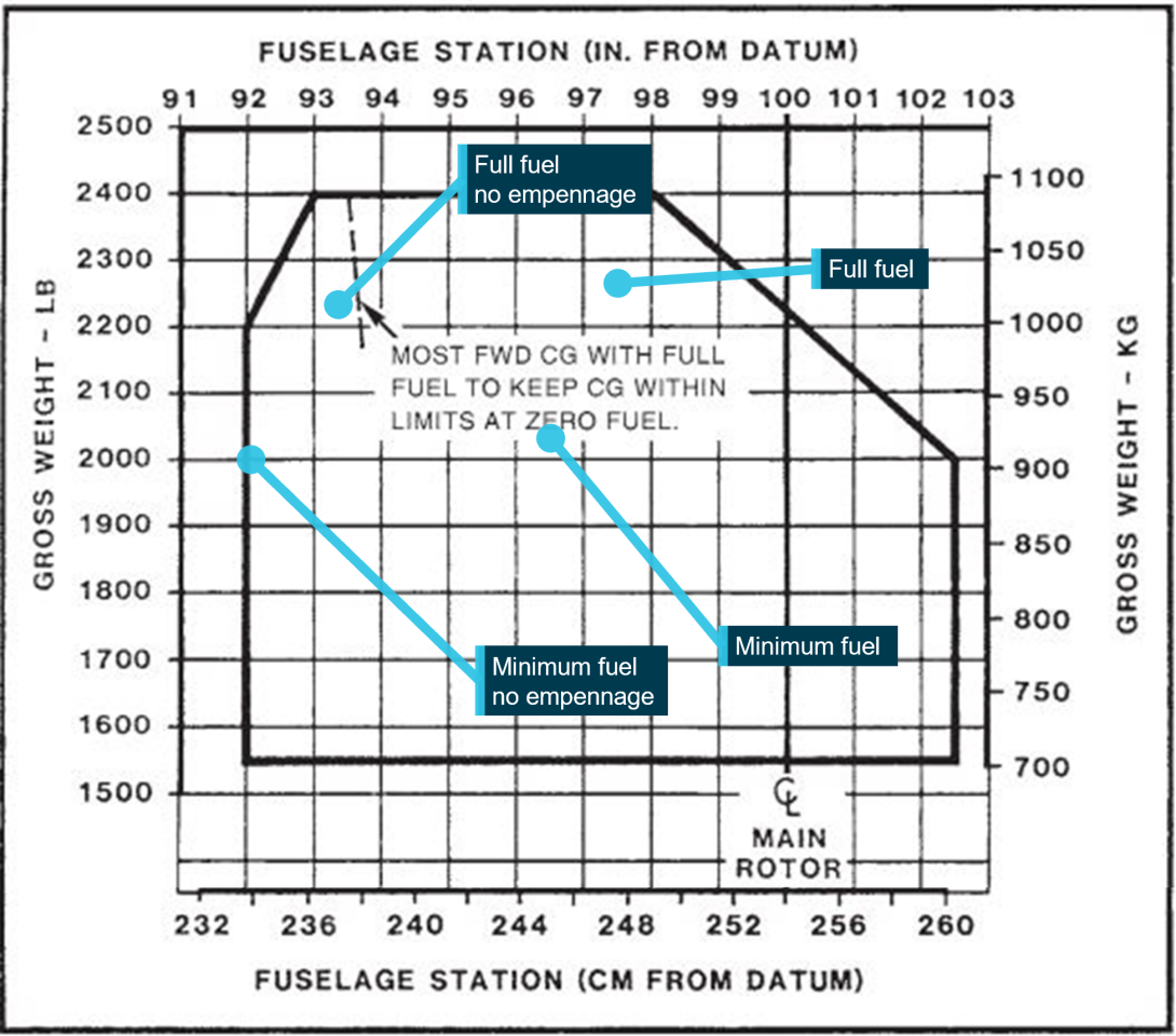
The components lost in flight had a direct effect on controllability of the helicopter. Along with the obvious loss in primary yaw control, a significant change of centre of gravity occurred (Figure 5).
The ATSB recovered almost all of the components that had separated from the rear of the helicopter. These components weighed 17.7 kg. A weight and balance calculation used 18 kg to account for some missing fragments, and oil from the tail rotor gearbox.
As fuel leaked from the wreckage and no fuel records were kept, it was not possible to determine exactly how much fuel was onboard VH-NBY for departure. However, with full fuel the helicopter would have been below the maximum allowable all-up weight. The minimum required flight fuel was calculated to be 34 L. This was based on a 10 minute flight with 20 minutes of reserve and 4 L of unusable fuel. The actual fuel load was probably higher as 30 L of fuel was drained from the wreckage and an unknown, but substantial, quantity of fuel was released post‑accident.
While there was a large shift forward in centre of gravity it is highly likely that VH‑NBY’s centre of gravity remained within limits following the in-flight break-up (Figure 5).
Figure 5: Centre of gravity calculations
Source: Robinson Helicopter Company, annotated by the ATSB
Emergency procedure
R44 POH
Loss of the empennage of the helicopter is an extreme event, causing significant disruption to the controllability of the helicopter. The helicopter’s POH includes information on handling a loss of tail rotor thrust. The manufacturer confirmed that symptoms of this occurrence are nearly identical to a loss of tail rotor thrust.
The POH stated:
LOSS OF TAIL ROTOR THRUST IN FORWARD FLIGHTFailure is usually indicated by nose right yaw which cannot be corrected by applying left pedal.
1. Immediately enter autorotation
2. Maintain at least 70 KIAS if practical
3. Select landing site, roll throttle off into overtravel spring, and perform autorotation landing.
LOSS OF TAIL ROTOR THRUST IN HOVER
Failure is usually indicated by nose right yaw which cannot be stopped by applying left pedal.
- Immediately roll throttle off into overtravel spring and allow aircraft to settle
- Raise collective just before touchdown to cushion landing.
Energy available for engine off landing
The energy to successfully land a helicopter in an engine off situation comes from a combination of available potential and kinetic energy in the form of height, forward speed and rotor RPM. A pilot can utilise that energy to maintain drive to the main rotor and create lift.
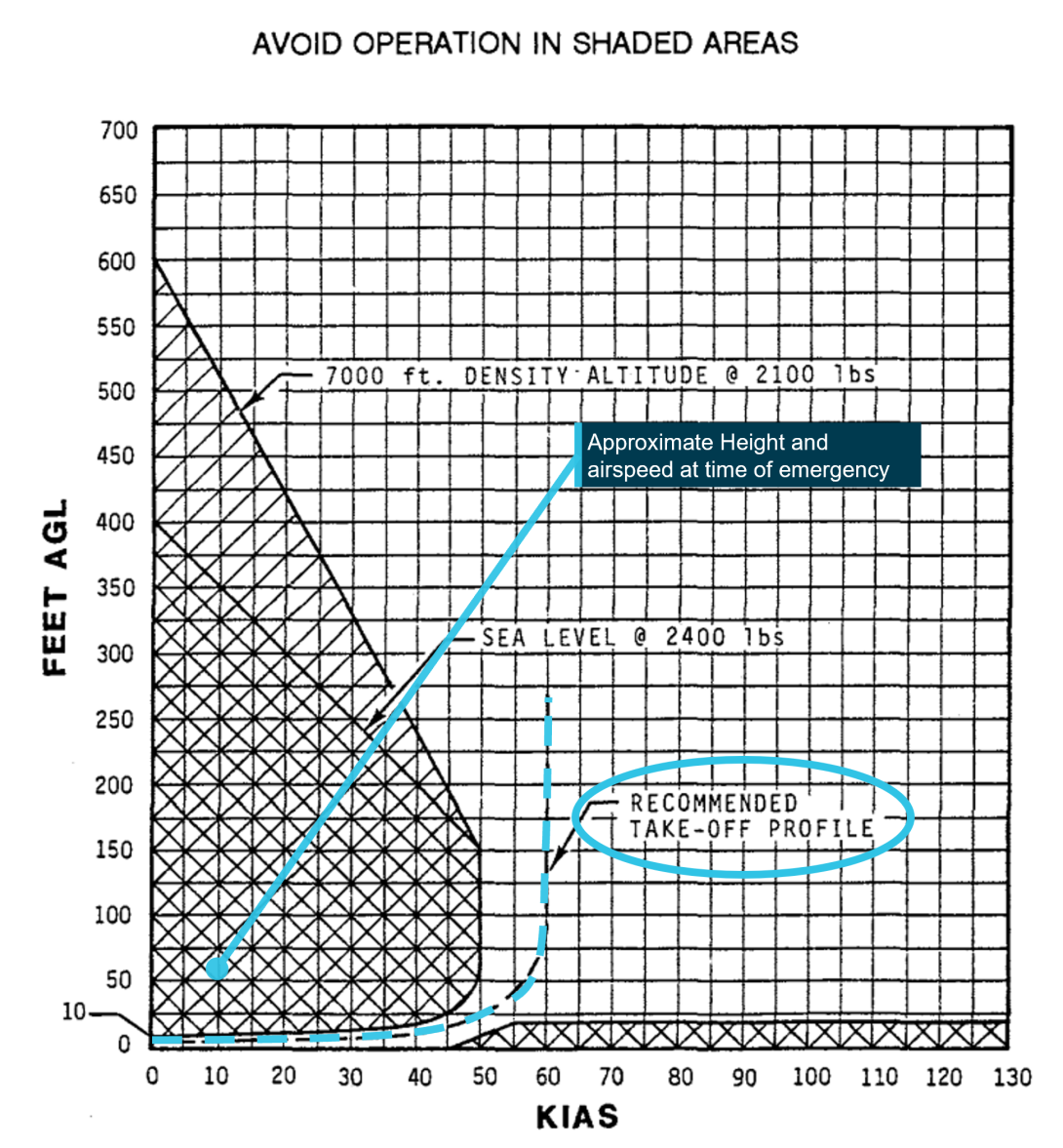
As shown in Figure 6, at the time the empennage and tail rotor system detached the helicopter was being operated within the R44 height/velocity diagrams ‘avoid’ area. In practice, this meant that there was probably insufficient total energy to be able to conduct the required power‑off landing without damaging the helicopter.
Figure 6: R44 Raven I height / velocity diagram
Source: Robinson Helicopter Company, annotated by the ATSB
Site and wreckage information
Location
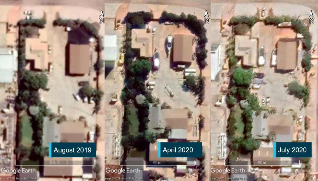
The industrial site at Bilingurr contained private residences, a hangar, and a large shed. The fenced property provided storage for assets of an associated business. The effect of COVID-19 restrictions meant that more equipment than normal was stored in Bilingurr (Figure 7). As a result, the site was more confined than usual, presenting an increased risk for helicopter operations.
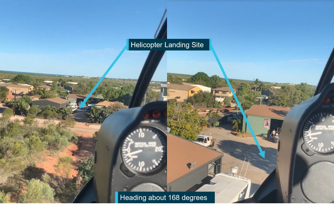
The site at Bilingurr was used as the home base for the helicopter and partly intended for use for the arrival or departure of helicopters (Figure 8). The operator stated that the site was operated as a basic helicopter landing site (HLS)[7]. However, helicopters had been used at the site for at least 4 years. The CASA civil aviation advisory publication (CAAP) 92(2)[8] detailed guidelines and provided advice for development and operation of helicopter landing sites. The site did not meet the guidance of CAAP 92(2) with respect to arrival and departure profiles, nor was it required to do so.
Figure 7: Bilingurr site equipment storage
Source: Google Earth, annotated by the ATSB
Figure 8: Helicopter landing site at the industrial site in Bilingurr
Source: Supplied, annotated by the ATSB
Meteorological information
Weather data recorded by the Bureau of Meteorology showed that at the time of the accident the weather was suitable for helicopter operations. There were clear skies, the temperature was 33º C, and the wind was a south-easterly at about 19 km/h.
Recorded closed‑circuit television imagery
A portion of the flight shortly after take-off and then most of the subsequent break-up sequence was captured on three nearby closed-circuit television (CCTV) security cameras (Figure 9). A fourth CCTV camera at Broome Airport also captured the occurrence. The recordings were of high value to the investigation. Analysis of the recordings identified the break-up sequence and showed that the rotor rpm was operating in its normal range at the time of the accident.
The break-up sequence of events is described in Table 2. Images showing the continuity of the event recorded by the closest cameras are shown in Figure 10.
Figure 9: Nearby CCTV locations and relative fields of view
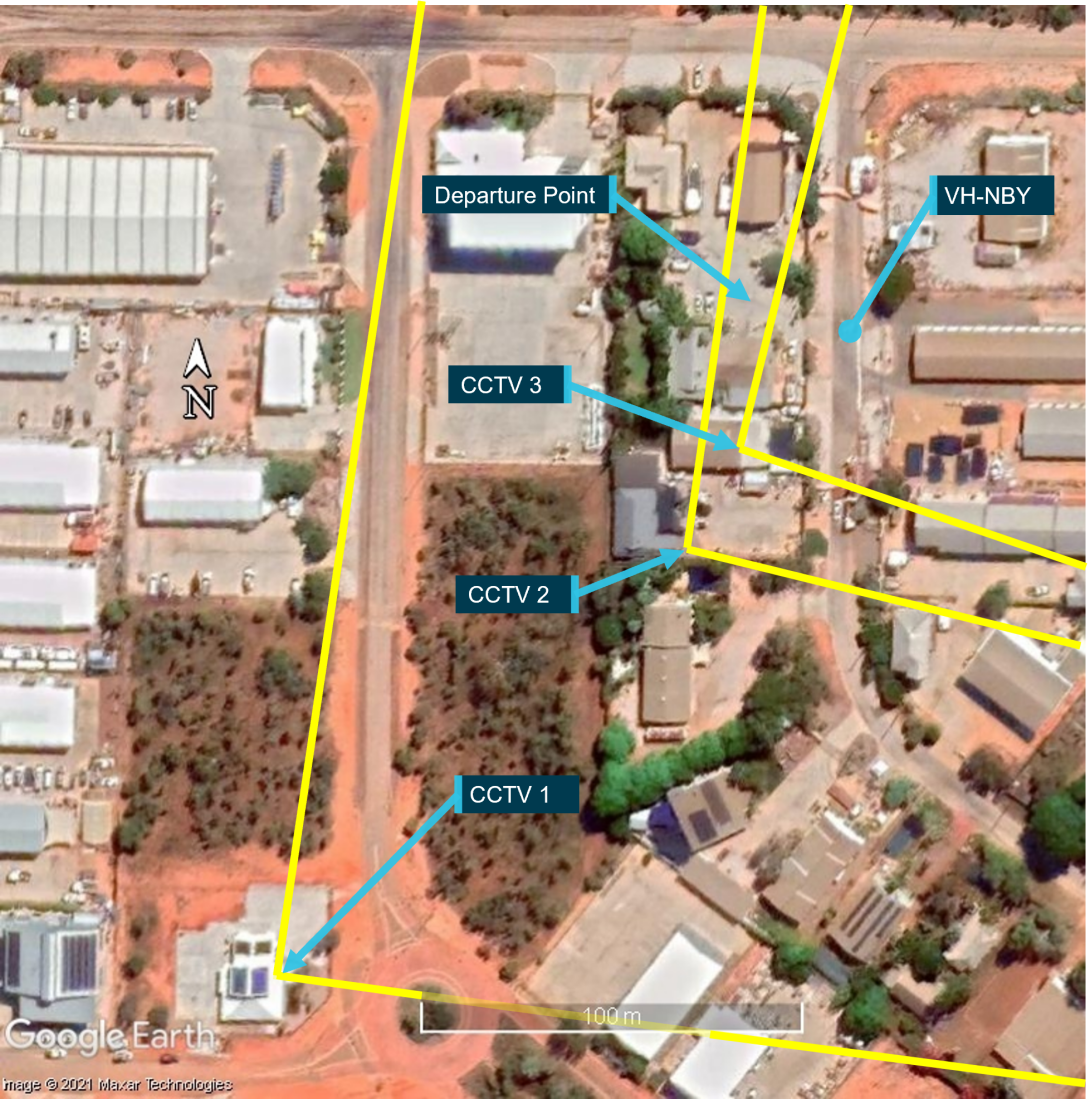
Source: Google Earth, annotated by the ATSB
Table 2: CCTV timeline of event
| Time (seconds) | CCTV 1 | CCTV 2 | CCTV 3 |
| 0.0 | Helicopter climbs to around 30 ft at a calculated rate of about 325 ft/min. | Not in frame. | Not in frame. |
| 0.5 | Helicopter enters extreme top left of frame. | ||
| 3.7 | Helicopter enters frame. | Helicopter exits frame, not yet rotating. | |
| 4.0 |
Empennage vertical fin rotates top back/bottom forward around its mount. Estimated moment of tail rotor blade contact with fuselage. |
All but empennage of helicopter in frame. Section of tail rotor blade enters frame at high speed. |
Not in frame. |
| 4.2 | Helicopter nose pitches up. | Helicopter nose pitches up. | Section of tail rotor blade enters frame. Helicopter shadow shows helicopter rotating to the right. |
| 4.7 | Tail rotor gearbox visible behind stabiliser. Empennage separates. | ||
| 6.3 | Helicopter leaves frame climbing and rotating. | ||
| 6.7 |
Helicopter continues climbing and completes a full right rotation. Fuselage rolls about 20° to the left. Estimated moment of loss of control. |
Not in frame. | Clear shadow of the helicopter in frame shows completion of first rotation to right. |
| 7.7 | Helicopter continues climb and makes a second full right rotation. | Shadow shows second full rotation. | |
| 8.1 | Helicopter continues to rotate. It rolls and descends before becoming inverted. The main rotor contacts the right skid and both separate. | Helicopter re-enters frame with 90° right roll before becoming inverted. | Helicopter re-enters frame with 90° right roll before becoming inverted, and impacting ground nose low on its right side. |
Figure 10: Continuity of the accident sequence on nearby security cameras (CCTV)
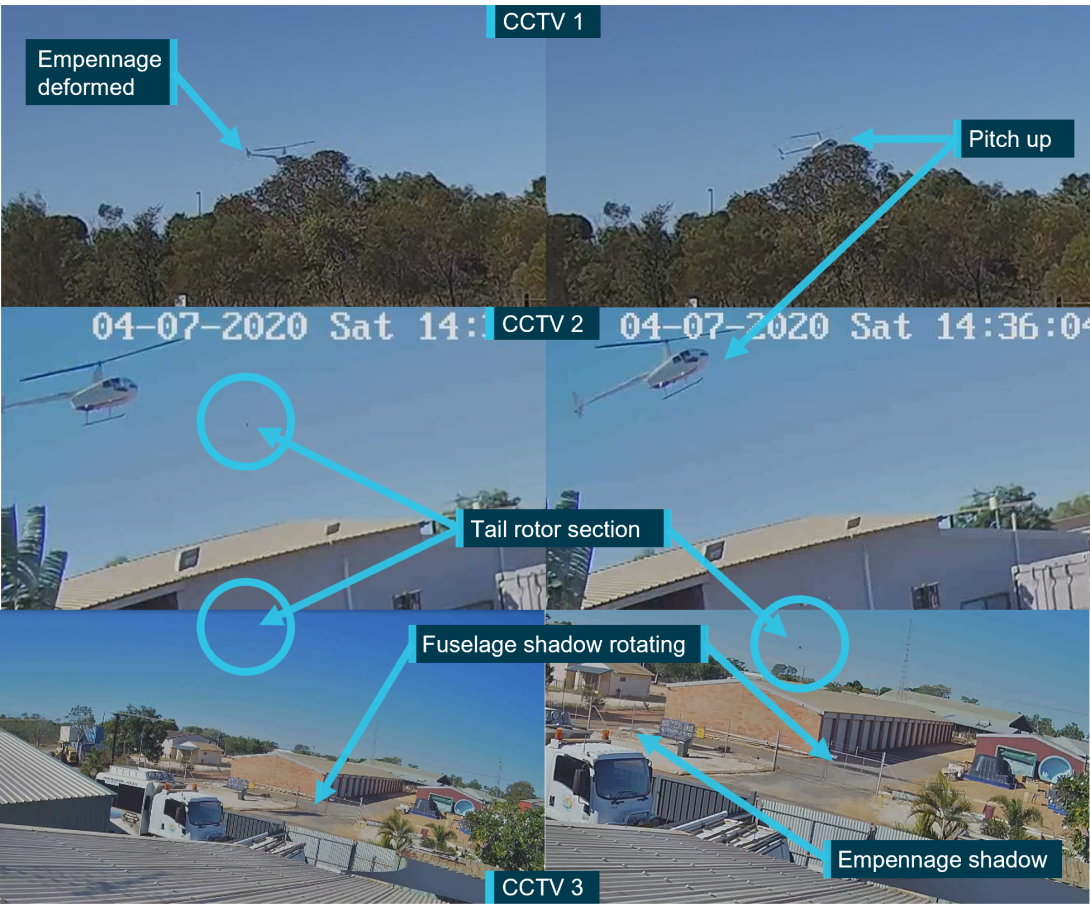
Source: Western Australia Police Force, annotated by the ATSB
Wreckage information
All components of the tail section of the helicopter were accounted for and recovered at the accident site. All fastener and assembly hardware was recovered. Most of the components and fragments were found between 0‑36 m to the left of the intended track (Figure 2). There were 4 main wreckage areas comprising the fuselage, tail rotor blade tip, empennage, and tail rotor system, including the tail rotor gearbox (TRGB).
The fuselage lay on its right side and was complete apart from the right skid tube, the outboard half of one main rotor blade, and components from the aft flex-plate back. The tail rotor blade section was found 13 m from the fuselage, slightly to the right along the intended track. The empennage which carried a large section of aft tail cone bulkhead, was left of the intended track at a distance of 30 m from the fuselage. The TRGB and tail rotor system were also left of track, 36 m from the fuselage.
On-site examination showed that the aft tail cone bulkhead had fractured together with the input cartridge lugs, and that the tail rotor blades had struck the empennage and tail cone. To determine the sequence and mechanism of failure, the components were transferred to the ATSB technical facilities in Canberra, Australian Capital Territory for detailed examination.
Flight controls
Inspection of the wreckage confirmed that all components and attaching hardware of the flight controls were present and displayed no pre-accident damage. As such, continuity of all flight controls almost certainly existed prior to the in-flight break-up. Furthermore, following the loss of the empennage and tail rotor system, control of the cyclic, collective and throttle would have remained available to the pilot.
Tail cone
Onsite examination showed that the forward end of the tail cone was securely attached to the fuselage of the helicopter with correct attaching hardware. At the aft end of the tail cone, the skin was cut and torn through from repeated impact and flailing of rotating driveshaft components (Figure 11).
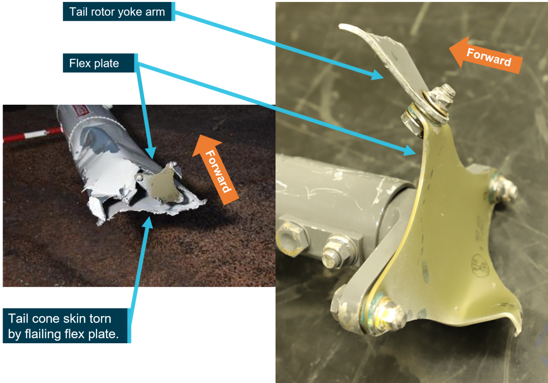
Source: ATSB
Aft flex plate
The rear of the tail rotor drive shaft sustained severe rotational contact against the tail cone structure. Inspection confirmed that the attachment hardware between the tail rotor gearbox input yoke, rear flex plate, and tail rotor drive shaft was correctly oriented and all attaching hardware (nuts, bolts, and washers) was assembled in accordance with Robinson requirements.
The fracture surfaces of the flex plate attachment were examined at very high magnifications using a scanning electron microscope (SEM). The fracture surface was comprised of predominantly dimples from micro-void coalescence indicating the fracture was by ductile overstress. There was no evidence of pre-existing fatigue cracking that might have otherwise predisposed the flex plate to premature fracture.
Tail rotor gearbox input yoke
Both arms from the input yoke to the TRGB fractured and separated from the body of the yoke (Figure 12). The fracture surfaces of one of the yoke arms contained distinct progression bands that suggested the component had fractured under cyclic loading. Subsequent optical and SEM examination of the fracture identified features of cyclic overstress. There was no evidence of fatigue or any other damage that might have indicated the yoke arm fractures occurred prematurely.
It was concluded that the attachment yoke arms had fractured from cyclic bending loads during the break-up sequence.
Figure 12: Tail rotor gearbox input yoke
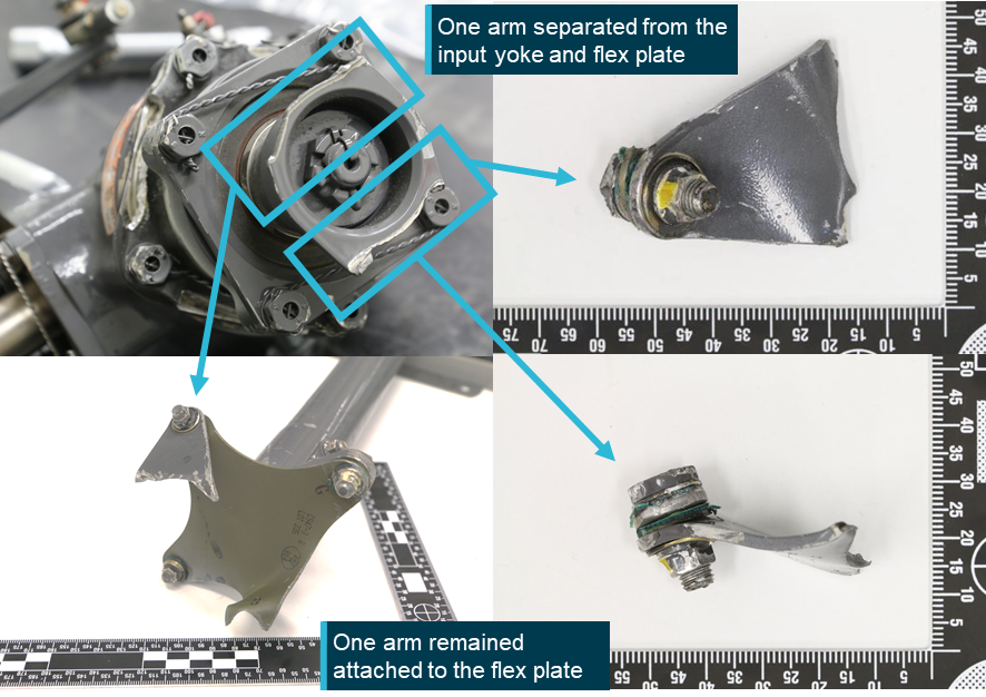
Source: ATSB
Aft tail cone bulkhead
During the conduct of this investigation, the ATSB was advised of aft tail cone bulkhead fractures caused by impact to the horizontal stabiliser during ground handling in Robinson helicopters. The ATSB made a request of the Australian helicopter industry to provide information on these events (see Appendix B). Received information showed that damage during ground handling was unlikely to be a factor in this occurrence as these incidents produced a different fracture plane, compared with that present in VH‑NBY. Additionally, the associated impact damage typically present on stabiliser surfaces of affected helicopters, was not present on VH‑NBY.
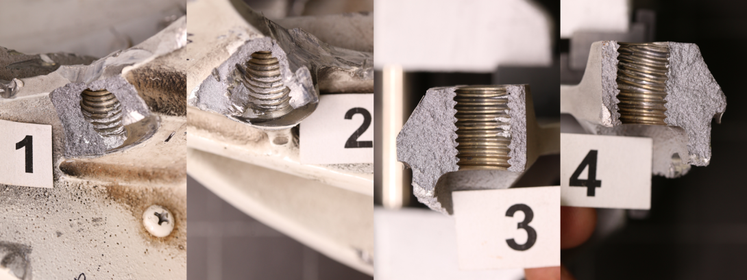
Examination of the aft tail cone bulkhead from VH-NBY showed that it had fractured into several pieces (Figure 13). The primary fracture plane was through the horizontal centre line. All 4 attachment bolts and their threaded inserts[9] had been pulled free of the bolt hole within the casting (Figure 14). The fracture features of the bulkhead attachment bolt holes where the TRGB input cartridge had been mounted, were consistent with tensile overstress. There was some mechanical damage and associated impressions on the mating surfaces, but no evidence of fretting was found on any of the contact surfaces that might have otherwise indicated the bolts had insufficient tension.
SEM examination of the fracture surfaces confirmed a predominantly brittle surface of cleavage facets.[10] Some minor locations showing shrinkage pores[11] and micro-dendritic defects[12] were observed, however, these were limited along the fracture surface and not considered to be contributory to the break-up. The SEM examination confirmed that the cast bulkhead had fractured in a brittle instantaneous manner. There was no evidence identified to indicate the surfaces had been rubbing, nor was there evidence found of any progressive crack mechanism (fatigue) through the structure.
Figure 13: Aft tail cone bulkhead and input cartridge (shown in red)

Source: ATSB
Figure 14: Threaded bolt holes of the aft tail cone bulkhead
Source: ATSB
The interior of the fragmented tail cone structure, which was still attached to the aft tail cone bulkhead section showed curling of the skin and contact marks from rotating contact damage by the flailing drive shaft.
Empennage
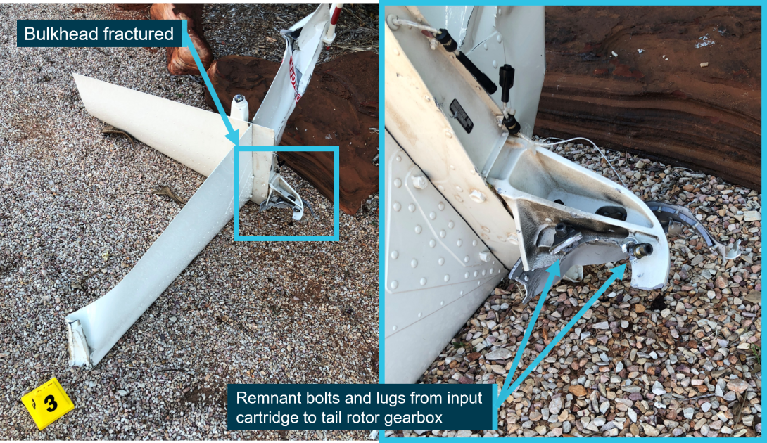
The empennage separated following fracture of the aft tail cone bulkhead. There was impact damage on the lower vertical fin from a tail rotor blade strike and the upper fin had ground impact damage following the break-up. The horizontal fin also displayed minor levels of post break-up damage. The bulkhead had fractured horizontally and retained the bolts and a lug from the TRGB input cartridge (Figure 15). The tail skid situated below the lower vertical fin was unmarked.
Figure 15: Empennage
Source: ATSB
Input cartridge examination
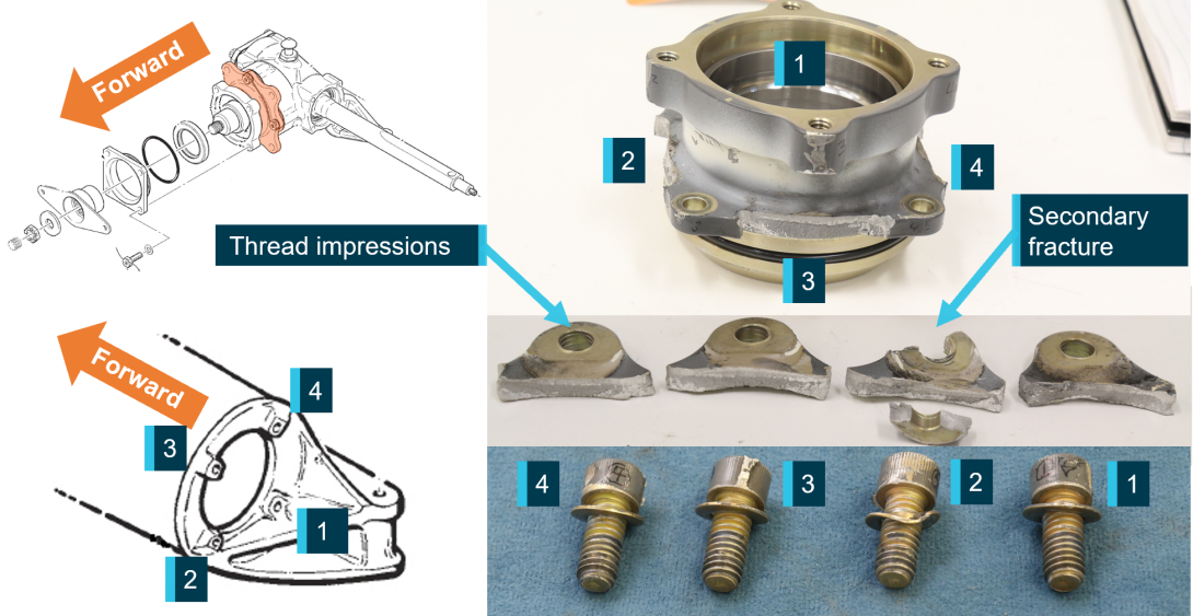
The input cartridge is a machined part fitted to connect the TRGB to the aft tail cone bulkhead. It contains 4 lugs designed for bolting to the bulkhead. The examination confirmed that all 4 attachment lugs that abutted against the cast bulkhead had fractured during the accident sequence. Each of the lugs had deformed and twisted across the section, and the hole within each lug was elongated or deformed and a thread profile from the attachment bolts had been impressed within the bore of the holes (Figure 16).
The contact areas of each lug showed no evidence of fretting or wear damage that might suggest the surfaces had been ‘working’ or that the input cartridge had been loose and moving about during service.
The fracture surfaces of each of the 4 lugs were examined in detail using an optical microscope. The surfaces were clean and free of deposits, flat in shape and texturally quite ‘rough’, indicating that the overstress fracture had occurred in a ductile manner. There was the no evidence of beach marks[13] indicative of fatigue fracture.
A secondary zone of about 1.5 mm in depth was present on each fracture surface. A detailed study of the fracture surfaces of all 4 lugs was completed at high magnifications using an SEM. The examination confirmed that all four fracture surfaces were comprised of two regions, a planar ‘flat’ zone and a larger zone of overstress dimples. There was no evidence of crack progression in any of the lugs that might suggest that the input cartridge had contained a metallurgical defect (pre-existing cracking) that would otherwise have led to an increase in net section stresses from operational loads.
Figure 16: Tail rotor input cartridge
Source: Robinson Helicopter Company and ATSB, annotated by the ATSB
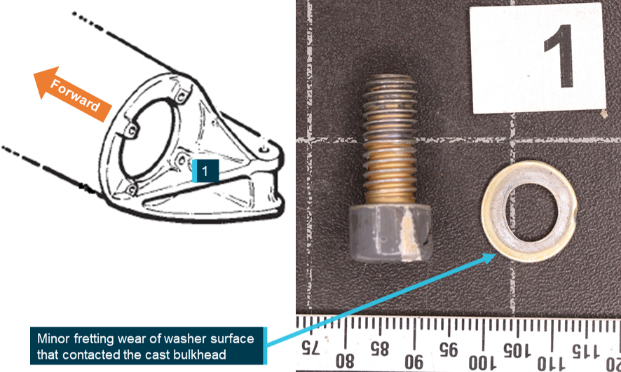
Some evidence of micro movement of the fitted components was found on the washer surface facing the cast bulkhead at location 1 (Figure 17). Here, minor fretting and elongation of the washer was observed.
Figure 17: Input cartridge attachment bolt
Source: Robinson Helicopter Company and ATSB, annotated by the ATSB
Tail rotor gearbox and input cartridge manufacturing records
In 2012 the Robinson Helicopter Company changed the aluminium alloy used to manufacture the input cartridge from 2024 T351 to 7075 T7351. The change in material strengthened the input cartridge to improve outcomes in tail rotor strikes. VH-NBY’s tail rotor gearbox input cartridge was made from 7075 T7351 aluminium alloy.
Examination of the manufacturer’s TRGB and input cartridge build and quality records showed that TRGB serial number 8702 was assembled in a lot of 10 units. During the assembly process, the gear tooth contact pattern and backlash were documented by the manufacturer, and no-issues were identified in the records.
The manufacturer also provided the ATSB with component specifications, which the ATSB used in examination of the components from VH-NBY. The input cartridge was sectioned and measured against its design drawing. Measured dimensions of the input cartridge were confirmed to meet the dimensions of the approved design.
Samples of the input cartridge were also destructively sectioned for metallurgical analysis. Both the chemistry and the strength levels of the material comprising the input cartridge were assessed against the material specifications[14] listed in the design drawing. Semi-quantitative chemical analyses showed that the cartridge alloy was consistent with the chemical composition of aluminium alloy 7075, as specified. Hardness testing showed that the cartridge alloy exceeded the specified minimum strength requirements.
In summary, the input cartridge was found to conform to the approved design specifications.
Disassembly of the TRGB
All hardware associated with the TRGB was accounted for, both at the accident site, and again during the ATSB laboratory examination.
The TRGB and input cartridge were x-rayed prior to disassembly and no anomalies were noted. The TRGB exhibited no internal faults, gear meshing errors or evidence of abnormal operation that might have otherwise been contributory to the failure. Additionally, the magnetic chip plug and oil remaining in the TRGB were checked and no debris, metallic or otherwise, was identified.
Disassembly of the TRGB was witnessed by involved parties.[15]
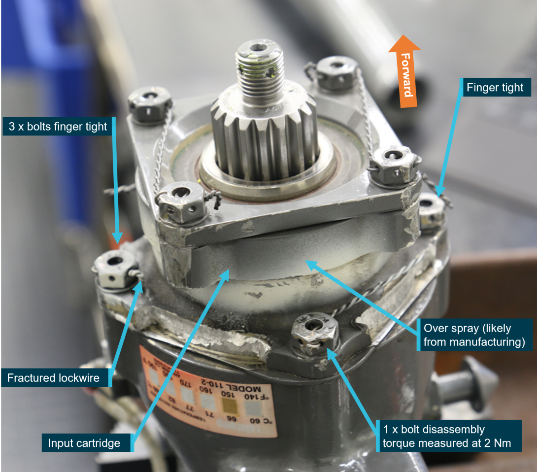
The fastening torque of the bolts joining the input cartridge to the tail rotor gearbox casting was identified to be very low. Additionally, the adjoining lock wire that formed a secondary security to the keep the bolts tensioned and in place had been pulled away from the security hole on to the bolt head (Figure 18). The anodised surface at the interface of the input cartridge to the TRGB displayed no wear to the finished surfaces. The contact surfaces for each of the washers was examined and there was no evidence of significant fretting.
The absence of any significant wear/fretting to these surfaces indicated that the loosening of the bolts probably occurred from a shock/impulse load through the gearbox on separation from the bulkhead casting.
Figure 18: Tail rotor gearbox and input cartridge
Source: ATSB
Tail rotor pitch control
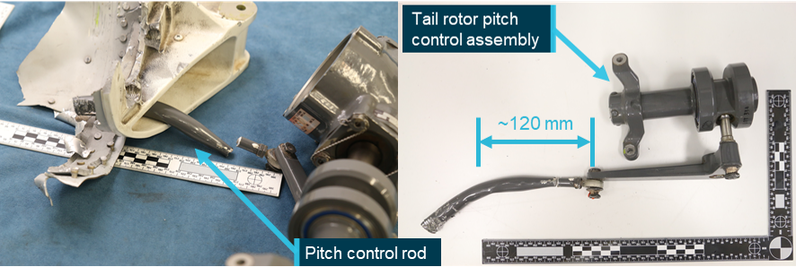
Bending of the pitch rod confirmed that it was intact and remained connected after the separation of the tail rotor gearbox from its connection to the cast bulkhead (Figure 19). Measurements showed that a 120 mm length of the tail rotor pitch control rod (neutral pedal position) had bent around the bulkhead before fracturing at the bell crank rod end.
Fracture surfaces at the rod-end connection to the bell crank were characteristic cup-and-cone that indicated ductile overstress. The tail rotor pitch change rod was severed during the accident sequence from repeated rotating contact damage at the aft flex plate position. Additionally, there were no anomalies detected in the bell crank, pitch control assembly or pitch links.
Figure 19: Pitch control rod
Source: ATSB
Tail rotor system
The TRGB, tail rotor pitch control assembly, and tail rotor hub and blades assembly had separated from the empennage and were situated 36 m away from the main wreckage.
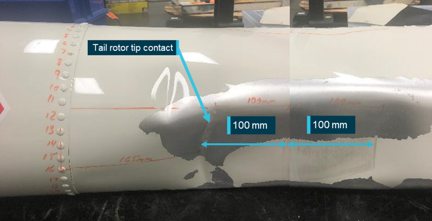
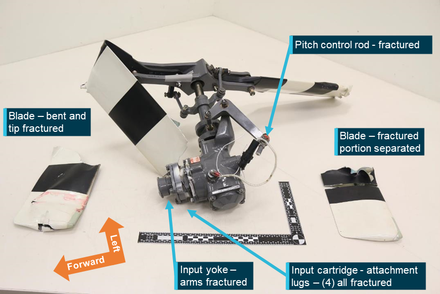
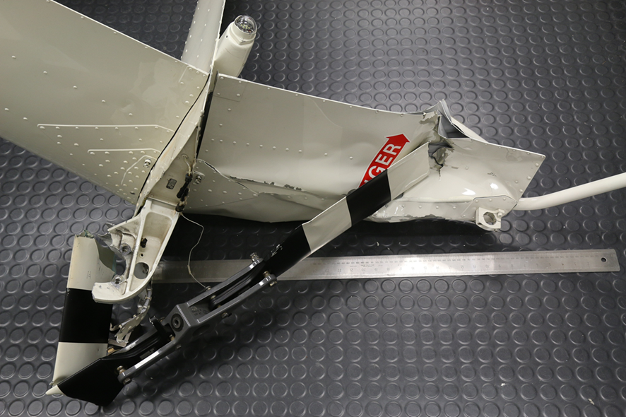
The examination identified that one tail rotor blade had struck the underside of the tail cone (Figure 20), and tail rotor guard, and a prominent hole had been pierced through the bonded tip cap (Figure 21). The other blade had struck the lower vertical fin (Figure 22).
The tail rotor blade skin surrounding the point of fracture for both blades were examined optically and using an SEM. They showed predominantly angular tear ridges[16] and ductile morphological features[17] on the fracture surfaces. There was no evidence of a pre-existing defect such as fatigue, nor were there any anomalies noted with the blade construction.
The skin surrounding the point of fracture was examined optically and using an SEM with predominantly angular tear ridges and ductile morphological features on the fracture surfaces. There was no evidence of a pre-existing defect such as fatigue, nor were there any anomalies noted with the blade construction.
Figure 20: Tail rotor contact with tail cone
Source: ATSB
Figure 21: Tail rotor system (underside view)
Source: ATSB
Figure 22: Tail rotor contact with lower vertical fin
Source: ATSB
Analysis of the break‑up sequence identified that the TRGB was almost certainly separated from the end of the tail cone at the time of tail rotor blade contact with the tail cone, and with the lower vertical fin.
Tail rotor blade deposit analysis
Examination of each tail rotor blade surface at high magnification using a binocular microscope confirmed the presence of the surface deposits, which was further analysed. Exposure of the blade surfaces to ultra-violet light also identified numerous fluorescing substances.
The ATSB consulted the Australian Centre for Genomics at the Australia Museum, and using their supplied DNA test kits, swabbed the blade surfaces and sent the samples to the museum for analysis. The genomic testing reported no evidence of wildlife DNA that might otherwise indicate the surface deposits were from a wildlife strike.
Summary of examination
Examination by the ATSB of the aircraft on-site, of CCTV footage, and laboratory examination of tail section components found that:
- there were no pre-existing defects identified in any of the rotating or static tail section components
- there were no missing fasteners or assembly anomalies
- the TRGB exhibited no evidence of abnormal operation
- the TRGB assembly records showed no abnormalities at the time of manufacture
- the input cartridge was found to conform to all aspects of the Robinson design specifications
- the input cartridge attachment lugs had no evidence of fatigue cracking and had fractured in overstress
- the low fastening torque of the input cartridge was likely a consequence of loads experienced during the in‑flight break-up
- micro movement was found on a washer surface facing the cast bulkhead
- there was no evidence that the tail rotor blades had been subject to a wildlife strike.
Previous occurrences
Worldwide Robinson R44 fleet
The ATSB analysed worldwide accident data to identify previous occurrences involving loss of the empennage and/or TRGB. That review identified 8 accidents that bore similar post-accident damage signatures to the in‑flight break-up of VH-NBY. The ATSB received valuable support from the Flight Safety Foundation’s Aviation Safety Network, the United Kingdom Air Accidents Investigation Branch, and from the US National Transportation Safety Board (NTSB) to identify and analyse previous relevant accidents.
Analysis of worldwide accident data did not show any statistically significant increase in the frequency of these events between the time periods 2002 to 2011 and 2012 to 2021 (representing the time periods before and after the change in the aluminium alloy used to manufacture the input cartridge – see the section titled Tail rotor gearbox and input cartridge manufacturing records).
Table 3: Worldwide accident data
| Reg (with link to report) | Location | Year | Notes | Injuries |
| N111PH | Seattle, Washington, US | 2001 | Abrupt misapplication of controls | Fatal |
| G-EKKO | Tupton, Chesterfield, UK | 2007 | Tail rotor strike | Minor |
| N7531D | Easton, Washington, US | 2007 | Separated following loss of control | Fatal |
| N168AG | Topanga, California, US | 2008 | Undetermined | Minor |
| N444KD | Ketchum, Oklahoma, US | 2015 | Overstress as result of impact with undetermined object | Minor |
| N7162R | Fort Glenn, Alaska, US | 2015 | Overstress as result of impact with undetermined object | Nil |
| N797JR | Albany, Texas, US | 2018 | Undetermined | Nil |
| N1241W | Key West, Florida, US | 2019 | Two loose attachment bolts | Minor |
Most of these events resulted in only minor injuries. In 2 events a cause was unable to be determined. In 2 more overstress was detected and contact with an object was described as more than likely but the investigation could not identify what.
The pilot of N1241W made a successful ditching following loss of empennage and TRGB (Figure 23). The 3 occupants sustained minor injuries. The NTSB found that 2 of the input cartridge attachment bolts were loose.
Figure 23: N1241W ditching and evacuation

Source: Mike Hartley
Survivability
Crashworthiness
The Robinson Helicopter Company R44 met the airworthiness standards of, and was certified against, US 14 Code of Federal Regulations (CFR) Part 27.[18] The helicopter was certified in Australia on that basis. The standard the R44 had to meet for strength requirements of the helicopter with respect to protection of occupants was Sec 27.561 issued in 1964. It required protection to the occupants from inertial forces of:
(iii) Sideward – 2.0g
(iv) Downward – 4.0g
The R44 (and many other helicopter types) provided very little protection in a sideways impact. The R44 is fitted with energy absorbing skid gear and energy absorbing seats. It is therefore vital to land on the skids to ensure maximum protection for occupants.
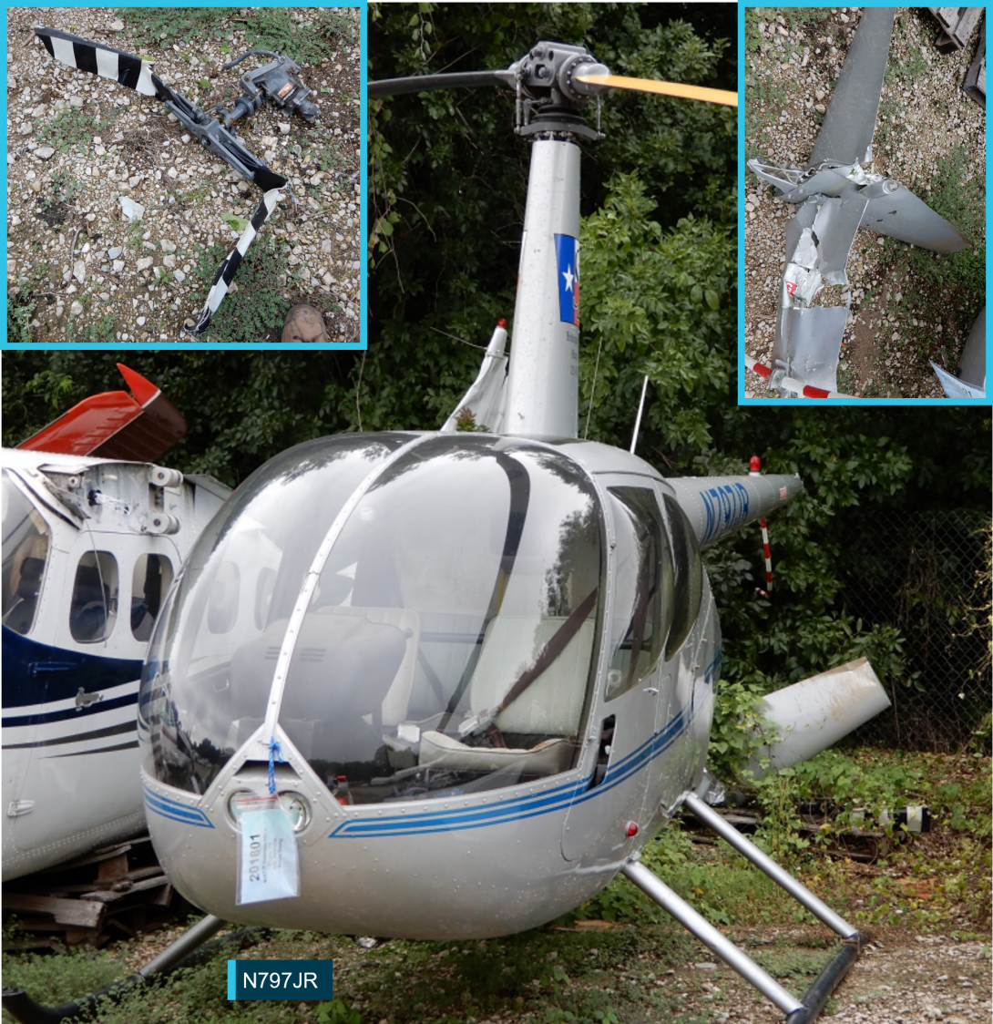
Figure 24 shows R44 N797JR which experienced in-flight break-up similar to VH-NBY while hovering at a height of 50 ft (see the section titled Previous occurrences). The pilot reportedly followed the POH emergency procedure and, even though operating in the ‘avoid’ area of the height/velocity curve chart, the severity of the ground impact was cushioned by the energy remaining in the main rotor system, and the helicopter’s skid gear. There was one person on board who had minor injuries.
Figure 24: N797JR post in-flight break-up
Source: NTSB, annotated by the ATSB
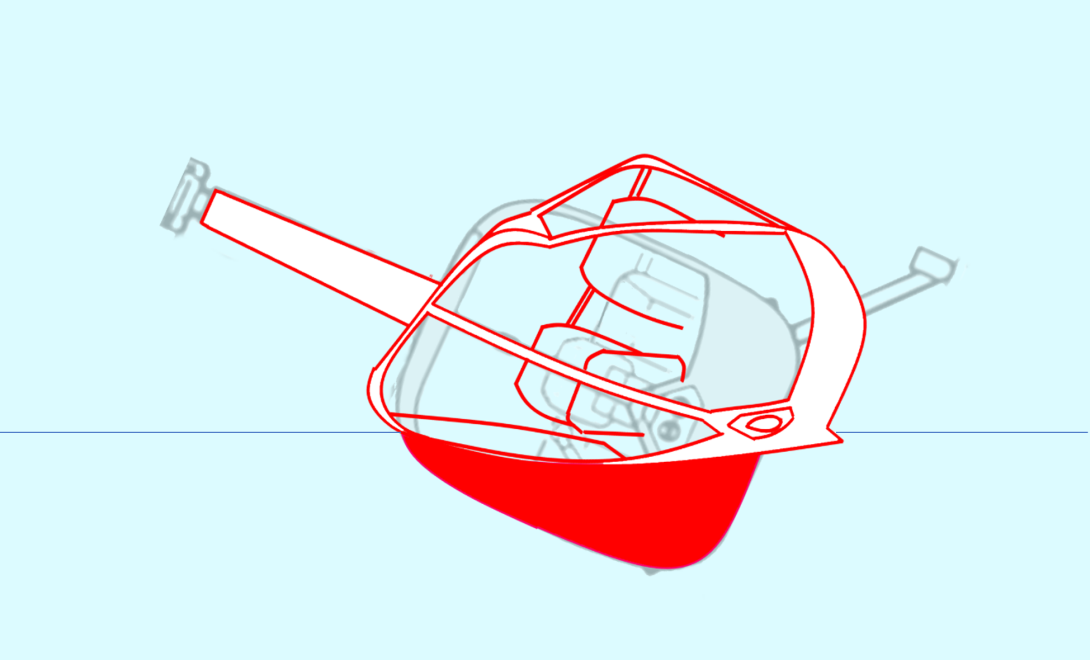
Figure 25 illustrates the deformation in VH-NBY from the side impact. The tail rotor gearbox and empennage fractured from the tail cone at around 55 ft and the helicopter fell from about 75 ft above the ground.
Figure 25: Diagram of cabin deformation in VH-NBY
Source: ATSB
Fuel Tanks
R44 helicopters were originally fitted with aluminium fuel tanks and rigid fuel lines. These fuel tanks and lines were known to rupture on heavy impact. The manufacturer issued a service bulletin (SB78A) to all owners and operators of R44 helicopters to install crash‑resistant fuel bladders by 31 December 2013. The ATSB and CASA separately highlighted the importance of this modification. Today, all R44 helicopters in Australia must be fitted with fuel bladders and flexible fuel lines.
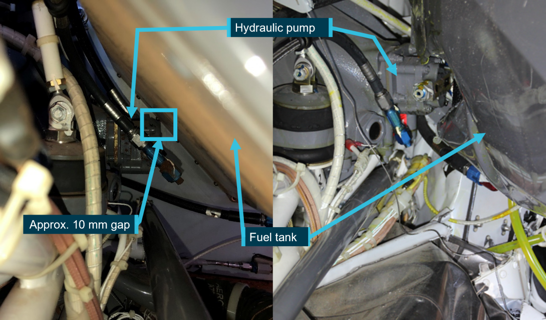
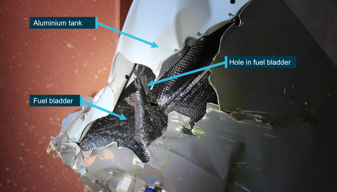
The aluminium skin of the fuel tanks fitted to VH-NBY split at the riveted joints upon impact. The left tank ruptured, but the fuel bladder remained intact, retaining its fuel. The right tank ruptured and the bladder was punctured on impact by the hydraulic pump which was co-located with the main rotor gearbox (Figure 26).
The puncture allowed the release of fuel, but at a low rate (Figure 27). An unknown quantity of fuel leaked from the bladder and attending fire services contained the spill. About 30 L of fuel remained in the helicopter. Given the previously‑observed rupturing of aluminium fuel tanks during significant impact, without the fuel bladders, the risk of a post-crash fire would probably have been significantly higher.
Figure 26: Fuel tank rupture (view forward)
Source: ATSB
Figure 27: Fuel bladder tear
Source: ATSB
Organisational and management information
Registered operator
The owner of VH-NBY was also a director of the registered operator, Avanova Pty Ltd. This company was one of a group of family-owned and related entities. The group consisted of aircraft operators with air operator’s certificates (AOC), and a maintenance organisation that maintained a fleet of float planes. Avanova Pty Ltd did not have an AOC. An associated entity, of which the pilot was also a director, had an AOC for aeroplanes only.
Avanova Pty Ltd was the registered operator of 5 helicopters and 2 aeroplanes at the time of the accident. The helicopters were used for private, business, and commercial purposes for a tourism company. Commercial usage was for tourism charter under third party AOCs.
Private use of the registered operator’s helicopters involved scenic flights, personal transport, and adventure trips. While still classified as private operations, the helicopters were also used in support of the tourism business. They were used to transport workers to remote areas, as well as the conduct of external load work for maintenance and the recovery of company owned‑ vessels.
Approved maintenance organisation
The approved maintenance organisation (AMO) was an authorised Robinson Helicopter service centre. It was a company which provided services to the helicopter industry in the Kimberley region. The AMO’s facilities, located on a station near Broome, were equipped with appropriate tooling for the specific purpose of maintaining and operating Robinson helicopters.
The owner of the AMO was a highly experienced helicopter pilot with around 20,000 hours flight time, mainly in Robinson helicopters. The AMO employed licenced aircraft maintenance engineers and apprentice aircraft maintenance engineers. The AMO had maintained VH-NBY throughout its service history.
VH-NBY operational history
On 29 March 2019, after a period of being operated privately by a different owner, VH-NBY was transferred and registered to Avanova Pty Ltd for tourism work at the Horizontal Falls area in Western Australia. Under a third-party AOC, VH-NBY commenced commercial operations in Western Australia on 13 April 2019 with 60.3 hours from new. On 22 October 2019 it was returned to private use, with Avanova Pty Ltd remaining the registered operator. The company used the helicopter in support of their tourism operations and for personal use.
Operational use of VH-NBY
A potential cause of unusual vibration leading to tail rotor gearbox input cartridge overstress failure was prior damage or stress to the tail rotor. While no evidence of a pre‑existing defect (including fatigue damage) was identified in any of the tail rotor components, given the potential for a previous loading event to have created invisible damage, the ATSB reviewed the prior usage of VH-NBY for events that may have overstressed critical tail rotor components.
Examples of usage with the potential to damage the helicopter were identified, specifically previous instances of:
- excessive manoeuvring
- flight in the obstacle environment
- loss of control near the ground.
The R44 Raven I POH carried advice on excessive manoeuvring. In the safety tips and notices section it stated:
6. Avoid abrupt control inputs or accelerated manoeuvres, particularly at high speed. These produce high fatigue loads and, over time, could lead to failure of a critical component.
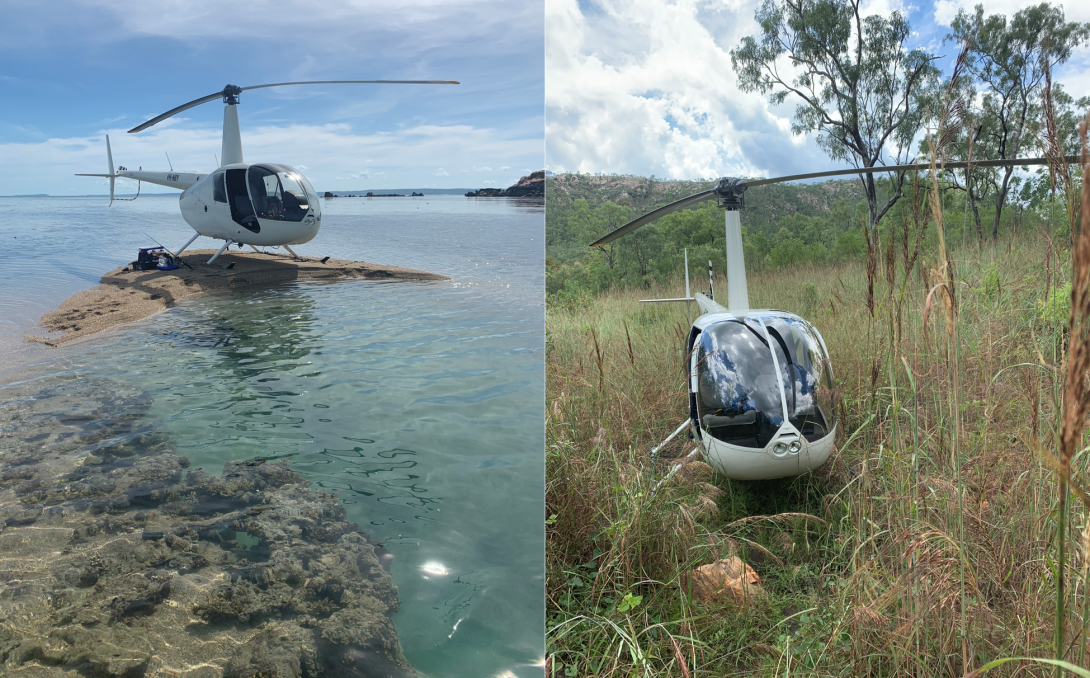
The risk of a rotor or wildlife strike increases the lower an aircraft flies. Additionally, operation close to water and foliage also presents opportunity for unidentified damage (Figure 28). The helicopter’s manufacturer advised that contact with objects such as clothing, water or foliage may cause damage without marking the tail rotor. While examples were found of operation that had the potential to damage the helicopter, no specific evidence was identified.
Figure 28: VH-NBY landing sites
Source: Western Australia Police
Imposition of risk
Intentional non-compliance during previous operation of VH-NBY, and the carriage of passengers on the first flight following ground assessment of the observed vibration prompted an examination of the owner’s risk appetite, and their willingness to expose third parties to risk. For example, the flight conducted on 2 July 2020 was a passenger flight over water following advice of an unusual vibration in the pedals. That flight carried risk of worsening of a condition or failure of a component, without any option to quickly land.
Further examples of imposing risk on third parties without mitigation of that risk were readily found. These activities included:
- exceedance of maximum passengers
- carriage of unrestrained passengers
- external carriage of passengers
- landing in uncontrolled public spaces
- unapproved low flying with passengers
These activities, several of which were witnessed by other parties, carried significant risk, yet there was no evidence that any action was taken to prevent or report them.
The ATSB has a confidential reporting system (REPCON) that enables the identification of unsafe behaviours without jeopardy.
Regulatory oversight of private operations
In line with the Civil Aviation Act (1988) and within the resources available to the Civil Aviation Safety Authority (CASA), CASA oversighted authorisation holders, such as pilots, engineers, and commercial AOC holders. For authorisation holders, CASA had three types of surveillance; planned, sector campaign, and response.
Planned surveillance was conducted under the National Surveillance Selection Process (NSSP). CASA prioritised high volumes of fare paying passengers in their oversight of over 2,000 authorisation holders. In line with CASA’s remit, they did not include private pilots in the NSSP.
Sector campaigns looked at specific industry sectors, such as airline heavy maintenance, or air ambulance services. These sector campaigns were conducted with similar priorities of public benefit and addressed the risks specific to specialised groups. Private pilots would not be expected to feature in these programs.
Private pilots were most likely to be subject to oversight in response surveillance. Response surveillance could be triggered by an incident, observation, or a report to CASA about unsafe behaviour or unsafe condition of aircraft.
Management of airworthiness
In 2005 CASA published a document titled ‘maintenance guide for owners/operators’.[19] This publication was revised in 2012 and updated in 2019. It covered the responsibilities of registered owner/operators and stated:
As a registered owner/operator, you are responsible for the continuing airworthiness of your aircraft. This responsibility begins and ends with you.
To assist registered operators, CASA published regulations, advisory publications, and plain language guides. All the information a registered operator needed to manage the airworthiness of their aircraft was published and freely available from CASA’s website.
Related occurrences
Registered operator’s helicopters
When investigating potential opportunities for previous damage to VH-NBY it became apparent that there was a history of unreported accidents and incidents within the registered operator’s Robinson R44 fleet (Table 4). These included tail rotor strikes and total loss of a helicopter resulting in serious injury.
In order to facilitate safety learning from the latter occurrence, detail is included in Appendix A. The loss of another helicopter (collision with water), which occurred in commercial operations was reported by a third party and investigated by the ATSB (see AO‑2017‑047).
Table 4: Unreported accidents and incidents in registered operator’s R44 fleet
| Helicopter | Occurrence | Location | Date |
| VH-SCM | Tail rotor strike | Broome, WA. | September 2016 |
| VH-ZGY | Tail rotor strike | Horizontal Waterfalls, WA | August 2017 |
| VH-ZGY | Collision with water | Raft Point, WA | July 2019 |
| VH-NBY | Bird strike | Broome, WA | August 2019 |
| VH-TUY | Main rotor strike | Unknown | November 2019 |
| VH-NBY | Loss of control | Cyclone Creek | March 2020 |
VH-NBY, Main rotor bird strike, near Broome, WA. 25 August 2019
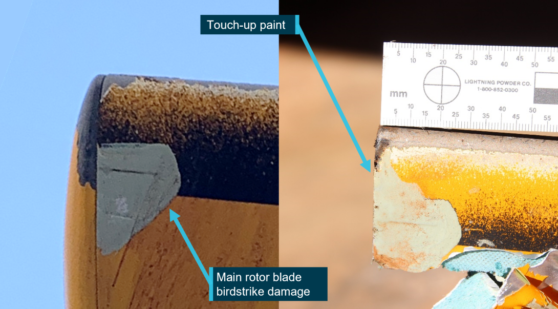
During cruise, the helicopter’s main rotor blade struck a bird. The species was brown booby, a large bird with weight up to 1.4 kg and wingspan up to 1.4 m. The surface of one main rotor blade tip was damaged (Figure 29).
The main rotor blade tip was painted at some point after this event. There is no mention of inspection or repair in any of the helicopter logbooks or maintenance releases.
Figure 29: Damage to VH-NBY main rotor following bird strike, and blade at accident site
Source: Western Australia Police, annotated by the ATSB
VH-NBY, loss of control while landing on a vessel, near Cyclone Creek, WA. March 2020
VH-NBY was used in support of recovery of the domestic commercial vessel Jetwave Pearl which had capsized in a storm at Cyclone Creek.
While landing on the vessel Kimberly Quest 2, the skid gear caught the edge of the rubber matting on the helipad. This led to loss of control, the helicopter pitched forward and right before control was recovered. The matting on the deck of the vessel was torn.
It is not known if any tail strike or damage to VH-NBY occurred during this event and the captain of the Kimberley Quest 2 reported that no such incident occurred.
Safety analysis
Introduction
Two pilots detected the existence of an unusual vibration in the tail rotor pedals of R44 VH-NBY. The vibration was referred to an approved maintenance organisation (AMO) which completed troubleshooting involving ground running of the helicopter with no defect identified. Subsequently on the following flight with the pilot and 3 passengers, major sections of the tail that included the empennage and tail rotor gearbox (TRGB) fractured and then separated from the helicopter in-flight. Control of the helicopter was lost, resulting in fatal injuries to the pilot and one of the passengers and serious injuries to the remaining 2 passengers.
In that context, this safety analysis will examine the nature of the defect and the factors that led to it resulting in a fatal accident.
In-flight break-up
Examination of the aircraft and components found that the TRGB was functioning correctly, the TRGB input cartridge was manufactured to design specification, and the helicopter design was certified under the United States 14 Code of Federal Regulations (CFR) Part 27. All attaching hardware from the tail rotor system was present, and there was no evidence of incorrect assembly.
No components showed evidence of continual abnormal operation, or damage such as pre‑existing fatigue cracking.
Break-up sequence
The in-flight break-up of the tail rotor components was a rapid and complex sequence of events. A review of the recorded closed-circuit television (CCTV) and analysis of the physical evidence (tail rotor and empennage components) determined the following likely sequence:
- it is likely that the in-flight break-up began at the bolted connection between the TRGB and the aft tail cone bulkhead
- dynamic loads during take-off overstressed the attachment lugs of the input cartridge to the TRGB
- the attachment bolts and threaded inserts that secured the lugs of the input cartridge were also pulled at about that moment, shearing the internal threads from within the cast alloy bulkhead
- the TRGB dislodged, moving rearward and down
- the trailing edge of the lower vertical stabiliser was struck by a tail rotor blade. The other tail rotor blade impacted the underside of the tail cone
- the resultant shock loading through the stabiliser from the rotor blade impact fractured the cast bulkhead
- the stabiliser and gearbox both separated from the tail cone
- due to the bending applied from the now out of position gearbox, the bolted interconnection between the rear flex plate, drive shaft and tail rotor input yoke was compromised
- impact damage from the flailing driveshaft led to further break-up of the remnant section of bulkhead casting and aft end of the tail cone.
Source of vibration
Vibration in a helicopter can come from a multitude of sources. Tail rotor imbalance, a common source of vibration in pedals, was found to be within limits by the attending engineers the day before the accident. It was therefore considered to be an unlikely source of the vibration felt by the pilots of VH‑NBY. The minor fretting identified in the attaching hardware of the TRGB input cartridge (Figure 17) was indicative of movement with the potential to have increased vibration in the tail rotor system.
Main rotor vibrations ordinarily present as a bounce or lateral shimmy felt through the pilots’ seat, and there were no reported faults with main rotor track or balance. The main rotor drive train displayed no pre-accident damage, and cyclic, collective, and throttle control systems were found to be continuous and displayed no pre-accident damage.
A disturbance in the engine can cause fluctuations of power and therefore change thrust from the tail rotor, which can present as ‘kicks’ in the yaw plane. An engine cylinder change had occurred 4 flight hours earlier, and the helicopter had been test flown with no fault found. Additionally, there were no reported concerns with the engine from the pilots or engineers. The engine was producing power and was stated to sound normal on the day of the accident. Additionally, CCTV analysis showed rotor rpm to be within its normal range.
Tail rotor drive train disturbances were also considered unlikely, as examination of the tail rotor drive train and TRGB found no pre-existing faults.
If an undetected problem existed in any of the above systems, it could not be ruled out, nor linked with certainty to a characteristic vibration that would manifest as tapping in the pedals. Therefore, it was not possible to identify the source of the vibration.
The precursor to this in-flight break-up echoes the pilot’s operating handbook (POH) warning of a change in sound or vibration forewarning of a potential failure of a critical component. In other similar in-flight break-ups, the pilots also reported vibration in the pedals, which have a direct linkage through the control rods and bell cranks to the tail rotor system, prior to component failure.
While the association cannot be made beyond doubt, the reported vibration in the pedals is likely to have been associated with the developing sequence that ultimately led to in‑flight failure of the tail section.
Input cartridge failure
The input cartridge was examined in detail alongside several other input cartridges from other helicopters. The component was found to be made of the correct material and to the approved design. There was no evidence of manufacturing defects that predisposed the input cartridge to prematurely fail. The lug fracture surfaces contained only evidence of overstress, with no indications of pre-existing damage such as fatigue.
There was no evidence of incorrect assembly. The fasteners were all accounted for, and the mating surfaces of the attachment lugs showed accident damage. There were signs of micromovement on one attachment bolt. This suggests that the input cartridge may have moved under load in service and could have been the source of tapping reported in the pedals.
There were no pre-existing abnormalities to the TRGB, nor pre-existing damage to the tail rotor blades that might otherwise explain the source of the extreme loading. The manufacturer advised that it is possible to impart unusual load on a tail rotor system without permanently marking the tail rotor. While opportunity for that to have occurred existed, there was no evidence of any such contact prior to this event. Additionally, witnesses on the day of the accident stated that they did not see any foreign objects contact the tail rotor.
In summary, the source of any potential initiator of the vibration or overstress of the lugs that precipitated the in-flight break-up of the tail section components could not be determined.
Fuel bladders
While the skin of the aluminium tanks had ruptured, the fuel bladders in the tanks retained most of the fuel during the event. A tear in the left bladder made by the hydraulic pump leaked fuel at a rate low enough to significantly reduce the risk of a post-impact fire.
Response to the identified vibration
The tail rotor pedal vibration was first identified during the short flight from the industrial property to Broome Airport. Although the pilot reported it to the owner, it was not annotated as a defect on the maintenance release (MR) and no engineering examination of the helicopter was conducted prior to the return flight.
The vibration was reported to have been light at that stage and thought to be related to paint on the tail rotor, its implication therefore may not have been recognised. However, examination of the helicopter at Broome Airport would have permitted a maintenance check flight to have been conducted in an open area. Compared to the industrial helicopter landing site, this would have offered a safer response in the event of a worsening condition or failure. It also offered the advantage of on-site emergency services.
Following the return flight to the industrial property and having had the opportunity to personally assess the vibration, the owner arranged for examination by maintenance personnel. Again, the defect was not annotated on the MR, although the vibration was conveyed to the maintenance organisation.
In addition to not annotating any defect in Part 2 of the MR, the ATSB identified that the MR had not been correctly used to record the operation of the helicopter for the 4 weeks preceding the accident. While this may have been influenced by the small number of pilots using the helicopter and verbal communication of the tail rotor vibration, it bypassed a vital tool for recording and communicating the airworthiness of the helicopter.
Due to an assessment by the pilot associated with the maintenance organisation that a check flight could not be safely conducted at the industrial property, evaluation of the reported vibration was confined to a ground run of VH‑NBY, with no defect identified. There were varying accounts of what follow‑up troubleshooting was required. As annotated in their maintenance documentation, the maintenance personnel reported that the owner was advised that a check flight should be conducted. However, the pilot that first detected the vibration and the accident pilot were reportedly unaware that a check flight was required. Again, no related entry was made on the MR, removing an opportunity to clearly detail any required actions.
Understanding defect resolution processes is vital for registered operators to manage the airworthiness of their aircraft. The process includes an iterative cycle of fault finding and critical analysis of every step until the reasons for the defect have been identified and rectified. In this case, and irrespective of the understanding relating to the need for a follow‑up check flight, as the vibration was reported during flight, and no defect was identified, or significant corrective action undertaken, following the ground‑based maintenance assessment, it is reasonable to have concluded that the problem may still be present.
In that context, the safest next step was the conduct of a graduated flight check (the stated preference of the attending engineer and consistent with the advice of the helicopter manufacturer) by a solo pilot. By contrast, the next and final flight was conducted with 3 passengers and involved a steep, high-power departure, possibly following a brief pause in the hover. The unnecessary carriage of passengers resulted in a significantly more severe outcome following the in‑flight break‑up.
The pilot’s decision to conduct the flight in this manner may have been influenced by a belief that the vibration was a minor issue associated with excess paint on the tail rotor blades. However, there was also evidence that the pilot was willing to take, and expose others to, elevated risk. Specifically, despite being important safety defences, the pilot did not have a current aviation medical certificate or R44 helicopter flight review at the time of the accident.
Additionally, during a review of the past usage of VH-NBY to identify any previous events that may have damaged the tail rotor, numerous instances of high risk operation by the accident pilot were identified (together with several reportable matters that had not been conveyed to the ATSB). These included the conduct of low flying and external load operations without the required training or qualifications and, more significantly, the carriage of passengers in an unsafe manner on multiple occasions.
The ATSB concluded that the pilot’s high-risk appetite may have influenced the way the accident flight was conducted. It may also have made the pilot less likely to heed the warning in the R44 POH regarding the significant implication of a change in sound or vibration of the helicopter. Finally, while there was no evidence that the identified reportable matters contributed to this accident, the notification of occurrences to the ATSB is an important component of the aviation safety system.
Departure and emergency response
In other similar tail rotor failure occurrences, use of the POH emergency procedure resulted in a safe outcome for the occupants. One of the similar occurrences involving N797JR, happened in a high hover, similar to VH-NBY, though VH-NBY was likely heavier at the time.
The confined area associated with the industrial property required the pilot of VH-NBY to conduct a near-vertical departure, within the avoid area of the height / velocity diagram, limiting the energy available in the helicopter to use in an emergency response. That departure also demanded higher power than the recommended take-off profile over open ground. With the higher power was an associated higher torque, which sought to rotate the cabin of the helicopter to the right with more force. That in turn required higher counteracting thrust from the tail rotor.
CCTV showed that after the initial break-up VH-NBY continued climbing and rotating. The flight manual procedure of lowering the collective and/or closing the throttle would have seen rotation stop or slow, and VH-NBY would have descended. Use of that procedure while the aircraft was still oriented upright would have exposed the skid gear to contact with the ground first, and absorbed the impact energy, improving survivability.
Impairment and response times
Pilot intervention time is an important factor in recovery from an emergency, and unless primed, the stress of an emergency can impair response times. Startle is a stress response to a sudden intense event. It can cause involuntary reflex and cognitive impairment and can last from 0.3 seconds at the low end, to 1.5 seconds for a high intensity response (Rivera and others 2014).
The United Kingdom Civil Aviation Authority (CAA) published a paper on Helicopter Tail Rotor Failures in 2003. The purpose of the paper was to examine tail rotor failures and explore potential mitigators to reduce the incidence and consequences of tail rotor failures. The report related that pilot intervention time is highly variable. The CAA determined an intervention time of 2 seconds was a realistic average to use for their simulator trials.
CCTV analysis showed an approximate 2.7 seconds from contact of the tail rotor blade with the lower vertical fin, to the end of the first rotation. In the case of VH-NBY, the forces in the first rotation would have been roughly equivalent to 2.6 g. The forces in the second rotation would have climbed too high for a pilot to manipulate the controls. As such, the end of the first rotation was probably the last opportunity to prevent the total loss of control. Any impairment greater than 0.7 seconds could have prevented initiation of recovery actions in time to prevent loss of control.
Training and checking of private pilots
Once licenced, private pilots can fly with very little further training and supervision. The regulations require private pilots to demonstrate competence through a helicopter flight review (HFR) every 2 years. Yet over time, a pilot’s skills and knowledge can degrade. The owner of VH-NBY had not demonstrated competence in an R44 for about 2 years and 8 months and had completed a flight review in a Bell 505 within 2 year and 2 months. The emergency procedure for tail rotor failure is similar between the R44 and Bell 505.
A pilot cannot be reasonably expected to maintain competence in emergencies without deliberately exercising their skills and knowledge, supported by independent assessment of their abilities. CASA advises pilots that the two-year cycle of flight reviews does not guarantee safety. Consequently, they encourage pilots to assess their risk profile and seek opportunities to develop their skills, utilising for example training and checking with an experienced instructor.
Findings
|
ATSB investigation report findings focus on safety factors (that is, events and conditions that increase risk). Safety factors include ‘contributing factors’ and ‘other factors that increased risk’ (that is, factors that did not meet the definition of a contributing factor for this occurrence but were still considered important to include in the report for the purpose of increasing awareness and enhancing safety). In addition ‘other findings’ may be included to provide important information about topics other than safety factors. Safety issues are highlighted in bold to emphasise their importance. A safety issue is a safety factor that (a) can reasonably be regarded as having the potential to adversely affect the safety of future operations, and (b) is a characteristic of an organisation or a system, rather than a characteristic of a specific individual, or characteristic of an operating environment at a specific point in time. These findings should not be read as apportioning blame or liability to any particular organisation or individual. |
From the evidence available, the following findings are made with respect to the in-flight break-up of Robinson Helicopter Company R44 Raven I serial number 2544 registered as VH-NBY on 4 July 2020, 3 km north of Broome Airport, Western Australia.
Contributing factors
- Following a period of pedal vibration over at least 2 flights, overstress fracture of the attachment lugs of the tail rotor gearbox input cartridge occurred. The source of the loading that led to the overstress fracture was not conclusively determined.
- Two pilots experienced vibration through the helicopter’s tail rotor pedals on separate flights and did not endorse the problem on VH-NBY’s maintenance release. Additionally, following tail rotor inspection and vibration analysis on the ground, the engineers did not endorse the requirement for a maintenance check flight on the maintenance release. As a result, the value of the maintenance release as a tool for communication and management of airworthiness was lost.
- A recommendation in the R44 pilot's operating handbook was not followed. It advised pilots that following detection and inspection of an unusual vibration, they should hover the helicopter then have it reinspected before resuming free flight.
- The pilot conducted a towering high-power take-off in VH-NBY from a confined area with 3 passengers on board. The unnecessary carriage of passengers resulted in a significantly more severe outcome following the inflight breakup.
- Shortly after take-off, following the overstress fracture of the attachment lugs, the tail rotor gearbox separated from the helicopter. This led to fracture of the aft tail cone bulkhead and separation of all components attached to it, including the horizontal and vertical stabilisers.
- With limited time and the stress associated with the emergency event, the pilot did not apply the pilot’s operating handbook procedure for responding to a tail rotor emergency. Prompt application of the procedure would have reduced the likelihood of loss of control, and therefore improved the potential for survivability.
Other factors that increased risk
- The pilot did not have a valid flight review for the R44 helicopter type or a current medical certificate. The former increased the risk of an inappropriate response to the tail rotor emergency and the pilot was not legally authorised to operate an R44 helicopter at the time of the accident.
- The owner of VH-NBY demonstrated acts of non-compliance with multiple aviation safety regulations. Additionally, VH-NBY was operated in a manner that increased the risk of damage or stress to the helicopter on multiple occasions. These actions had an adverse influence on safety and imposed unnecessary risk on passengers and third parties.
- Although the registered operator of VH-NBY was responsible for the continued airworthiness of its helicopter fleet, they did not employ a conservative defect resolution process that would have supported further trouble shooting.
Other findings
- The attending engineers found that visual inspection of the tail rotor system and associated components, running the helicopter on the ground, and dynamic tail rotor balancing, could not replicate the stated problem. It is likely that the vibration only presented in powered flight.
- There was a history of unreported accidents and incidents with the registered operator of VH‑NBY's aircraft, in both commercial and private operations. These occurrences included 2 tail rotor strikes in different R44 helicopters, and a total hull loss of another R44 helicopter (VH‑ZGY) that resulted in serious injuries to a passenger.
- Although a fuel bladder was punctured during the accident sequence, and fuel was lost from the tanks, the fuel bladders reduced the flow rate of escaping fuel, which reduced the risk of a post-crash fire.
Glossary
AAIB Air Accidents Investigation Branch (United Kingdom)
ALARP As Low As Reasonably Practical
AOC Air Operator’s Certificate
AME Aviation Maintenance Engineer
AMO Approved Maintenance Organisation
CASA Civil Aviation Safety Authority
EDS Energy Dispersive x-ray Spectrometer
FAA Federal Aviation Administration (United States of America)
HAAMC Head of Airworthiness and Maintenance Control
HFR Helicopter Flight Review
LAME Licenced Aviation Maintenance Engineer
MR Maintenance Release
NTSB National Transportation Safety Board (United States of America)
POH Pilot’s Operating Handbook
PPL Private Pilot’s Licence
RHC Robinson Helicopter Company
SEM Scanning Electron Microscope
SES State Emergency Service
TRGB Tail Rotor Gearbox
TR Tail Rotor
VFR Visual Flight Rules
Sources and submissions
Sources of information
The sources of information during the investigation included the:
- pilots of VH-NBY
- maintenance organisations for VH-NBY
- commercial operators of the registered operator’s aircraft
- next of Kin
- flight schools attended by the pilot
- Civil Aviation Safety Authority
- United States National Transportation Safety Board
- United Kingdom Air Accidents Investigation Branch
- Aviation Safety Network
- Western Australia Police Force
- Robinson Helicopter Company
- Airservices Australia
- witnesses
- video footage of the accident flight and other photographs and videos of company aircraft
- recorded data from the aircraft tracking unit on the helicopter
References
Australian Transport Safety Bureau, AR-2020-014, Aviation Occurrence Statistics 2010 to 2019, 2020, Canberra.
American Society for Metals International, 2004, ASM Handbook, Volume 9: Metallography and Microstructures, Materials Park, Ohio.
American Society for Metals International, 2021, ASM Handbook, Volume 11 Failure Analysis and Prevention, Materials Park, Ohio
Casner SM, Geven RW & Williams RT, ‘The effectiveness of airline pilot training for abnormal events’, Human Factors: The Journal of the Human Factors and Ergonomics Society, 2013 vol. 55, pp.477-485.
Civil Aviation Authority United Kingdom, CAA Paper 2003/1, Helicopter Tail Rotor Failures 2003.
Dismukes RK, Berman BA & Loukopoulos LD, The limits of expertise: Rethinking pilot error and the causes of airline accidents, 2007, Ashgate Aldershot UK.
Flight Safety Foundation, Simulator-based study of Emergencies Yields Insights into Pilot’s Reaction Times, March-April 1999, Vol. 25, No. 2, Alexandria, VA.
Glendon AI, Mckenna EF, Human safety and risk management, 1995, Chapman & Hall, London
Greening L, Chandler CC, Why It Can’t Happen to Me: The Base Rate Matters, But Overestimating Skill Leads to Underestimating Risk, Journal of Applied Psychology, 1997, 27:9, 760-780.
Hudson, P, Safety culture: The ultimate goal, Flight Safety Australia, September-October 2001 Civil Aviation Safety Authority, Canberra.
Hunter DR, Risk Perception and Risk Tolerance in Aircraft Pilots, Federal Aviation Administration, DOT/FAA/AM-02/17, 2002.
Klein G, Sources of power: How people make decisions, Massachusetts Institute of Technology 1998.
Landman A, Groen EL, van Passen VV, Bronkhorst AW & Mulder M, ‘The influence of surprise on upset recovery performance in airline pilots,’ The International Journal of Aviation Psychology, 2017 vol. 27, pp.2–14.
Lawton R, Not working to rule: Understanding procedural violations at work, Safety Science, 1998, 28:2, 77-95.
Rivera, J., Talone, A.B., Boesser, C.T., Jentsch, F. and Yeh, M., Startle and surprise on the flight deck: Similarities, differences, and prevalence. In Proceedings of the human factors and ergonomics society annual meeting September 2014 (Vol. 58, No. 1, pp. 1047-1051). Sage CA: Los Angeles, CA: SAGE Publications.
Yates JF (ed), Risk-taking behavior, 1992, John Wiley & Sons, New York, NY.
Zinn, JO. The meaning of risk-taking – key concepts and dimensions, Journal of Risk Research, 2019, 22:1, 1-15.
Submissions
Under section 26 of the Transport Safety Investigation Act 2003, the ATSB may provide a draft report, on a confidential basis, to any person whom the ATSB considers appropriate. That section allows a person receiving a draft report to make submissions to the ATSB about the draft report.
A draft of this report was provided to the following directly involved parties:
- the registered operator of VH-NBY
- Civil Aviation Safety Authority
- maintenance organisation for VH-NBY
- Robinson Helicopter Company
Submissions were received from the registered operator of VH-NBY and the Robinson Helicopter Company. The submissions were reviewed and, where considered appropriate, the text of the report was amended accordingly.
Appendices
Appendix A – VH-ZGY collision with water
What happened
On 12 July 2019, a private vessel, High Calibre, had repositioned to Raft Point, Western Australia (Figure 30). A Robinson R44 Clipper II, serial number:12491 registered as VH-ZGY was parked on the helipad of the vessel (Figure 31). There were 4 people aboard High Calibre, the owner of the vessel (and helicopter), and 3 individuals. The weather was fine and the water in the bay was calm.
Figure 30: Occurrence location
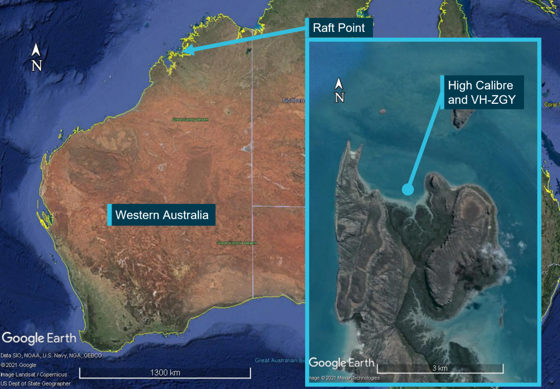
Source: Google Earth annotated by ATSB
It was reported to the ATSB that 2 people required transfer to another helicopter (VH-NBY) located nearby on-shore, to return to Broome. A witness stated that VH-ZGY had been used twice already that day and had landed to load a third passenger without shutting down. Simultaneously, friends and family of the vessel’s owner were due to arrive at Raft Point via seaplane to holiday aboard High Calibre. It was reported that the transfer to VH-NBY in VH-ZGY needed to be completed in time for the owner to get back to High Calibre and meet their guests.
The owner of the helicopter was piloting the helicopter and sat front right. One passenger sat front left, and the second passenger sat rear right. It was reported that upon take off the helicopter yawed left and then tipped forwards and rolled to the right. The main rotor blades contacted the starboard side of the vessel (Figure 32). The helicopter then collided with water and sank.
While it was reported to the ATSB that a tie-down was still attached under the nose of the helicopter and that initiated the roll over, another witness stated that all tie downs had been removed and stowed. They added that access to the helicopter meant climbing a ladder which put the pilot and passengers at eye level with the deck. Allowing them to check for tie-downs as they climbed.
It is possible that control was lost due to the helicopter remaining tethered. Alternatively, if it had recently landed and was untethered, a mishandled departure may have initiated the roll over. The helicopter was not inspected and the actual cause of the rollover was not determined.
Figure 31: VH-ZGY on High Calibre
Source: Western Australia Police Force annotated by ATSB
Figure 32: Damage to High Calibre
Source: Western Australia Police Force, annotated by the ATSB
Under section 18 of the Transport Safety Investigation Act 2003 a responsible person with knowledge of an immediately reportable matter must report it. The loss of VH-ZGY was not reported to the ATSB.
Safety action
It is not known whether the registered operator took safety action as a result of this event.
Safety message
In 2016 the Federal Aviation Administration in the US released a safety alert SAFO16016. This alert advised pilots of the importance of utilising checklists and performing stabilised hover checks. This allows pilots to ensure vital actions have been performed before departure and allows a pilot to abort a take-off if anything is not right or discovered amiss. While SAFO16016 may require adjustment to suit waterborne operations the principals apply.
The reporting of accidents and incidents is vital for the sharing of lessons learnt that may be implemented by industry, reducing the risk of future accidents and incidents. Additionally, the data the ATSB and other agencies collect through reporting is deidentified and used in Australia and worldwide for analysis of factors impacting aviation safety to improve outcomes for all users of aviation services of all types.
Organisations and individuals that report accidents and incidents contribute to the growth towards a generative safety culture[20] in Australia and around the world. Those organisations and individuals are more able to generate safe outcomes in aviation operations as a result.
Occurrence details
| Date and time: | 12 July 2019 |
| Occurrence category: | Accident |
| Primary occurrence type: | Collision with water |
| Location: | Raft Point, Western Australia |
| Latitude: 16º 04.34' S | Longitude: 124º 27.45' E |
Aircraft details
| Manufacturer and model: | Robinson Helicopter Company R44 Clipper II | |
| Type of operation: | Private | |
| Activity: | General Aviation / Recreational | |
| Sector: | Helicopter | |
| Departure: | Raft Point, Western Australia | |
| Destination: | Horizontal Falls, Western Australia | |
| Persons on board: | Crew – 1 | Passengers – 2 |
| Injuries: | Crew – 1 minor | Passengers – 1 serious, 1 minor |
| Aircraft damage: | Destroyed |
Appendix B – Robinson Helicopter ground handling incidents
Introduction
In the course of investigation into the in-flight break-up of VH-NBY. The ATSB received anecdotal evidence of aft tail cone bulkhead castings failing after contact of the horizontal stabiliser with a solid object during ground handling.
While the ATSB welcomes reporting of ground handling incidents, it is not a requirement under the Transport Safety Investigation Regulations to report them. Therefore, the ATSB did not have a suitable record of events to examine.
An update to the investigation was published on 17 August 2021. In that update the ATSB sought information from operators who had experienced ground handling issues. Specifically resulting in damage to the aft tail cone bulkhead and tail rotor gearbox input cartridge.
Response from industry
The ATSB is grateful to the large number of members of the helicopter industry in Australia and overseas who provided valuable insight, experience, information, and components to the ATSB. This knowledge and material was analysed in the context of the failure of VH-NBY and supported the investigative process.
Three casting fractures were identified one in each of R22, R44 (Figure 33) and R66. Each was the result of contact of the horizontal stabiliser with a fixed object while ground handling the helicopter.
Figure 33: Ground handling damage to an R44
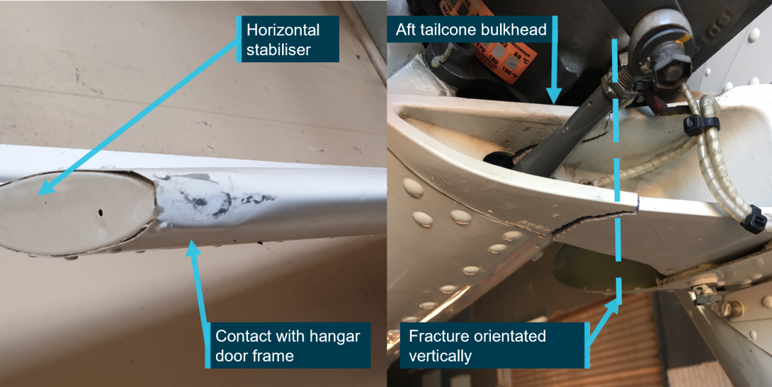
Source: Supplied
These failures were a known issue and the manufacturer had published service letters for each type on 11 March 2020.
- R22 service letter SL-86
- R44 service letter SL-72
- R66 service letter SL-33
With the support of R44 owners and operators, the ATSB was able to analyse these materials and rule this out as a mechanism of failure for VH-NBY.
Purpose of safety investigationsThe objective of a safety investigation is to enhance transport safety. This is done through:
It is not a function of the ATSB to apportion blame or provide a means for determining liability. At the same time, an investigation report must include factual material of sufficient weight to support the analysis and findings. At all times the ATSB endeavours to balance the use of material that could imply adverse comment with the need to properly explain what happened, and why, in a fair and unbiased manner. The ATSB does not investigate for the purpose of taking administrative, regulatory or criminal action. TerminologyAn explanation of terminology used in ATSB investigation reports is available here. This includes terms such as occurrence, contributing factor, other factor that increased risk, and safety issue. Publishing informationReleased in accordance with section 25 of the Transport Safety Investigation Act 2003 Published by: Australian Transport Safety Bureau © Commonwealth of Australia 2023
Ownership of intellectual property rights in this publication Unless otherwise noted, copyright (and any other intellectual property rights, if any) in this report publication is owned by the Commonwealth of Australia. Creative Commons licence With the exception of the Coat of Arms, ATSB logo, and photos and graphics in which a third party holds copyright, this publication is licensed under a Creative Commons Attribution 3.0 Australia licence. Creative Commons Attribution 3.0 Australia Licence is a standard form licence agreement that allows you to copy, distribute, transmit and adapt this publication provided that you attribute the work. The ATSB’s preference is that you attribute this publication (and any material sourced from it) using the following wording: Source: Australian Transport Safety Bureau Copyright in material obtained from other agencies, private individuals or organisations, belongs to those agencies, individuals or organisations. Where you wish to use their material, you will need to contact them directly. |
[1] Refinishing the painted tips of Robinson Helicopter tail rotor blades is common practice in Australia, as sand and dust erodes tail rotor blades, potentially reducing their useful life.
[2] Tail skid: A guard device below the empennage to protect the tail rotor blades from ground strike.
[3] Interpretation of Measured Alcohol Levels in Fatal Aviation Accident Victims: Interpretation of Measured Alcohol Levels | ATSB
[4] CASA 007/17 was superseded by CASA 62/20, and the requirement remained.
[5] The tail rotor blade life limit is 2,200 hours of operation or 12 years, whichever occurs first.
[6] Qualified person: a suitably licenced aviation maintenance engineer or pilot endorsed and current on the aircraft type.
[7] Basic HLS: a place that may be used as an aerodrome for infrequent, opportunity and short term basis for all types of operations, other than RPT, by day under helicopter VMC.
[8] CASA CAAP 92-2(2) Guidelines for the establishment and operation of onshore Helicopter Landing Sites.
[9] Threaded inserts: Robinson Helicopter Company manufacturing required threaded inserts to be fitted at each of the bolt holes in the casting, to secure the bolts.
[10] Cleavage facets: Bright reflective facets remaining following cleavage fracture
[11] Shrinkage pores: Cavities formed in the metal casting process
[12] Micro dendritic defects: A crystal with a treelike branching pattern. It is most evident in cast metals slowly cooled through the solidification range.
[13] Beach marks: The most characteristic feature usually found on fatigue-fracture surfaces are beach marks, which are centred around a common point that corresponds to the fatigue-crack origin. Beach marks can occur due to changes in loading or frequency or by oxidation of the fracture surface during periods of crack arrest from intermittent service of the part or component.
[14] Material specifications: US Federal Specification QQ-A-225/9E Aluminium Alloy 7075, Bar, Rod, Wire and Special Shapes; Rolled, Drawn or Cold Finished. 24 August 1971
[15] Attendance at disassembly: Involved parties could not attend in person due to COVID restrictions. A video link, and on‑site photographer were made available to them.
[16] Angular tear ridges: Tearing caused by ductile overstress following plastic deformation.
[17] Ductile morphological features: fracture features that are characterised by tearing of metal and appreciable gross plastic deformation and expenditure of considerable energy. Ductile fractures are those that occur by microvoid formation and coalescence.
[18] 14 CFR Part 27: Airworthiness standards for normal category rotorcraft. Including subparts covering strength requirements and, design and construction.
[19] CASA’s Maintenance guide for owner/operators is available at their online store.
[20] Generative safety culture: This is the highest level of Hudson’s safety culture ladder and is described as safety behaviour being integrated into everything the organisation does.


