
What happened
On 5 February 2018, a Boeing 757 freighter aircraft, registered VH-TCA, operated by Tasman Cargo Airlines Pty. Ltd., departed from Auckland International Airport, New Zealand for Sydney International Airport, Australia.
Passing through an altitude of 6,000 ft, the left hydraulic system quantity warning message displayed. The crew actioned the Quick Reference Handbook (QRH) checklist and obtained clearance from Air Traffic control (ATC) to level out at 8,000 ft, in a holding pattern to the north‑west of Auckland Airport.
Shortly after commencing the holding pattern, the crew received further warning messages regarding both the left and right hydraulic systems. Following the appropriate actions in the QRH checklists, the crew shut down both systems. The crew made a PAN call to ATC with a request for an immediate return to Auckland. The flaps and landing gear were extended using the alternative systems and the aircraft landed without further incident.
What the ATSB found
The ATSB identified that the dual hydraulic failure was the result of a number of sequential failures in the hydraulic system. The initial failure was a ruptured left main landing gear flex hose, which resulted in a loss of the left hydraulic system pressure. Subsequently, the power transfer unit (PTU) pressure switch did not operate as intended, following depletion of the hydraulic fluid from the left system. This resulted in overheating and failure of the right hydraulic system. The pressure switch was the subject of a 2010 non-mandatory service bulletin which, if implemented, would likely have prevented the failure of the right system.
What's been done as a result
Following the occurrence, the operator conducted preventative maintenance on the aircraft, replacing all of the main landing gear flex hoses as well as updating the PTU pressure switch to conform to the published service bulletin. In addition, the operator revised the aircraft maintenance plan to introduce improved inspections and a time‑limited life on the flex hoses.
Safety message
This occurrence highlights that although some service bulletins are not deemed to be safety critical, they can still have an impact on aircraft reliability. While operators are required to implement all airworthiness directives, the ATSB recommended that operators familiarise themselves with non-mandatory service bulletins and consider the potential impacts of delaying implementation.
Boeing recommends that operators perform periodic inspection of hose assemblies paying particular attention to the high-risk areas of the landing gear area, the engine/pylon areas and the tail/empennage area. Hose assemblies can be difficult to inspect in-situ due to access constraints and the limitations of visual inspection of the multi-layered construction of the hose. As a result, some operators have chosen to introduce a hose replacement schedule, based on flight time in service or a calendar period, in addition to periodic in-situ inspections.
Picture of the ruptured hydraulic flex hose
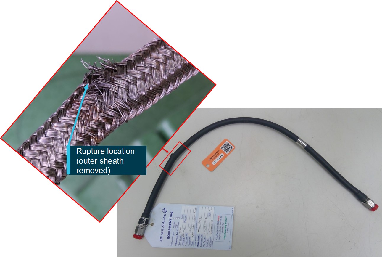
Source: ATSB
On 5 February 2018, at about 0652 Universal Coordinated Time (UTC), a Boeing 757 freighter aircraft, registered VH-TCA, operated by Tasman Cargo Airlines Pty. Ltd., departed from Auckland International Airport, New Zealand for Sydney International Airport, Australia.
Passing through an altitude of 6,000 ft, the flight crew received a left hydraulic quantity warning message. The crew actioned the Quick Reference Handbook (QRH) checklist and obtained clearance from Air Traffic control (ATC) to level out at 8,000 ft, in a holding pattern to the north‑west of Auckland Airport.
Shortly after entering the holding pattern, the left hydraulic system lost pressure as the hydraulic fluid quantity reduced to zero. The crew received a left hydraulic system pressure warning and followed the QRH checklist, which required switching off the left hydraulic engine driven pump and electric pump.
A few minutes later, the crew received a right hydraulic system, engine driven pump overheat message. In response, the crew actioned the QRH and turned off the right engine driven pump. Shortly after, the crew received a right-hand system pressure warning. The crew actioned the corresponding QRH checklist and shut down the right electric motor driven hydraulic pump, resulting in a loss of both the left and right hydraulic systems.
At about 0710, the flight crew declared a PAN[1] and requested both an immediate return to Auckland and for emergency services to be put on standby. The crew received clearance from ATC to commence their approach to runway 23L. The flight crew extended the flaps and landing gear using the alternative systems, and the aircraft touched down at approximately 0735. The flight crew brought the aircraft to a halt at the anticipated location using the manual braking system.
There was no damage to the aircraft and no injuries sustained as a result of the occurrence.
After the occurrence, the operator conducted an examination of the aircraft and discovered that the left main landing gear (MLG) downlock actuator retract flexible (flex) hose was ruptured. No faults were detected during an operational check of the right system and the power transfer unit (PTU) (see the section titled Boeing 757 Hydraulic System). The required components were replaced as per the aircraft maintenance manual (AMM) and the aircraft was returned to service.
In March 2018, following discussion of the occurrence with the aircraft manufacturer, the operator replaced the PTU pressure switch and the right, reservoir standpipe selector valve and sent them to the switch manufacturer for further examination.
__________
Aircraft information
The Boeing 757 aircraft was acquired by the operator in 2013. Before being introduced onto their Air Operator’s Certificate, all maintenance records were uploaded to the maintenance management system and assessed. The audit of the maintenance records was conducted by the operator and was used to verify that all airworthiness directives and mandatory service bulletins (SBs) had been carried out by the previous operator. The records indicated that, although it was not mandated, SB 757-29-0056 (see the section titled Service bulletins) had been incorporated in 2002 to replace the flex line hoses and the PTU pressure switch.
Maintenance and inspection
The flexible hose components were maintained in accordance with the aircraft manufacturer’s requirements and were replaced on-condition[2].
The operator conducted daily inspections on the aircraft. The daily inspection procedures outlined a number of required checks, including a visual inspection of the right and left MLG assembly to check for wear and leaks. Prior to the occurrence flight, there were no defects identified relating to the MLG assembly.
The details of the relevant components installed on the aircraft at the time of the occurrence are listed in Table 1 below.
Table 1: Components installed on VH-TCA on 5 February 2018
| Component | Date / reason replaced | Part Number/ year manufactured |
| Left MLG downlock actuator retract flex hose | Post-June 2016/ unknown | 271N6119-2 / 2011 |
| Right MLG downlock actuator extend flex hose | June 2011 / aircraft configuration change | 271N6119-1 / 2011 |
| February 2018 / ruptured | 271N6119-1 | |
| PTU pressure switch | May 2002 / SB-757-29-0056 | Serial number: Y02905A / 2000 |
Boeing 757 hydraulic system
The aircraft is equipped with three independent hydraulic systems; left, right and centre. The services operated by each system, or combination of systems, are shown in Figure 1. Flight control system components are distributed so that any one hydraulic system can provide adequate aircraft controllability. An additional layer of redundancy is provided such that after a loss of the left and right hydraulic systems, the flaps, slats, landing gear and speedbrakes all have alternative mechanisms for control.
Each of the left and right systems has two pumps, an engine driven pump (EDP), which is the main system pump, and an electric motor driven pump (ACMP). The pumps are supplied with hydraulic fluid from a reservoir, pressurised by the bleed air system. Each of the reservoirs has two supply outlets: one outlet is connected to a standpipe inside the reservoir, to retain reserve fluid at the bottom of the reservoir. The second (reserve outlet) draws fluid from the bottom of the reservoir.
The left system reserve fluid is maintained for use by the power transfer unit (PTU) in the event of a left system hydraulic leak. The right reserve fluid was maintained for use by the reserve brakes in the event of a right system leak.
The ‘standpipe selector valve’ controls which outlet is used. Operation of the right ‘standpipe selector valve’ to the reserve fluid triggers the right ACMP valve to divert the hydraulic pressure to the reserve brakes only.
Power Transfer Unit
The PTU is a hydraulic motor pump which transfers hydraulic power from the right system to the left system (Figure 2). The PTU is automatically activated when the left EDP pressure is low. When activated, the PTU supplemented the left ACMP to operate the following:
- flaps and slats
- landing gear
- nose wheel steering
If the PTU fails to develop pressure in the left system (as expected following the loss of left system fluid), the pressure switch for the PTU senses the lack of system pressure and shuts down the PTU. If the pressure switch is inoperative, the right hydraulic system fluid will begin to heat, as it drives the PTU motor under a no-load condition, due to a lack of left system fluid. Eventually, the right hydraulic system fluid will heat to the point where the temperature switch in the right EDP actuates, causing the right EDP overheat light to illuminate in the flight deck.
Figure 1: The 757 hydraulic system – services controlled by each system
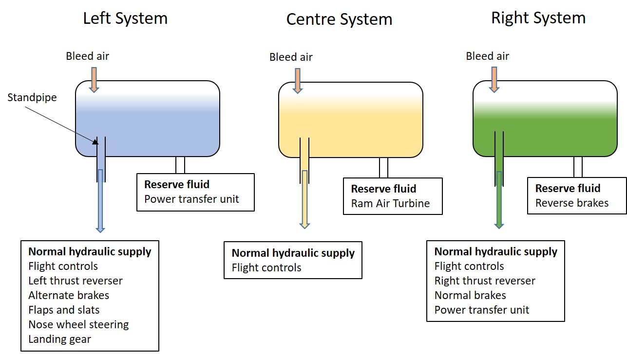
Source: ATSB
Figure 2: The 757 hydraulic system – power transfer unit operation

Source: ATSB
Service bulletins
The following non-mandatory service bulletins were relevant to this occurrence.
2001 – Downlock actuator hose and PTU pressure switch SB 757-29-0056
SB 757-29-0056 recommended the installation of part number (P/N) 271N6119-X downlock actuator hoses and P/N 211C223-521 PTU pressure switches following six reported incidents of dual hydraulic system loss on the Boeing 757. The sequence of events in each case was the depletion of left hydraulic system fluid through a ruptured MLG downlock hose, followed by overheating of the right system. The overheat was due to malfunction of the PTU control pressure switch that allowed the PTU to run continuously in a dry condition.
Boeing Service Letter SL 757-FTD-29-01001 was issued in March 2001 to recommend implementation of the SB at the next convenient maintenance opportunity. This SB was carried out on VH‑TCA prior to the occurrence.
Boeing noted that operators had reported some failures of the P/N 271N6119-X downlock actuator hoses since implementation of this SB.
2010 – PTU pressure switch SB 29-09-05-02
After entering service, the PTU Pressure Switch (P/N 211C223-521) experienced failures due to moisture ingression into the switch. The moisture contamination caused corrosion and leakage paths past the receptacle O-ring seal, which led to erroneous indications and eventual switch failure. The switch supplier issued SB 29-09-05-02 in 2010 to recommend replacement of the receptacle O-ring and application of sealant between the receptacle and housing. Modified switches were marked with the letter ‘C’ at the end of the serial number. The recommended action was to be performed at the next suitable planned maintenance period.
Boeing Service Letter 737-SL-29-069-C was issued to operators in May 2010. The service letter provided background information to SB 29-09-05-02 and a recommendation for either the incorporation of the design changes on an attrition basis or retrofit of the improved pressure switches to affected aircraft in the operator’s fleet. This SB had not been performed on VH‑TCA.
Component examinations
Hydraulic flex hose
The construction of the hydraulic flex hose consists of three layers; an internal rubber tube, housed in a braided metal hose[3] and covered with a rubber sleeve (Figure 3).
The following observations were made during the analysis of the hose assembly:
- the chemical composition of the braid material fell within the required specifications
- the direction of the failed wires indicated that the braided hose failed under burst pressure
- the location of the rupture was not coincident with the maximum bend location on the hose, indicating the failure was not due to bending fatigue
- corrosion was limited to the rupture location, indicating that it was likely the wires corroded after the rupture (Figure 4)
- there was some evidence of ductile overstress on the individual wire filaments, but significant corrosion on the fracture surfaces made determination of the failure mode impossible
- no wear, cuts, abrasion or pinching on any of the layers of the hose was evident
- there was no evidence of manufacturing anomalies or kinking/twisting of the hose to indicate improper installation.
Figure 3: Hydraulic flex hose construction

Source: ATSB
Figure 4: Scanning electron microscope images of the ruptured area on the left hose

Source: Aircraft manufacturer, annotated by the ATSB
PTU pressure switch
The examination of the PTU pressure switch revealed that the electrical switch contacts were stuck in the ‘normally open’ state due to an excessive amount of contamination on and around the electrical switch button. The contamination prevented the switch from returning to the ‘normally closed’ (unpressurised) condition. The visual appearance of the contamination was consistent with corrosion, as identified in the 2010 SB (SB 29-09-05-02).
Visual examination revealed a large amount foreign object debris (FOD) throughout the entire unit. Indications were that the FOD entered the unit past the O-ring seal between the receptacle and the unit housing (Figure 5).
Standpipe valve selector
The right reservoir standpipe selector valve was tested and found to be leaking, but functional. The teardown analysis revealed that the electrical connector was corroded, there was damage to the rotor valve and all seals were worn.
Figure 5: PTU pressure switch installed on VH-TCA

Source: Switch manufacturer, annotated by the ATSB
Related occurrences
In addition to the failures discussed under SB 757-29-0056, Boeing has received reports of four hydraulic hose failures over the past five years. The root cause of each of these failures was not determined, however Boeing identified that they have previously seen hose failure due to high cycle fatigue, physical damage as a result of improper installation and corrosion of the metal braids.
VH-TCA, 1 February 2018
At about 2000 Australian Eastern daylight‑saving Time (UTC + 11 hours), on 1 February 2018, VH-TCA was on approach into Sydney, Australia. As the flight crew extended the landing gear, they received a ‘gear disagree’ and observed that the light for extension of the right MLG did not illuminate. The crew communicated with ATC and conducted a go-around. On the second approach, the flight crew followed the QRH and extended the gear using the alternate system. The main landing gear extended successfully and the aircraft landed without further incident.
An engineering inspection revealed that the right MLG, downlock extend hydraulic flex hose had ruptured. The engineering team replaced the ruptured hose, tested the system in accordance with the AMM and released the aircraft back into service. Detailed examination of the right hose identified similar failure characteristics to those found on the left hydraulic flex hose associated with the 5 February 2018 occurrence.
Aircraft manufacturer’s comments
Boeing advised that the current flex hose assembly, introduced into service via the 2001 SB, is a more robust design and has helped reduce hose failures. Failures, however, do still occur.
Boeing recommends that operators perform periodic inspection of hose assemblies, paying particular attention to the high-risk areas of the landing gear area, the engine/pylon areas and the tail/empennage area. Operators are encouraged to schedule replacing the subject hoses at designated intervals, based on in-service experience. Boeing does not have any concerns with the noted failure of the subject hose nor is there any further action planned.
__________
- Maintenance tasks (inspections/checks) used to detect potential failures, and consequently to avoid a total functional failure, are called on-condition maintenance tasks. This is because items are left in service on the condition that they continue to meet a desired physical condition and performance standards.
- Braided metal hose is manufactured from 304 CRES (corrosion resistant stainless steel).
The sequence of events leading to the dual hydraulic system failure commenced with rupture of the left main landing gear downlock actuator retract flex hose under pressure (during landing gear retraction). This resulted in the depletion of the hydraulic fluid in the left side and, subsequently, low pressure in the left system. The exact mechanism of the rupture could not be determined due to extensive corrosion on the fracture surfaces. However the hose did not exhibit any physical damage that would have made the hose more susceptible to failure.
After the crew shut down the left system, the right hydraulic system overheated due to the power transfer unit (PTU) pressure switch being stuck in the open position and the associated pump running continuously without hydraulic fluid in the left hydraulic system. These events were consistent with the failure sequence reported in the 2001 and 2010 service bulletins. The non-mandatory 2010 service bulletin to modify the susceptible PTU switch had not been actioned, which probably resulted in the failure of the pressure switch due to contamination/corrosion.
After the crew shut down the right engine driven pump (EDP), the right hydraulic system was pressurised by the right electric motor driven pump (ACMP) only. The pressure output of the ACMP is lower than the pressure output of the EDP. It is therefore likely that the right system pressure warning annunciated while there was still adequate hydraulic fluid quantity in the right system, because the ACMP output was not sufficient to meet the right hand hydraulic system requirements and simultaneously operate the PTU motor under a no-load condition.
The aircraft was leased by the operator after the publication of the non-mandatory 2010 service bulletin. The audit conducted of the aircraft maintenance records during the aircraft transfer process only pertained to mandatory service bulletins and airworthiness directives. The operator was therefore unaware of the 2010 SB on the pressure switches until discussion of this occurrence with the manufacturer. System testing of the aircraft in maintenance after the occurrence did not identify the issue with the pressure switch. This highlights that an understanding of the impact of all aircraft non-mandatory service bulletins can increase the reliability of aircraft and reduce the time spent troubleshooting maintenance issues.
The flight crew took appropriate action in response to the warning messages received. They followed each of the QRH checklists as required and completed the prescribed actions. The design of the 757 hydraulic system ensures that any one hydraulic system can independently provide adequate aircraft controllability. The QRH clearly notes the alternative mechanisms for activating critical aircraft controls should they become inoperative because of a failure in the main system. After shutting down the left and right hydraulic systems, the flight crew was able to maintain full control of the aircraft by using the alternative mechanisms to activate the critical in‑flight and landing systems. This highlights the redundancies inherent in the 757 hydraulic system design and why the service bulletins contained recommended, rather than mandatory, actions.
Given that the failure of the occurrence left hydraulic hose occurred within 5 days of a right hydraulic hose failure on the same aircraft, the ATSB considered whether the events were related. Under normal operations, the hydraulic system was designed to act as three independent systems. Despite being manufactured in the same batch, the right hose was installed five years before the left, resulting in the hoses failing at a significantly different number of flight cycles. As the hoses were installed on different sides of the aircraft and no common link could be identified as the cause of failure, it is likely that the events on 1 February and 5 February 2018 were isolated and independent.
From the evidence available, the following findings are made with respect to the hydraulic system failure involving a Boeing 757, registered VH-TCA that occurred near Auckland International Airport, New Zealand on 5 February 2018. These findings should not be read as apportioning blame or liability to any particular organisation or individual.
Contributing factors
- During initial climb, the left main landing gear downlock actuator retract hose ruptured, resulting in the failure of the left hydraulic system. The cause of the rupture could not be determined.
- After the loss of the left hydraulic system, corrosion inside the power transfer unit (PTU) pressure switch resulted in an overrun of the PTU system and subsequent overheat failure of the right hydraulic system.
Other findings
- Following the failure of the left and right hydraulic systems, full controllability of the aircraft was maintained through the use of alternative systems.
- No connection was found between the hydraulic hose failures that occurred on 1 February and 5 February 2018.
Additional safety action
Whether or not the ATSB identifies safety issues in the course of an investigation, relevant organisations may proactively initiate safety action in order to reduce their safety risk. The ATSB has been advised of the following proactive safety action in response to this occurrence.
Tasman Cargo Airlines
Tasman Cargo Airlines Pty. Ltd. advised the ATSB of the following safety actions taken as a result of this occurrence:
- Nose landing gear and main landing gear hydraulic flex hoses were all replaced.
- The 2010 SB for the power transfer unit pressure switch was incorporated.
- A 6-year soft life on all main landing gear flex hoses (replacement of hoses after 6 years rather than just on condition replacement) was introduced.
- An investigation was conducted with Boeing to understand the cause of the electric motor driven pump control valve closure. As a result, Boeing made recommendations for maintenance checks and component replacements, which were incorporated by the operator.
- The crew resource management proficiency training program was updated to include a dual hydraulic failure event.
- Since this occurrence the operator has transitioned to a 767 cargo aircraft, in lieu of the 757, which has a similar hydraulic system. The operator has proposed implementation of the soft life on the flex hoses in the 767 aircraft maintenance plan and improved zonal inspections.
Sources of information
The sources of information during the investigation included the:
- flight crew
- aircraft operator
- aircraft manufacturer (Boeing)
- United States Federal Aviation Administration.
Submissions
Under Part 4, Division 2 (Investigation Reports), Section 26 of the Transport Safety Investigation Act 2003 (the Act), the ATSB may provide a draft report, on a confidential basis, to any person whom the ATSB considers appropriate. Section 26 (1) (a) of the Act allows a person receiving a draft report to make submissions to the ATSB about the draft report.
A draft of this report was provided to the flight crew, aircraft operator and manufacturer, the Civil Aviation Safety Authority and the United States National Transportation Safety Board.
Submissions were received from the aircraft operator and manufacturer and the flight crew. The submissions were reviewed and where considered appropriate, the text of the report was amended accordingly.
Purpose of safety investigationsThe objective of a safety investigation is to enhance transport safety. This is done through:
It is not a function of the ATSB to apportion blame or provide a means for determining liability. At the same time, an investigation report must include factual material of sufficient weight to support the analysis and findings. At all times the ATSB endeavours to balance the use of material that could imply adverse comment with the need to properly explain what happened, and why, in a fair and unbiased manner. The ATSB does not investigate for the purpose of taking administrative, regulatory or criminal action. TerminologyAn explanation of terminology used in ATSB investigation reports is available here. This includes terms such as occurrence, contributing factor, other factor that increased risk, and safety issue. Publishing informationReleased in accordance with section 25 of the Transport Safety Investigation Act 2003 Published by: Australian Transport Safety Bureau © Commonwealth of Australia 2019
Ownership of intellectual property rights in this publication Unless otherwise noted, copyright (and any other intellectual property rights, if any) in this report publication is owned by the Commonwealth of Australia. Creative Commons licence With the exception of the Coat of Arms, ATSB logo, and photos and graphics in which a third party holds copyright, this publication is licensed under a Creative Commons Attribution 3.0 Australia licence. Creative Commons Attribution 3.0 Australia Licence is a standard form licence agreement that allows you to copy, distribute, transmit and adapt this publication provided that you attribute the work. The ATSB’s preference is that you attribute this publication (and any material sourced from it) using the following wording: Source: Australian Transport Safety Bureau Copyright in material obtained from other agencies, private individuals or organisations, belongs to those agencies, individuals or organisations. Where you wish to use their material, you will need to contact them directly. |